
Related Manuals for Hi Sharp 16 Channel Digital Video Recorder


Summary of Contents for Hi Sharp 16 Channel Digital Video Recorder
-
Page 1: Channel Digital Video Recorder
Thank you for purchasing our product. Please read this User’s Manual before using the product. Change without Notice 16 Channel Digital Video Recorder User’s Manual... -
Page 2: Safety Precautions
Safety Precautions CAUTION RISK OF ELECTRICAL SHOCK. DO NOT OPEN ! CAUTION: TO REDUCE THE RISK OF ELECTRICAL SHOCK, DO NOT REMOVE COVER (OR BACK), NO USER SERVICEABLE PARTS REFER SERVICING TO QUALIFIED SERVICE PERSONNEL. This label may appear on the bottom of the unit due to space limitations. The lightning flash with arrowhead symbol, within an equilateral triangle, is intended to alert the user to the presence of insulated dangerous Voltage within the product’s enclosure that may be... -
Page 3: About This Document
About this document Before installing stand alone DVR, be sure to thoroughly review and follow the instructions in this Users Manual. Pay particular attention to the parts that are marked NOTICE. Also, when connecting with external application, first turn the power OFF and follow manual instruction for appropriate installation. -
Page 4: Table Of Contents
Content Safety Precautions………………………………………………………………………………………………… 2 About this document………………………………………………………………………………………………. 3 Before reading this document……………………………………………………………………………………. 3 Unite Description of Front Panel………………………………………………………………………………… 5 Unit Description of Rear Panel……………………………………………………………………………………6 Installation………………………………………………………………………………………………………….. 7 Function Setup…………………………………………………………………………………………………….. 15 Login…………………………………………………………………………………………………………. 15 Basic Operation…………………………………………………………………………………………….. 16 USB Data Read and Networking………………………………………………………………………………... 39 Record Time Table: 80 GB HD………………………………………………………………………………….. -
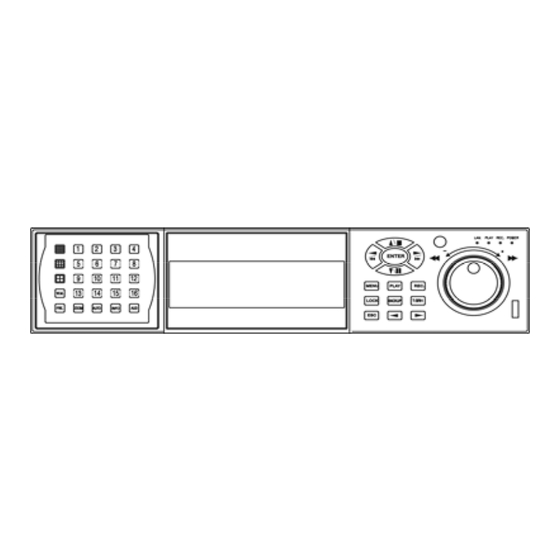
Page 5: Unite Description Of Front Panel
Unit Description of Front Panel 16 / 9 / 4 split screen 1 ~ 16 full screen Water Mark function Freezer / Zoom / Sequence / Information / Audio Menu button MENU : Play button PLAY : Record button REC : Key lock button LOCK : Data back up button... -
Page 6: Unit Description Of Rear Panel
Unit Description of Rear Panel Power cord in 12V/5A, power switcher (ON / OFF) Camera 1 ~ 16 in and 75 Ohm ON/OFF (high/low adjust) looping out Audio channel input x 1 and output x 1 VG A VGA output. PC monitor connector. Main Monitor S-Video (Y/C) monitor (Optional) -
Page 7: Installation
Installation Procedure 1) Camera Connection Connect the camera to the CAMERA INPUT LEVEL VIDEO MONITOR on the Rear Panel of the 16 CH DVR. VIDEO LENS AC24V/DC12 Rear part of CAMERA 2) Monitor Connection (Composite Connection Method) Connect the monitor to the MONITOR OUT on MONITOR the Rear Panel of the 16 CH DVR. - Page 8 NOTICE: Sensor input is RECOGNIZED as LOW when alarm signal is on a level with GND, and it is recognized as HIGH when alarm signal is FLOATING or 5V. Following is internal circuit. Internal Circuit Thus, there is a danger of damage, when the sensor input goes to a Negative level or voltage higher than 5V. 5) Network Connection DVR connects to LAN ETHERNET...
- Page 9 5) HDD connection How to connect single HDD How to connect 2 HDD I/O BOARD I/O BOARD MASTER HDD1 MASTER MAIN BOARD MAIN BOARD SLAVE HDD2 Set the drive jumpers as specified by hard disk drive manufacturer. Set the drive jumpers as specified by hard disk drive manufacturer. Make sure the HDD is MASTER.
- Page 10 Picture Full screen or split screen display Press button, to display 16 / 9 / 4 quarterly split screen. Press numeric buttons to display the desired camera image in full screen. 1.) FREEZE Mode 1. In live mode press (FREEZE) button to freeze image. 2.
- Page 11 6.) BACKUP. Image backup mode.(Image back up must be done on playback mode only.) Locate the playback point of which you want. Press BACKUP, the BACKUP CAUTION window pop-up. Press ENTER to begin data back up. Capacity of USB device is not limit. On playback mode, presses BACKUP: Lower-Right corner of the screen: ** BACKUP CAUTION **...
- Page 12 8.) AUDIO function )))) )))) xxxxxxxxx Audio playback: AUD (Audio), )))))))displays on the Upper-left of screen. At that time, audio will playback. Press it again to turn it off. Notice Audio playback only on normal( x 1 ) playback. 9. NETWORK Playing NETWORK PLAYING PASSWORD : (*****) ENTER PASSWORD TO TERMINATE...
- Page 13 Playback 1. Playback Mode 1) Press button to begin playback. (System playback the images backward) PLAY 2. T-SRH button MAIN PLAY PAGE 1) T-SRH: Playback by time search. 1.MASTER TIME LIST Press T-SRH button to active playback function. 2.SLAVE TIME LIST 3.MASTER EVENT LIST Press direction button 4.SLAVE EVENT LIST...
- Page 14 2) EVENT LIST (Alarm List): Event source- Video loss / Alarm trigger / Motion / Record EVENT LIST +10 NO Y / M / D H : M CH EVENT 10 items display on each page / Total 5000 items display for 500 pages. When event list is out of compass, the total items are less then 5000.
-
Page 15: Function Setup
Function Setup LOGIN MENU 1) Press button to enter into menu. You could do the system function setup in MENU. 2) Password enter window pop-up: CHECK PASSWORD MENU Default password (Account-Admin) : 44444 Default password (Account-User) : 11111 PASSWORD (*****) 3) Press numeric (1 ~ 10 )button or remote controller ( 1 ~ 10 )to choose password. -
Page 16: Basic Operation
Basic Operation Press MENU button to enter MAIN SETUP PAGE. MAIN SETUP PAGE 1. HDD INFORMATION 2. DATE-TIME SETUP 3. DISPLAY SETUP 4. CAMERA SETUP 5. BUZZER SETUP 6. RELAY SETUP 7. SYSTEM SETUP 8. ADVANCED SETUP MENU, ESC: EXIT, ENTER: RUN 1) Use direction button up/down button to select setup item. - Page 17 1. HDD INFORMATION MAIN SETUP PAGE POSITION SIZE USED BRAND 1. HDD INFORMATION 2. DATE-TIME SETUP MASTER 3. DISPLAY SETUP LAST TIME 4. CAMERA SETUP SLAVE 5. BUZZER SETUP LAST TIME 6. RELAY SETUP 7. SYSTEM SETUP MENU, ESC: EXIT, :PAGE 8.
- Page 18 2. DATE-TIME SETUP MAIN SETUP PAGE 1. HDD INFORMATION DATE-TIME SETUP PAGE 1. DATE 2000 / 00 / 00 2. DATE-TIME SETUP 3. DISPLAY SETUP 2. TIME 4. CAMERA SETUP 3. FORMAT 5. BUZZER SETUP 3. DISPLAY AT xx LINE(S) 6.
- Page 19 3. DISPLAY SETUP MAIN SETUP PAGE 1. HDD INFORMATION DISPLAY SETUP PAGE 2. DATE-TIME SETUP 1. DATE-TIME 2. CAMERA TITLE 3. DISPLAY SETUP 4. CAMERA SETUP 3. PB DATE-TIME 5. BUZZER SETUP 4. PB CAMERA TITLE 6. RELAY SETUP 5. PB DUMMY CAMERA 7.
- Page 20 4. CAMERA SETUP MAIN SETUP PAGE CAMERA SETUP PAGE 1. HDD INFORMATION 1. COLOR SETUP 2. DATE-TIME SETUP 2. TITLE SETUP 3. DISPLAY SETUP 3. SCREEN POSITION SETUP 4. CAMERA SETUP 4. V-LOSS DISPLAY SETUP 5. BUZZER SETUP 5. VIDEO MASK SETUP 6.
- Page 21 (2.) TITLE SETUP: Input TITLE of each camera. 9 characters can be input. TITLE SETUP PAGE CH 01 (01 CH 09 (09 ) CAMERA SETUP CH 02 (02 CH 10 (10 ) 1. COLOR SETUP CH 03 (03 CH 11 (11 ) 2.
- Page 22 (3.) SCREEN POSITION SETUP **** SCREEN POSITION**** CAMERA SETUP 1. COLOR SETUP LEFT RIGHT 2. TITLE SETUP 3. SCREEN POSITION SETUP DOWN 4. V-LOSS DISPLAY SETUP ENTER : DEFAULT 5. VIDEO MASK SETUP : QUIT Press direction buttons up/down/left/right to move screen position. 2.
- Page 23 (4.) V-LOSS DISPLAY SETUP VLOSS SETUP PAGE **V-LOSS FUNCTION: CAMERA SETUP CH 01 : ON CH 09 : ON 1. COLOR SETUP CH 02 : ON CH 10 : ON 2. TITLE SETUP CH 03 : ON CH 11 : ON 3.
- Page 24 (5.) VIDEO MASK SETUP VIDEO MASK SETUP PAGE **VIDEO MASK FUNCTION: CH 01 CH 09 CAMERA SETUP CH 02 CH 10 1. COLOR SETUP CH 03 CH 11 2. TITLE SETUP CH 04 CH 12 3. SCREEN POSITION SETUP CH 05 CH 13 4.
- Page 25 5. BUZZER SETUP MAIN SETUP PAGE BUZZER SETUP PAGE 1. HDD INFORMATION **BUZZER FUNCTION 2. DATE-TIME SETUP BUTTON BUZZER 3. DISPLAY SETUP ALARM BUZZER 4. CAMERA SETUP MOTION BUZZER V-LOSS BUZZER 5. BUZZER SETUP 6. RELAY SETUP HDD-FULL BUZZER 7. SYSTEM SETUP CRASH BUZZER...
- Page 26 6. RELAY SETUP MAIN SETUP PAGE 1. HDD INFORMATION RELAY SETUP PAGE 2. DATE-TIME SETUP **RELAY FUNCTION: ON 3. DISPLAY SETUP 1. ALARM RELAY: 4. CAMERA SETUP 2. MOTION RELAY: 5. BUZZER SETUP 3. V-LOSS RELAY: 4. HDD-FULL RELAY: 6. RELAY SETUP 7.
- Page 27 7. SYSTEM SETUP MAIN SETUP PAGE SYSTEM SETUP 1. HDD INFORMATION 1. DWELL INTERVAL 2. DATE-TIME SETUP 2. LANGUAGE 3. DISPLAY SETUP 3. VIDEO INPUT 4. CAMERA SETUP 4. RS-485 ID 5. BUZZER SETUP 5. RS-485 PROTOCOL 6. RELAY SETUP 6.
- Page 28 8. ADVANCED SETUP MAIN SETUP PAGE ADVANCED SETUP PAGE 1. HDD INFORMATION 1. ALARM SETUP 2. DATE-TIME SETUP 2. MOTION SETUP 3. DISPLAY SETUP 3. RECORD SETUP 4. CAMERA SETUP 4. PASSWORD SETUP 5. BUZZER SETUP 5. NETWORK SETUP 6. RELAY SETUP 6.
- Page 29 2. MOTION SETUP MOTION SETUP PAGE ADVANCED SETUP PAGE **MOTION FUNCTION ON 1. ALARM SETUP **MOTION DURATION 2. MOTION SETUP **CHANNEL NUMBER 3. RECORD SETUP 1. SENSITIVITY 4. PASSWORD SETUP 2. VELOCITY 5. NETWORK SETUP 3. ACTIVATION 6. HDD FORMAT 4.
- Page 30 > MOTION AREA SETUP < All area detect with factory default. Press ENTER button to change mode and then increase or reduce. For example: Clear lattices Press value change button to reduce. Add lattices Press value change button to reduce. Icon: Press to increase all area, press...
- Page 31 3. RECORD SETUP ADVANCED SETUP PAGE RECORD SETUP 1. ALARM SETUP 1. HDD FULL 2. MOTION SETUP 2. RECORD SPEED 3. RECORD MODE 3. RECORD SETUP 4. PASSWORD SETUP 4. RECORD AUDIO 5. NETWORK SETUP 5. QUALITY 6. HDD FORMAT 6.
- Page 32 RECORD SPEED: Record FPS setup -1/30(1/30), 1/15(1/15), 1/10(1/10), 1/5 (1/5), 1/3 (1/3), 1/2 (1/2), 1(1), 2(2), 3(3.13), 5(5), 10 (8.33), 15(12.5), 30(25), 60(50), 120(100). NTSC / (PAL) RECORD MODE: Record mode setup. -ALWAYS / SCHEDULE / EVENT / EVENT ON SCHEDULE / EVENT + SCHEDULE RECORD AUDIO: Audio record setup -ON / OFF.
- Page 33 >SCHEDULE SETUP< RECORD SETUP 1. HDD FULL Press direction buttons up/down to 2. RECORD SPEED SCHEDULE items. 3. RECORD MODE 4. RECORD AUDIO Press values change button to change values. 5. QUALITY 6. SCHEDULE SETUP Factory default is everyday all schedules time on 7.
- Page 34 30MIN SCHEDULE SETUP CURSOR STEP 00:00 01:00 02:00 03:00 04:00 05:00 06:00 07:00 08:00 09:00 10:00 11:00 12:00 13:00 14:00 15:00 16:00 17:00 18:00 19:00 20:00 21:00 22:00 23:00 00:30 01:30 02:30 03:30 04:30 05:30 06:30 07:30 08:30 09:30 10:30 11:30 12:30 13:30 14:30 15:30 16:30 17:30 18:30 19:30 20:30 21:30 22:30 23:30 00:00 01:00 02:00 03:00 04:00 05:00 06:00 07:00 08:00 09:00 10:00 11:00 12:00 13:00 14:00 15:00 16:00 17:00 18:00 19:00 20:00 21:00 22:00 23:00 00:30 01:30 02:30 03:30 04:30 05:30 06:30 07:30 08:30 09:30 10:30 11:30 12:30 13:30 14:30 15:30 16:30 17:30 18:30 19:30 20:30 21:30 22:30 23:30 00:00 01:00 02:00 03:00 04:00 05:00 06:00 07:00 08:00 09:00 10:00 11:00 12:00 13:00 14:00 15:00 16:00 17:00 18:00 19:00 20:00 21:00 22:00 23:00...
- Page 35 7) RECORD CHANNEL SETUP PAGE RECORD CHANNEL SETUP PAGE RECORD SETUP CH 01 CH 09 1. HDD FULL CH 02 CH 10 2. RECORD SPEED CH 03 CH 11 3. RECORD MODE CH 04 CH 12 4. RECORD AUDIO CH 05 CH 13 5.
- Page 36 4. PASSWORD SETUP ADVANCED SETUP PAGE 1. ALARM SETUP 2. MOTION SETUP PASSWORD SETUP PAGE 3. RECORD SETUP 1. LEVEL:( 2. ADMIN:( 4. PASSWORD SETUP 5. NETWORK SETUP USER :( 6. HDD FORMAT 7. FACTORY DEFAULT 8. SOFTWARE UPDATE Press direction buttons up/down/left/right to LEVEL (Log In level ID type setup) Choose items position.
- Page 37 5. NETWORK SETUP ADVANCED SETUP PAGE TCP-IP SETUP PAGE 1. ALARM SETUP 1. SPEED: 2. MOTION SETUP 2. IP TYPE : OFF 3. RECORD SETUP 3. IP ADDR: xxx.xxx.xxx.xxx 4. PASSWORD SETUP 4. GATEWAY: xxx.xxx.xxx.xxx 5. NETMASK: xxx.xxx.xxx.xxx 5. NETWORK SETUP 6.
- Page 38 6. HDD FORMAT ADVANCED SETUP PAGE Press direction buttons up/down to 1. ALARM SETUP HDD FORMAT items position. 2. MOTION SETUP Press ENTER to format all HDD. 3. RECORD SETUP 4. PASSWORD SETUP Caution: User can format HDD only when 5.
- Page 39 7. FACTORY DEFAULT ADVANCED SETUP PAGE 1. ALARM SETUP Press direction buttons up/down to 2. MOTION SETUP FACTORY DEFAULT items position. 3. RECORD SETUP Press ENTER to restore. 4. PASSWORD SETUP 5. NETWORK SETUP 6. HDD FORMAT 7. FACTORY DEFAULT 8.
-
Page 40: Usb Data Read And Networking
USB Data Read and Networking character display. 1. Windows 2000 / XP, select small 2. Resolution 1024 x 768. 3. RAM up to 128 MB, system up to PIII-800. 4. Double click SETUP.EXE of CD, and then start to install. 5. - Page 41 7. Advice resolution 1024 x 768. According computer equipment, please choose suitable resolution 8. Select Start Menu Folder, and then click Next.
- Page 42 9. Click create a desktop icon or not, and then click Next. 10. Click INSTALL to start install.
- Page 43 11. Click Launch NetViewer 16CH and click Finish to done.
- Page 44 12. Click Setting. Name: Name the IP address position.(Each name and IP saves every different input) IP Addr: Input DVR IP address. AVI codec: Different computer equipment; different AVI format. Microsoft Windows Media video 9 is better. Or Cinepak Codec by Radius / Microsoft Video 1. Video: Fullsize, Halfsize: screen size choose.
- Page 45 13. Click Login, depends on limits of authority. (ID / password is same as DVR) Factory ID is user login. Input admin if you are an administer. Must input on little character. Factory: Password, admin : 44444, user : 11111. Password displays when log in, user just needs to input ID. User log in, no PlayBack function authority.
- Page 46 14. Click Connect, after about 2 ~ 3 seconds to start connect LAN or WAN. Click Disconnect to stop. If the NETWORK is connecting success, the blue light would keep glisten Else, blue is always on light or not display, the connecting is failed. Click live / PlayBack / BackPlay mode.
- Page 47 PLAY: Click RUN around 2 ~ 30 seconds to start play first record. If over 30 seconds, cannot find any file or network disconnect, Time out message popup. Please try again play or connect again. Click STOP to end playback. TIME LIST: Click RUN, time lists popup.
- Page 48 -Master HDD Event Lists: -Slave HDD Event Lists: Click RUN, time lists popup. On the item, double click date and time to start play, around 2 ~ 30 to start play first record. If over 30 seconds, cannot find any file or network disconnect, Time out message popup. Please try again play or connect again.
- Page 49 15. BackupPlay: - Click Open to choose file path.
- Page 50 Click Play to start backup data play. Click Stop to end. Click Pause to temporary stop playback. Click Resume to restart. Choose camera, click mouse right button. Camera 1 ~ 16 switches or reset all. Click Save “CamNo xx image . / save image all to save current image.
- Page 51 16. AVI transfer: Click BackupPlay AVI : On live or playback mode, save files to .DVR file. And then OPEN file, press play to start playback. Press AVI button to start record AVI file. Press again to stop. Only 2 cameras selectable. A warning message appears if user selects over 3 cameras,...
-
Page 52: Record Time Table: 80Gb Hd
Record Time Table: 80GB HD Record Quality: Low. KB Range: Lowest: 13, Highest: 20. Average: 17. REC FPS REC Hour REC FPS REC Hour 1370 2741 REC FPS 1/10 1/15 1/30 REC Hour 4112 6853 13706 20565 41140 Record Quality: Normal. KB Range: Lowest: 14, Highest: 25. Average: 20. REC FPS REC Hour REC FPS... -
Page 53: Vga Description (Optional)
VGA Description (Optional) Accessories: 1. 20 PIN Male to Female D-SUB pin cable X 1 2. VGA PCB bracket X1 3. Screws X4 1. VGA board introduction. VGA connector Socket 2. Resolution switcher table Pin 4 Resolution Pin 1 Pin 2 Pin 3 640X480 60HZ 800X600 60HZ... -
Page 54: Additional
Additional Hard Disk x 2 can be installed on DVR base. Both are 2-iron slices immobile type. 2 Iron slices are in the accessories box, please tell supplier if slices are not exist 2-iron slices immobile type: Slices immobile type: 4 screws hole on each slice. 2 for DVR base fixed. Another 2 for hard disk fixed. Hard disk install.: Locking hard disk screws, then locking DVR base screws to fixed on. - Page 55 P / T / Z Dome mode. (Optional) 6. ADVNACED SETUP PAGE P.T.Z SETUP ADVANCED SETUP PAGE PTZ SETUP PAGE 1. ALARM SETUP CHANNEL NUMBER 2. MOTION SETUP 1. ID 3. RECORD SETUP 2. PROTOCOL 4. PASSWORD SETUP 3. BAUDRATE 5.
- Page 56 Front Panel Button Comparison: W.M.: To P / T / Z mode PLAY / REC = IRIS off / IRIS open = FOCUS near / FOCUS far BACKUP / T-SRH = ZOOM IN / ZOOM OUT MENU = P / T / Z Dome Menu FRE.
- Page 57 Network Setup Sets LAN or WAN IP address of DVR. b.) Open IE browser, and then into your IP on the IE address bar. c.) If LAN or WAN connects ok, the 16 Channel Digital Video Recorder web page displays like under:...
Need help?
Do you have a question about the 16 Channel Digital Video Recorder and is the answer not in the manual?
Questions and answers
How do I reset my password
The provided context does not include instructions for resetting the password on a Hi Sharp 16 Channel Digital Video Recorder. However, it does mention the default passwords:
- Admin Default Password: 44444
- User Default Password: 11111
If you need to reset the password, you may need to check the DVR's manual or contact the manufacturer for specific reset instructions.
This answer is automatically generated