
Related Manuals for Hi Sharp HS-AHR600


Summary of Contents for Hi Sharp HS-AHR600
- Page 1 Thank you for purchasing our product. Please read this user’s manual before using the product. Change without notice H.264 4/ 8/ 16 CH DVR User’s Manual...
- Page 2 CAUTION Please read this user manual carefully to ensure that you can use the device correctly and safely We do not warrant all the content is correct. The contents of this manual are subject to change without notice ...
- Page 3 Main Features Real-time surveillance High resolution VGA output (Default), HDMI output available 2 way audio 3G Mobile surveillance(Iphone/ iPad/ Android) Compression with latest H.264 video compression, better video quality and lower compression rate. Storage 1 SATA HDD for 4/8/16 channel DVR(FAT32 file system) ...
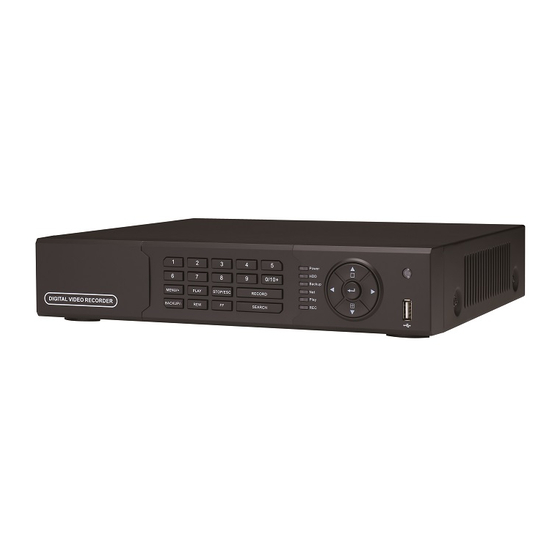
- Page 4 Front Panel Instructions Notice: The pictures are only for reference; please make the object as the standard. Label Name Function REC / FOCUS Manual record / focus adjustment(PTZ) PLAY / IRIS Enter Playback/ iris adjustment (PTZ) REW / SPEED Fast rewind on playback mode /speed adjustment (PTZ) FF / P.T.Z.
- Page 5 1.3 Back Panel Definition 1.3.1 Fig 2-1 Rear Panel for 4-ch Rear Panel for 4-ch Name Description Audio in 4 CH Audio input RS485 Connect to speed dome or keyboard ALARM OUT 1-ch relay output. Connect to external alarm ALARM IN Connect to external sensor 1-4 Video in Video input channels from 1-4...
- Page 6 Rear Panel for 8-ch Name Description Audio in 4 CH Audio input RS485 Connect to speed dome or keyboard ALARM OUT 1-ch relay output. Connect to external alarm ALARM IN Connect to external sensor 1-8 Video in Video input channels from 1-8 Audio out Audio output, connect to the sound box Video out...
- Page 7 Remote Controller (Optional) It uses two AAA size batteries and works after loading batteries as following: Step1: Open the battery cover of the Remote Controller Step2: Place batteries. Please take care the poles (+ and -) Step3: Replace the battery cover Notice: Frequently defect checking as following 1.
- Page 8 1.5 Control with Mouse 1.5.1 Connect Mouse It supports USB mouse through the port on the rear panel, please refer to Fig 2.11 Remote Controller. Notice: If mouse is not detected or doesn't work, check below steps: 1. Make sure the mouse is connected to the USB mouse port not the USB port 2.
- Page 9 Basic Function Instruction Power On/Off Before you power on the unit, please make sure all the connection is good. 2.1.1 Power on Step1: connect with the source power; switch on the power button near the power port in the rear panel Step2: the device will start to boot, and the power indicator will become blue Step3: before start, a WIZARD dialogue box will pop-out (refer to below picture) and show some information about time zone and time setup, IP information, record quick setup and HDD information page.
- Page 10 Live preview Fig 3-2 live preview interface The explanation of symbol in the live preview interface: symbol meaning symbol meaning Alarm in trigger Green Manual record record Yellow Motion detection record Blue Schedule record 2.3.1 Live playback Click Play button to playback the recorded video. Refer to Figure3-3. User can do concrete operation by click the buttons on screen.
- Page 11 Fig 3-3 live playback Item Function Description Camera name Enable or disable camera name display Playback process bar Last/next segment of record and time process Enable to select a specific part of the video and back it up on usb drive Play/ Pause / Stop / frame forward / fast forward Playback basic function / fast rewind...
- Page 12 Main menu setup guide Click right mouse or press ESC button on the front panel, the control bar will display on the screen, refer to Fig 4-1: Full channel switch, camera 1 ~ 4 or camera 1 ~ 8, camera 1 ~ 16 ①...
- Page 13 Basic configuration Basic configuration includes three sub menus: system、date& time and DST. 3.1.1 System Step1: enter into system configurationbasic configurationsystem; refer to Fig 4-3: Fig 4-3 basic configuration-basic Step2: in this interface user can setup the device name, device ID, video format, max network users, VGA resolution and language.
- Page 14 3.1.3 DST Step1: enter into system configurationbasic configurationDST; refer to Fig 4-5: Fig 4-5 basic configuration-DST Step2: in this interface, enable daylight saving time, time offset, mode, start & end month/week/date, etc. Step3: click “default” button to resort default setting; click “apply” button to save the setting; click “exit” button to exit current interface.
- Page 15 to exit current interface. 3.2.2 Main monitor Step1: enter into system configurationlive configurationhost monitor; refer to Fig 4-8: Fig 4-8 live configuration-host monitor Step2: select split mode: 1×1、2×2、2×3、3×3、4×4 and channel Step3: dwell time: the time interval for a certain dwell picture display switching to next dwell picture display Step4: selected the split mode, then setup current picture group.
- Page 16 3.2.4 Mask User can setup private mask area on the live image picture, max threes areas. Fig 4-10 live configuration-mask Setup mask area: click Setting button, enter into live image to press left mouse and drag mouse to set mask area, refer to below picture.
- Page 17 Record configuration Record configuration includes five sub menus: enable, record bit rate, time, recycle record and stamp. 3.3.1 Enable Step1: enter into system configurationrecord configurationenable; refer to Fig 4-11: Fig 4-11 record configuration-enable Step2: tick off record, audio and record time Step3: user can setup all channels with same parameters, tick off “all”, then to do relevant setup.
- Page 18 Note: if the rate value set is over high the maximum resources of the device, the value will be adjusted automatically. Definitions and descriptions of Record stream: Resolution: CIF, HD1 or D1 4 CH 4CIF@30(25) 4HD1@30(25) 4D1@30(25) 8D1@18(15) or 8 CH 8CIF@30(25) 8HD1@30(25) 4 D1@30(25)+4CIF30(25)
- Page 19 3.3.4 Stamp Stamp:User can overlap the channel name and time stamp on video. Step1: enter into system configuration record configuration stamp; refer to Fig 4-13: Fig 4-13 record configuration-stamp Step2: tick off camera name, time stamp; click Set button, user can use cursor to drag the camera name and time stamp in random positions, refer to below Figures: Before drag after drag...
- Page 20 Step1: enter into system configurationschedule configurationschedule; refer to Fig 4-14: Fig 4-14 schedule configuration-schedule Step2: select channel, double-click and a dialog box will pop-up as Fig 4-15, user can edit week schedule: Fig 4-15 schedule-week schedule ① Click “add” button to add a certain day schedule; click “delete” button to delete the selected schedule; Copy: user can copy the specify schedule to other dates.
- Page 21 Note: the default schedule of motion detection is full-selected, that is, the color of schedule setting interface is blue. 3.4.3 Sensor Step1: enter into system configurationschedule configurationalarm; refer to Fig 4-17: Step2: the setup steps of alarm are familiar with schedule; user can refer to 4.4.1 Schedule for details. Note: the default schedule of sensor is full-selected, that is, the color of schedule setting interface is blue.
- Page 22 Step1: enter into system configurationalarm configurationsensoralarm handling; refer to Fig 4-19: Fig 4-19 alarm configuration-sensor-alarm handling Step2: select hold time, click Trigger button, and a dialog box will pop-up as Fig 4-20: Fig 4-20 alarm handling-trigger Step3: tick off Buzzer, there will be triggered buzzer alarm out; Full screen alarm: when triggered alarm, there will pop up full screen alarm;...
- Page 23 details. Note: the default schedule of sensor is full-selected, that is, the color of schedule setting interface is blue. 3.5.2 Motion Motion includes two sub menus: motion and schedule. ① Motion Step1: enter into system configurationalarm configurationmotion; refer to Fig 4-22: Fig 4-22 alarm configuration-motion Step2: enable motion alarm, set alarm hold time which means time interval between two adjacent detective motions.
- Page 24 Step1: enter into system configurationalarm configurationschedule; refer to Fig 4-24: Fig3-24 alarm configuration-schedule Step2: the setup steps of alarm schedule are familiar with schedule; user can refer to 4.4.1 Schedule for details. 3.5.3 Video loss Step1: enter into system configurationalarm configurationvideo loss; refer to Fig 4-25: Fig 4-25 alarm configuration-video loss Step2: the setup steps of video loss trigger are familiar with alarm handling;...
- Page 25 Step3: click “default” button to resort default setting; click “apply” button to save the setting; click “exit” button to exit current interface. 3.5.5 Alarm out Alarm out includes three sub menus: alarm out, schedule and buzzer ① Alarm out Step1: enter into system configurationalarm out; refer to Fig 4-27: Fig 4-27 system configuration-alarm out Step2: in this interface, set relay alarm out name, select hold time which means the interval time between the two adjacent alarms.
- Page 26 typing IP address in IE address blank .i.e. set HTTP port to 82, IP address: http://192.168.0.25, user needs to input that address: http://192.168.0.25:82 into IE browser. Server port: communication port There are 3 different types to connect internet, please select an appropriate type to fit your network environment.
- Page 27 Step3: user can setup all channels with same parameters, tick off “all”, then to do relevant setup. Step4: click “default” button to resort default setting; click “apply” button to save the setting; click “exit” button to exit current interface. Definitions and descriptions of network stream: Parameter Meaning Range from: 1-12(PAL) /1-15(NTSC)
- Page 28 Fig 4-32 network configuration-other settings STEP2: click “default” button to resort default setting; click “apply” button to save the setting; click “exit” button to exit current interface. Note: The domain name server that selected by user is a banding domain name of DVR. User should logon the website which provided by the server supplier to register a user name and password firstly, and then apply a domain name on line for the server.
- Page 29 computer; the, the user can log in DVR on the binding computer after set the specific binding MAC address. ② Authority: a) Admin: Admin have full control of DVR. DVR could have only one admin account. b) Advance: Besides ”firmware upgrade”, ”reset factory default”, ”shut down” and ”change other user’s password”, advance account could control DVR like an admin account.
- Page 30 Step1: enter into system configuration P.T.Z configurationadvance; refer to Fig 4-37: Fig 4-37 P.T.Z configuration-advance Step2: in the Advance interface, click preset “Setting” button, a dialog box will pop-up as Fig 4-38: Fig 4-38 advance-preset setting a. in the preset set interface, click Setting button, a dialog will pop-up as Fig 3-39: Fig 3-39 preset set-setting b.
- Page 31 Fig 4-40 cruise set a. click Add button to add cruise line in the list box (max 8 cruise line can be added); select a cruise line, click Setup button, a dialog box will pop-up as Fig 4-41: Fig 4-41 cruise set-modify cruise line b.
- Page 32 Record search & playback and backup Search configuration includes three submenus: time search, event search and file manager. Time search Step1: enter into Search configurationtime search; refer to Fig 5-1: Fig 5-1 Search configuration-time search Step2: select channel, screen display mode, the highlight date in the calendar means have record data Step3: select a date, press Search button, click the time grid to set the play start time or input play record time manually.
- Page 33 File manager Step1: enter into Search configurationfile manager; refer to Fig 5-3: Fig 5-3 Search configuration-file manager Step2: click Search button, the searched files will be displayed in the file list box, user can select date, channels accordingly. ① Lock: checked a file, click Lock button to lock this file, after that, that file will not be deleted or covered. ②...
- Page 34 Fig 5-5 backup information Step4: in the backup information interface, user can check the relevant information of backup files, storage type, save file type, etc. click Apply button to starting backup. Note: when the monitor resolution is VGA800*600, the file manager interface will appear a hide button, click this button, the whole interface can be expanded.
- Page 35 Manage DVR Check system information Check system information includes five submenus: system, event, log, network and online user. 5.1.1 System information In this interface, user can check the hardware version, MCU version, kernel version, device ID, etc. refer to Fig 6-1: Fig 6-1 system information 5.1.2 Event information In this interface, user can check record events according to set date;...
- Page 36 Fig 6-4 network information 5.1.5 Online information In this interface, user can check the details of the current connection of online users; refer to Fig 6-5: Fig 6-5 online information 5.1.6 Manual alarm User can check the relevant parameters of manual alarm to active emergency warning 5.1.6 Disk manager Step1: enter into disk manager interface;...
- Page 37 disk-free space, and total space show OM at the bottom of screen. Step2: click Refresh button to refresh the disk information of the list box; set the property of the disk then click Apply button to save the setting Step3: checked a hard disk, click Format button to star format. Note: all recorded files in the hard disk will be lost after formatted.
- Page 38 Remote Surveillance Accessing DVR If making remote view, the DVR must connect with LAN or internet. Then enable network server in the unit. Please refer to 4.6 Network Configuration. This unit supports IE browser, without any client software installed. It supports Win 7, XP and Vista. 6.1.1 On LAN Step1: Input IP address, Subnet, Gateway.
- Page 39 Step1: Input IP address, Subnet, Gateway gotten from your ISP. If using ADSL, please input user name and password, and click OK. The DVR will connect the server and show “connection succeeds”. Step2: The following steps are the same as STEP4-7 of the connection way above. The remote live preview interface as below: Fig 7-2 Remote live preview interface Symbol and function Definitions:...
- Page 40 Buttons Description Drag the scroll bar to adjust the brightness of channel Drag the scroll bar to adjust the contrast of channel Drag the scroll bar to adjust the saturation of channel Drag the scroll bar to adjust the hue of channel Click this button to recover the default value of brightness, contrast, saturation and hue.
- Page 41 Remote playback & backup 6.3.1 Remote playback Click button to enter into record playback interface, refer to Fig 7-5: Select the record date and channels; double-click the file name in the record file list box, user can play that file and preview the picture.
- Page 42 Fig 7-7 Time search playback By Event Search: Step1: Enter into Searchevent search; refer to Fig 7-8: Fig 7-8 event search interface Step2: click the highlight date and select record channels and then tick off the event type: motion and sensor, click “search”...
- Page 43 Fig 7-9 file management interface Lock: select certain file item in the file list box, click “Lock” button to lock this file that ca not be deleted or overlaid Unlock: select a locked file, click “unlock” button to unlock this file Delete: select an unlock file, click “delete”...
- Page 44 Fig 7-11 remote menu setup The sub menu lists and the options in every item are similar with those on the DVR. Please refer to Chapter 3 Main Menu Setup Guide for more details. Click “Apply” button to save above settings; click “default” button will recover the original settings. Remote Management Remote Information Search The system will automatically record the working condition and operation process during the period of work.
- Page 45 Mobile Surveillance This DVR supports mobile surveillance on Iphone and android OS device, this section describes the installation of the program via the Smartphone 7.1 Installation procedure on Iphone device At present, the software only supports version of Iphone iOS 3.1.2 and above, if phone firmware lower than this version please upgrade it.
- Page 46 Step 5: Just be patient to download and install. After installed, “SuperLivePro”, icon will display. Click this icon, a function interface will appear Step 6: Key in server’s IP address (or domain name), user’s ID and password. Click Login to process. Step 7: The default quad view window will be displayed.
- Page 47 7.2 Installation procedure on Android OS Smartphone On your Smartphone click on the Google play store icon Then press on search icon on right Type SUPERLIVEPRO with your virtual keyboard and press enter The search result will show the Click SUPERLIVEPRO, brief available applications...
- Page 48 Click on ACCEPT & DOWNLOAD The program is being downloaded on your smartphone, please wait The program is being installed on your The installation is finished, click Open to smartphone launch the program,...
- Page 49 Key your DVR IP, the username and You are connected to the DVR, you can password, if you want the program to keep see all the functions of the program in memory select REMEMBER SERVER, then click on LOGIN Main interface description Item Description Playback...
- Page 50 Live picture interface Icon Description One screen Four screen Channel configure PTZ control Capture Record Talk Channel audio Hide SuperLivePro...
-
Page 51: Appendix A Faq
Appendix A Q1. Why the DVR cannot start after connected to the power? a. The adapter has been damaged. Please change an adapter b. The power of the adapter is not enough. Please remove the HDD to check c. Hardware problem Q2. - Page 52 Fig7-1 Fig7-2 Q8: How to deal with when DVR starts, it displays “please wait…”all the time First possible reason: hard-disk cable and data cable are not well connected. Solution: Please check the connection of hard-disk cable and data cable and make sure they are well connected;...
- Page 53 Q12: What are the minimum configurations of PC for clients connecting? PC Module Parameters Intel Celeron 2.4G Motherboard Intel 845 512M NVIDIA GeForce MX440/FX5200 ATIRADEON 7500/X300 Windows 2000(SP4 above) /Windows XP(SP2 above) /VISTA/SEVEN DirectX Q13: What are the PC configurations for 8-ch real time product with fully open channel mainstream? PC Module Parameters Intel Core(TM)2 Duo CPU E4600...
- Page 54 Appendix B Calculate Recording Capacity Users can calculate the size of hard disk according to the saving time and DVR recording settings. The DVR uses fixed video bit rate. The below are the details at different settings. Video Frame Rate Bit Rate Used Resolution...
- Page 55 Appendix C Compatible Devices Compatible Devices Compatible USB drive after test. Brand Capacity A-DATA 512MB, 1G, 2GB Transcend Kingston Toshiba SanDisk 2. Compatible external USB CD/DVD writers after test Brand Model GH24NS90...
- Page 56 3. Compatible HDD Brand Model number Capacity 1600AAJS FW:00L7A0 160GB 2500AVVS FW:73M8B0 250GB 3200AVVS 320GB 5000AVDS FW:63U7B0 500GB 5000AVJS FW:63YJA0 500GB 5000AVVS FW:63M8B0 500GB 5000AAKS FW:00V1A0 500GB 5000BUDT (2.5") FW:63G8FY0 500GB WESTERN DIGITAL 5000AUDX FW:63WNHY0 500GB 10EURS FW:630AB1 10EVDS FW:63U8B0 15EARS FW:00Z5B1 1.5TB 15EURS FW:63S48Y0...
- Page 57 APPENDIX D DDNS setup procedure (Take www.geekciti.com as an example) Visit www.geekciti.com and register new account by filling each line then press submit, you need to have a valid email which will be use as username Create a domain name as your convenience and choose the extension among the list available, then click on REQUEST DOMAIN...
- Page 58 If the domain exists already you will have to choose another domain name, if not you will see the below screen Fill all setting on DVR then click “Test” to verify. Then click “Apply” to Finish DVR network setting. (Menu-> Network ->...
- Page 59 You can test with a computer with internet explorer browser by key in the new domain name You will see the DVR main page, after key in the username and password as well the display language, you should be able see camera live display...
Need help?
Do you have a question about the HS-AHR600 and is the answer not in the manual?
Questions and answers