
Related Manuals for Grizzly G9036


Summary of Contents for Grizzly G9036
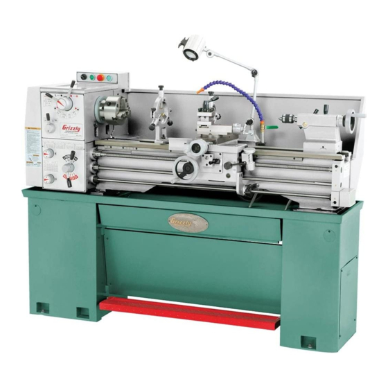
- Page 1 MODEL G9036 13" x 40" GEAR-HEAD LATHE OWNER'S MANUAL WARNING: NO PORTION OF THIS MANUAL MAY BE REPRODUCED IN ANY SHAPE OR FORM WITHOUT THE WRITTEN APPROVAL OF GRIZZLY INDUSTRIAL, INC.
-
Page 3: Table Of Contents
INTRODUCTION ... 2 SECTION 1: SAFETY ... 7 SECTION 2: CIRCUIT REQUIREMENTS ... 11 SECTION 3: SETUP ... 12 SECTION 4: OPERATION ... 19 SECTION 5: ACCESSORIES ... 40 Table of Contents SECTION 6: MAINTENANCE ... 42 SECTION 7: SERVICE ... 47 SECTION 8: WIRING ... -
Page 4: Introduction
INTRODUCTION Functional Overview Foreword www.grizzly.com Contact Info... - Page 5 Identification...
-
Page 6: Machine Data Sheet
Machine Data Sheet Customer Service #: (570) 546-9663 · To Order Call: (800) 523-4777 · Fax #: (800) 438-5901 MODEL G9036 13" X 40" GEAR-HEAD FLOOR LATHE Weight... 1320 lbs. Length/Width/Height... 71-1/2 x 30 x 53-1/2 in. Foot Print (Length/Width)... 69-1/2 x 15-3/4 in. - Page 7 Spindle Bore...1-7/16 in. Spindle Taper...MT#5 No Of Spindle Speeds...8 Range Of Spindle Speeds...70, 115, 190, 300, 460, 755, 1255, 2000 RPM Spindle Type... D1-4 Camlock Spindle Bearings... Tapered Roller Tailstock Travel... 3-3/8 in. Tailstock Taper... MT#3 Tailstock Barrel Diameter...1-1/4 in. No Of Inch Threads...32 Range Of Inch Threads...3-1/2 - 80 TPI Range Of Longitudinal Feeds...
- Page 8 Built-in Stand Carriage Mounted On/Off Control Lever Coolant System Foot Brake Front Removable Chip Tray Full Length Splash Guard Halogen Light Jog Button and Emergency Stop Removable Chip Pan Threading Dial 12" Face Plate 4 Way Turret Tool Post 6" 3-Jaw Chuck with Reversible Top Jaws 8"...
-
Page 11: Additional Safety Instructions For Lathes
Additional Safety Instructions for Lathes UNDERSTANDING THE MACHINE: CLEANING MACHINE: USING CORRECT TOOLING: ELIMINATING A PROJECTILE HAZARD: SECURING A WORKPIECE: AVOIDING OVERLOADS: MAINTAINING A SAFE WORKPLACE: Like all machinery there is potential danger when operating this machine. Accidents are frequently caused by lack of familiarity or failure to pay attention. -
Page 12: Glossary Of Terms
Glossary of Terms Arbor: Backlash: Carriage: Cross Slide: Compound Rest: Cutting Speed: Dial Indicator: Facing: Feed: Gib: VERY Headstock: Lathe Center: Leadscrew: Saddle: Spindle: Tailstock: Tool Post: Turret: Ways:... -
Page 13: Section 2: Circuit Requirements
SECTION 2: CIRCUIT REQUIREMENTS 220V Operation Serious personal injury could occur if you connect the machine to power before com- pleting the setup process. DO NOT connect the machine to the power until instructed later in this manual. Electrocution or fire could result if machine is not grounded and installed in compliance with electrical... -
Page 14: Section 3: Setup
SECTION 3: SETUP Setup Safety This machine presents serious injury hazards to untrained users. Read through this entire manu- al to become familiar with the controls and opera- tions before starting the machine! Wear safety glasses dur- ing the entire set up pro- cess! This machine and its com- ponents are very heavy. - Page 15 Inventory Mounted Inventory Components Loose Inventory Components Toolbox Inventory Components NOTICE Some hardware/fasteners on the inventory list may arrive pre-installed on the machine. Check these locations before assuming that any items from the inventory list are miss- ing. Figure 2. Figure 3.
-
Page 16: Figure
Clean Up Gasoline and petroleum products have low flash points and can explode or cause fire if used to clean machinery. NOT use these products to clean the machinery. Many cleaning solvents toxic Minimize your risk by only using these products in a well ventilated area. -
Page 17: Figure
Inspect all lifting equipment to make sure it is in perfect working order and is rated for the load before attempting to lift and move this lathe. Ignoring this warning may lead to serious personal injury or death. Figure 8... -
Page 18: Figure
Mounting Lathe Machine Mounts Figure 9. Concrete Floor Mounting Options Figure 11 Figure 10. Figure 11. Check Gearbox Oil Figure 10 Troubleshooting To begin the test run: Page 42 Faceplate Lubrication Page 44 GEARBOXES MUST BE FILLED WITH OIL! NO OIL SHIPPED WITH... -
Page 19: Figure
Otherwise the lathe may feed the apron into the chuck or tailstock and cause severe lathe damage. Before starting the saw, make sure you... -
Page 20: Recommended Adjustments
14. If you do not have cutting fluid at this time, skip this step. Page 46 Spindle Break-In NOTICE Successfully complete all of the spindle break-in steps to avoid rapid deterioration of the spindle bearings and other related parts. To correctly break-in the spindle bearings: Maintenance Spindle Speed Basic Controls... -
Page 21: Figure
OMMEND that you read books, trade maga- zines, or get formal training before begin- ning any projects. Regardless of the con- tent in this section, Grizzly Industrial will not be held liable for accidents caused by lack of training. NOTICE Complete the Test Run &... - Page 22 Spindle Speed Levers Figure 14 Never move this lever while the spindle is moving. Feed Direction Lever Figure 14 Never move this lever while the spindle is moving. Page 35 Feed Speed Controls Figure 14 Figure 15. Brake Figure 15 Figure 16.
-
Page 23: Figure
Figure 17. Spindle Lever Figure 17 Feed Change Lever Figure 17 Half Nut Lever Figure 17 Figure 18. Tailstock Handwheel Quill Lock Lever Figure 18 Tailstock Lock Lever Figure 18 Figure 18... - Page 24 Chuck & Faceplate Mounting Figure 19. PINCH HAZARD! Protect your hands and the precision ground bedways with plywood or a chuck cradle when removing the lathe chuck! The heavy weight of a falling chuck can cause serious injury. Removal Figure 19 Figure 20.
-
Page 25: Figure
Figure 22. Large chucks are very heavy. Always get assistance when removing or installing large chucks to prevent personal injury or damage to the chuck or lathe. Installation Figure Figure 23. Figure 20 Figure 23... - Page 26 Figure 24 Figure 24. Three-Jaw Chuck Step 4 Step 4 Figure 25. Reversing Jaws Figure 26. Figure 25 Figure 26...
-
Page 27: Mounting Workpiece
Figure 25 Securely clamp your workpiece and remove the chuck key! Thrown objects from a lathe can cause seri- ous injury or death to the operator and to bystanders many feet away. Four-Jaw Chuck Page 22 Large chucks are very heavy. Always get... -
Page 28: Figure
To mount a workpiece on the faceplate: Centers Page 27 Securely clamp workpiece and remove the chuck key! Thrown objects from a lathe can cause seri- ous injury or death to the operator and to bystanders many feet away. Page 21 your... - Page 29 Figure 31 Make sure your clamping application will not fail! Figure 31. Use a minimum of three independent clamp- ing devices when using faceplate. Failure to provide adequate clamping will cause workpiece to eject during operation. Centers NOTICE Failure to keep a dead center tip well lubricat- ed will damage dead center and workpiece.
-
Page 30: Mounting Center In Spindle
Mounting Center in Spindle Note: When using the dead center in the spindle, use a lathe dog so that your part will rotate with the spindle and not spin on the dead center tip. -
Page 31: Step
Offsetting Tailstock Aligning Tailstock To set up the tailstock to cut a shallow taper: Figure 35 Figure 35. Figure 36. Aligning Tailstock To align the tailstock: Note: Keep in mind that the point will have to be refinished whenever it is removed and returned to the chuck. - Page 32 Step 1 Figure 38 Figure 38. Figure 39 Figure 39. Figure 39 Figure 40 Figure 40. NOTICE DO NOT forget to lock the tailstock to the ways after each adjustment. Figure 41. Figure...
-
Page 33: Drilling With Tailstock
Running the coolant pump without ade- quate coolant in the coolant reservoir may permanently damage the coolant system on your lathe. This action is considered abuse and is not covered by the warranty. Maintenance To use the coolant system on your lathe: Figure Page 46... -
Page 34: Steady Rest
Steady Rest To install/use the steady rest: Figure 45. Figure 46 Figure 46. Figure 45 Figure 47. Follow Rest Figure 47... -
Page 35: Tool Post
Tool Post To load the tool post: Figure 48 Figure 48. Steps 1–3 Spindle Speed To calculate the correct spindle speed: Figure 49 Recommended Cutting Speeds Rough Cuts Note: These values are based on HSS cutting tools. For carbide cutting tools, double the aver- age speed. - Page 36 Cutting Speed (SFM) x 4 Spindle Speed = Diameter of Cut Example 1 Step 1: Step 2: Result: Example 2: Step 1: Step 2: Step 3: Result: Note: In most cases the calculated spindle speed will be between the available speeds. Use your best judgement when choosing either a higher or lower spindle speed.
-
Page 37: Power Feed
Power Feed NOTICE Feed rate is based on spindle RPM. High feed rates combined with high spindle speeds result in a rapidly moving carriage or cross slide. Pay close attention to the feed rate you have chosen and keep your hand poised over the feed switch. -
Page 38: Feed Rates
Figure 54. To set the feed rate: NOTICE NEVER move levers while the lathe is run- ning, and NEVER force any lever when shift- ing. If the lever will not engage, rotate the chuck by hand while keeping light pressure on the lever. -
Page 39: Thread Settings & Change Gears
Thread Settings & Change Gears Always disconnect machine from power before changing gears. Accidentally starting machine during gear changes can cause serious personal injury. To set up for 1.75 pitch metric threads: Figure 57. Side View Figure 58. Figure 57 Figure 59. -
Page 40: Threading Controls
Threading Controls Feed Direction Lever Neutral Figure 60. Feed Change Lever Figure 61. Half Nut Lever Figure 62. DO NOT engage the half nut when the spin- dle is operating over 200 RPM. Disregarding this warning may cause damage to the leadscrew and bearings. - Page 41 Figure 65 For Example: Figure 64 Indicator Scale Figure 65. Figure 64.
-
Page 42: Section 5: Accessories
SECTION 5: ACCESSORIES H6879—Lathe Operation & Maintenance Book Figure 66. Quick Change Tool Holders G5701—Boring Bar Holder ⁄ " G5704—Parting Tool Holder ⁄ G5705—Knurling Tool Holder G5703—Morse Taper Holder MT#3 G5700—Turning/Boring Holder G5699—Turning Holders ⁄ "~ ⁄ Figure 67. H6095—Digital Readout (DRO) Figure 68. - Page 43 H5786—MT#3 Long Nose Precision Center Figure 70. G7033—Internal Threading Tool Holder G7042—Carbide Inserts for Steel (5 pk) G7050—Carbide Inserts for Cast Iron (5 pk) Figure 71. G7038Z—Boring Bar G7040—Carbide Inserts for Steel (5 pk) G7048—Carbide Inserts for Cast Iron (5 pk) Figure 72.
-
Page 44: Section 6: Maintenance
SECTION 6: MAINTENANCE Always disconnect power from the machine before performing maintenance. Ignoring this warning may result in serious personal injury. Schedule Every 6–8 Hours of Running Time: Page 43 Page 44 Weekly: Page 46 Monthly: Bi-Annually Page 16 Yearly: Page 45 Unpainted Cast Iron Page 44... -
Page 45: Ball Fitting Lubrication
Ball Fitting Lubrication G9036 Ball Fitting Lubrication Chart DAYS FITTINGS (QTY) -
Page 46: Oil Reservoirs
V-Belt Tension Checking V-Belt Tension Figure 74 Figure 74. Adjusting V-Belts Checking V-Belt Tension Steps Figure 96 Page 55 Oil Reservoirs Checking Oil Figure 75. Adding Oil Figures 76–78 Figure 76. Figure 75... -
Page 47: Changing Oil
To add oil to the reservoirs: Changing Oil Reservoir Approximate Volume NOTICE Failure to follow lubrication guidelines will lead to rapid deterioration of lathe compo- nents. Tools Needed To change the oil in the reservoirs: Figure 76 Note: If, for some reason, you cannot remove the fill plug, do not remove the drain plug, until you can get the fill plug out. -
Page 48: Coolant System
Coolant System BIOLOGICAL AND POISON HAZARD! Use the correct personal pro- tection equipment when handling cutting fluid and by follow federal, state, and fluid manufacturer requirements to properly dispose of cutting fluid. Checking Coolant System To check the coolant system: Figure 79. -
Page 49: Section 7: Service
SECTION 7: SERVICE Troubleshooting Motor & Gearbox... - Page 50 Troubleshooting Operation and Work Results...
-
Page 51: Cross Slide Backlash Adjustment
Cross Slide Backlash Adjustment Tools Needed To adjust the cross slide backlash: Figure 81 Figure 81. Figure 82 Figure 82. Figure 82 Step 2... -
Page 52: Gib Adjustments
Gib Adjustments Tools Needed Cross Slide Gib Figure 83 Figure 83. To adjust the cross slide gib: Figure 83 Step 3 Compound Slide Gib Figure 84 Figure 84. -
Page 53: Half Nut Adjustment
Saddle Gib IMPORTANT: Do not loosen the saddle lock bolt more than a couple turns or the components inside will come apart. Replacing these compo- nents is difficult and time consuming. Figure 85. Figure 86 Figure 86. Half Nut Adjustment Figure 85 Tools Needed To adjust the half nut:... -
Page 54: Bearing Preload
Shear Pin Replacement Figure 88 Figure 88. Tools Needed To replace the shear pin: Bearing Preload Tools Needed To adjust the preload: Figure 89 Figure 89. - Page 55 Figure 90. Note: You may have to tap on the outboard spindle tube as explained in Step 7 to help unload the spindle and break the spanner nut loose. Figure 91. Figure 90 Figure 92. Figure Figure 93. Figure 92 Figure 93...
-
Page 56: Tailstock Lock
To confirm that the bearings are correctly pre- loaded: Tailstock Lock Tools Needed To adjust the tailstock lock: Figure 94. Step 10 Figure 94... -
Page 57: Gap Removal
For that reason, removing the gap is consid- ered a permanent alteration to the machine. Tools Needed To remove the gap: Figure 95 Figure 95. Replacing V-Belt Tools Needed To replace the V-belts on the lathe: Figure 96. Figure 97. Figure 96 Figure... -
Page 58: Brake Pads
Brake Pads Tools Needed To check/replace the brake pads: Figure 98 Figure 98. Figure 99 Figure 99. Figure 96 Steps 2–5 Steps 2–5... -
Page 59: Section 8: Wiring
GROUNDED CIRCUIT. WARNING! SHOCK HAZARD! Disconnect power before working on wiring. MOTOR WIRING. 5. EXPERIENCING DIFFICULTIES. NOTICE The photos and diagrams included in this section are best viewed in color. You can view these pages in color at www.grizzly.com. -
Page 60: Wiring Overview
Wiring Overview PLUG (NOT INCLUDED) Ground 6-15 Plug (As Recommended) MAIN MOTOR PUMP MOTOR SPINDLE SWITCH READ ELECTRICAL SAFETY ON PAGE 57! ELECTRICAL BRAKE SWITCH LIGHT... -
Page 61: Spindle Switch, Main Motor & Pump Motor
Spindle Switch, Main Motor & Pump Motor SPINDLE SWITCH MAIN MOTOR PUMP MOTOR READ ELECTRICAL SAFETY ON PAGE 57! -
Page 62: Electrical Box Wiring
Electrical Box Wiring READ ELECTRICAL SAFETY ON PAGE 57! -
Page 63: Electrical Box Photo
Electrical Box Photo READ ELECTRICAL SAFETY ON PAGE 57! -
Page 64: Section 8: Parts
SECTION 8: PARTS Electrical Breakdown 134 135 152-2 152-5 152-3 152-4 152-1 122-1 122-5 122-3 122-2 122-4 152-6... -
Page 65: Electrical Parts List
Electrical Parts List PART # DESCRIPTION P9036122 MOTOR 122-1 P9036122-1 FAN COVER 122-2 P9036122-2 122-3 P9036122-3 S CAPACITOR 150M 250V 3" X 1-1/2" 122-4 P9036122-4 R CAPACITOR 20M 450V 3" X 1-1/2" 122-5 P9036122-5 JUNCTION BOX ASSEMBLY P9036123 JOG BUTTON P9036124 STOP SWITCH P9036125... -
Page 66: Bed Breakdown
Bed Breakdown 47A 49... -
Page 67: Bed Parts List
REF PART # DESCRIPTION P9036001 MOTOR BASE P9036002 PULLEY P9036003 P9036004 P9036005 END COVER P9036006 BRACKET P9036007 BRACKET P9036009 COLLAR P4016210 HANDLE BODY P9036011 RACK (SHORT) P9036013 RACK (LONG) P9036016 LEAD SCREW P9036019 FEED ROD P9036022 SHAFT P9036023 COLLAR P9036024 HEX SHAFT STUD P9036025 HANDLE... -
Page 68: Stand Breakdown
Stand Breakdown... -
Page 69: Stand Parts List
REF PART # DESCRIPTION PS19M PHLP HD SCR M5-.8 X 6 P9036114 ELECTRICAL BOX COVER P9036114 ELECTRICAL BOX P9036075 SPLASH GUARD PSB04M CAP SCREW M6-1 X 10 PSB02M CAP SCREW M6-1 X 20 PN01M HEX NUT M6-1 P9036079A OIL PLATE PS68M PHLP HD SCR M6-1 X 10 P9036081... -
Page 70: Headstock Case Breakdown
Headstock Case Breakdown... - Page 71 Headstock Case Parts List REF PART # DESCRIPTION P9036207 MAIN CASTING P9036209 SHIFT LEVER P9036210 SHAFT HOUSING P9036211 COVER P9036212 LOCK COLLAR P9036213 SHAFT COLLAR P9036214 HANDLE BODY P9036215 HANDLE BLOCK P9036216 P9036248 SHAFT P9036250 GEAR 51T P9036251 COLLAR P9036252 SHAFT PW23M FLAT WASHER 30MM...
-
Page 72: Headstock Gear Train Breakdown
Headstock Gear Train Breakdown... - Page 73 Headstock Gear Train Parts List REF PART # DESCRIPTION P9036204 REAR COVER P9036205 PULLEY P9036206 PLUG P9036225 GEAR 43T P9036226 GEAR 51T P9036227 SPACER P9036228 GEAR SHAFT 16T P9036229 COVER P9036230 SPACER P9036231 SHAFT P9036232 SPACER P9036233 COLLAR W/GEAR 21T P9036234 GEAR 29T P9036235...
-
Page 74: Headstock Spindle Gears Breakdown
Headstock Spindle Gears Breakdown... - Page 75 Headstock Spindle Gears Parts List REF PART # DESCRIPTION P9036201 COLLAR P9036202 COLLAR P9036203 REAR COVER P9036208 FRONT COVER P9036217 GEAR 37T P9036218 SPACER P9036219 SPACER P9036220 SPACER P9036221 GEAR 40T PW06M FLAT WASHER 12MM P9036223 GEAR 37T P9036224 LOCK RING M50-1.5 P9036242 GEAR 74T P9036243...
-
Page 76: Gearbox Case Breakdown
Gearbox Case Breakdown... - Page 77 Gearbox Case Parts List REF PART # DESCRIPTION P9036401 CASTING P9036402 RIGHT COVER P9036403 LEFT COVER P9036404 SLIPPER P9036405 LEVER P9036406 LEVER P9036407 SLIPPER P9036408 SHAFT P9036409 HANDLE BASE (INNER) P9036410 LEVER P9036411 HANDLE BASE P9036413 COVER P9036414 GASKET P9036415 SLIPPER P9036417 HANDLE...
-
Page 78: Gearbox Gear Train Breakdown
Gearbox Gear Train Breakdown... - Page 79 Gearbox Gear Train Parts List REF PART # DESCRIPTION P9036421 COVER P9036422 GASKET P9036423 SHAFT P9036424 GEAR 20/30T 2.5M P9036425 SPACER P9036427 GEAR 24T X 2.25/3.25/2.5 P9036428 SPECIAL NUT M24-1.5 P9036429 GASKET P9036430 BUSHING W/ HOUSING P9036431 SPACER P9036432 SHAFT P9036433 END COVER P9036434...
-
Page 80: Gearbox Idler Gears
Gearbox Idler Gears REF PART # DESCRIPTION P9036458 GEAR 100T X 1.25 P9036459 COLLAR P9036460 SCREW P9036461 WASHER P9036462 WASHER P9036463 GEAR 32T P9036464 GEAR FRAME P9036465 SCREW ROD REF PART # DESCRIPTION P9036466 COVER PSB27M CAP SCREW M6-1 X 14 PK19M KEY 5 X 5 X 14 P9036491... -
Page 81: Thread Dial Breakdown
Thread Dial Breakdown REF PART # DESCRIPTION P9036505 THREADING DIAL BODY P9036506 SPACER P9036535 THREAD DIAL SHAFT P9036538 GEAR 32T P9036539 SPACER REF PART # DESCRIPTION PSB13M CAP SCREW M8-1.25 X 30 P9036584 BALL OILER 8MM P9036586 LOCK WASHER PN03M HEX NUT M8-1.25 P9036591 RIVET... -
Page 82: Apron Case Breakdown
Apron Case Breakdown... - Page 83 Apron Case Parts List REF PART # DESCRIPTION P9036501 APRON CASTING P9036503 P9036504 COVER P9036507 P9036508 HANDLE HUB P9036509 HANDLE P9036513 GEAR PIN 516A P9036516A BRACKET P9036524 SHIFT LEVER P9036525 SHIFT HANDLE P9036528 BRACKET P9036529 HALF NUT P9036530 WORM P9036540 P9036550 OIL SIGHT COLLAR P9036551...
-
Page 84: Apron Gear Train Breakdown
Apron Gear Train Breakdown... - Page 85 Apron Gear Train Parts List REF PART # DESCRIPTION P9036502 HANDWHEEL P9036505 THREADING DIAL BODY P9036510 INDEX RING P9036511 COVER P9036512 SHAFT P9036514 GEAR SHAFT 13T P9036515 GEAR P9036516 SHAFT P9036517 LOCK COLLAR P9036518 GEAR 30T P9036519 GEAR 46T P9036522 GEAR 63T P9036523 SHIFT FORK...
-
Page 86: Compound Slide Breakdown
Compound Slide Breakdown... -
Page 87: Compound Slide Parts List
Compound Slide Parts List REF PART # DESCRIPTION P9036603 SWIVEL SLIDE P9036604 TOP SLIDE P9036605 COLLAR P9036606 P9036612 SCREW P9036613 HANDLE BASE P9036614 HANDLE SHAFT P9036615 STOP P9036616 SCREW P9036617 INDEX RING P9036618 LEVER P9036619 LEVER P9036623 SPECIAL NUT M12-1 P9036629 WASHER P9036630... -
Page 88: Cross Slide Breakdown
Cross Slide Breakdown... - Page 89 Cross Slide Parts List REF PART # DESCRIPTION P9036601 SADDLE P9036602 CROSS SLIDE 607A P9036607A HUB V2.05.05 P9036608 STRIP P9036609 P9036610 STRIP P9036611 FRONT STRIP P9036619 LEVER P9036620 COLLAR P9036623 SPECIAL NUT M12-1 P9036624 INDEX RING P9036625 PLATE P9036626 PLATE W/WIPER P9036627 PLATE 628A P9036628A...
-
Page 90: Tailstock Breakdown
Tailstock Breakdown... -
Page 91: Tailstock Parts List
Tailstock Parts List REF PART # DESCRIPTION P9036801 CASTING P9036802 FLANGE COVER P9036803 HAND WHEEL P9036804 CLAMP PLATE P9036805 BASE P90361007 QUILL P9036808 SCREW P9036809 WASHER P9036810 SCREW P9036541 SCREW P90361012 SCREW P9036813 SHAFT P9036814 ADJUSTING SCREW P90361015 COLLAR P9036816 SCREW P9036819 SHAFT... -
Page 92: Follow & Steady Rests Breakdown
Follow & Steady Rests Breakdown... - Page 93 Follow & Steady Rests Parts List REF PART # DESCRIPTION PSW03-1 KNOB PRP64M ROLL PIN 3 X 18 P9036903 BUSHING P9036904 SCREW P9036905 SLEEVE P9036906 BRASS FINGER PSS02M SET SCREW M6-1 X 6 PN01M HEX NUT M6-1 PSS25M SET SCREW M6-1 X 20 P9036907 BASE CASTING PSB45M...
-
Page 94: Accessories Breakdown
Accessories Breakdown 982-1 981-2 981-1 982-3 982-2 982-4... -
Page 95: Accessories Parts List
Accessories Parts List REF PART # DESCRIPTION P9036950 CHANGE GEAR 120/127T P9036951 CHANGE GEAR 55T P9036952 CHANGE GEAR 52T P9036953 CHANGE GEAR 48T P9036954 CHANGE GEAR 46T P9036955 CHANGE GEAR 44T P9036956 CHANGE GEAR 42T P9036957 CHANGE GEAR 35T P9036959 3-JAW CHUCK KEY P9036960 CAM KEY... -
Page 96: Labels Breakdown
MUST maintain the original location and readability of the labels on the machine. If any label is removed or becomes unreadable, REPLACE that label before using the machine again. Contact Grizzly at (800) 523-4777 or www.grizzly.com to order new labels. REF PART #... -
Page 99: Warranty And Returns
WARRANTY AND RETURNS...
Need help?
Do you have a question about the G9036 and is the answer not in the manual?
Questions and answers