Sign In
Upload
Download
Table of Contents
Contents
Add to my manuals
Delete from my manuals
Share
URL of this page:
HTML Link:
Bookmark this page
Add
Manual will be automatically added to "My Manuals"
Print this page
×
Bookmark added
×
Added to my manuals
Manuals
Brands
MCZ Manuals
Stove
PRIMULA
Installation and user manual
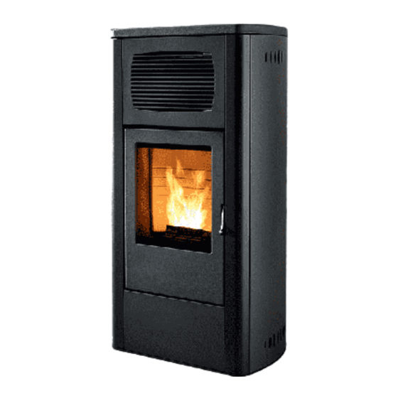
MCZ PRIMULA Installation And User Manual
Pellet stove hydro model
Hide thumbs
1
Table Of Contents
2
3
4
5
6
7
8
9
10
11
12
13
14
15
16
17
18
19
20
21
22
23
24
25
26
27
28
29
30
31
32
33
34
35
36
37
38
39
40
41
42
43
44
45
46
47
48
49
50
51
52
53
54
55
56
57
58
59
60
61
62
63
64
65
66
67
68
page
of
68
Go
/
68
Contents
Table of Contents
Bookmarks
Table of Contents
Table of Contents
Introduction
Warnings and Warranty Conditions
Installation Instructions
Technical Drawings and Characteristics
Installation and Assembly
Plumbing Connection
Plumbing Connection
Electrical Connections
Initial Start up
Menu Items
Menu Items
Preliminary Notions
Operation
Safety Devices and Alarms
Maintenance and Cleaning
Problems/Causes/Solutions
Wiring Diagram
Advertisement
Quick Links
1
Maintenance and Cleaning
2
Problems/Causes/Solutions
Download this manual
INSTALLATION AND USER GUIDE
EN
PELLET STOVE
PRIMULA
ORCHIDEA
GARDENIA
MARGHERITA
HYDRO MODEL
Translation of original instructions
Table of
Contents
Previous
Page
Next
Page
1
2
3
4
5
Advertisement
Table of Contents
Need help?
Do you have a question about the PRIMULA and is the answer not in the manual?
Ask a question
Questions and answers
Related Manuals for MCZ PRIMULA
Stove MCZ ANTHEA Installation And Use Manual
(27 pages)
Stove MCZ Polar Installation And Use Manual
(65 pages)
Stove MCZ Planet Installation And Use Manual
(62 pages)
Stove MCZ PELLET LEVEL SENSOR Use And Installation Manual
(32 pages)
Stove MCZ PHILO COMFORT AIR 14 UP! M2 Installation Manual
Sealed pellet stove (76 pages)
Stove MCZ PHILO COMFORT AIR 14 M2 Installation Manual
Sealed pellet stove (52 pages)
Stove MCZ Kaika Oyster Installation And Use Manual
Mcz kaika oyster pellet stove installation and use manual (57 pages)
Stove MCZ Veld Use And Installation
Mcz veld wood burning stove (25 pages)
Stove MCZ GARDENIA Installation And User Manual
Pellet stove hydro model (68 pages)
Stove MCZ Kama Installation And Use Manual
(42 pages)
Stove MCZ EGO AIR Use And Maintenance Manual
(54 pages)
Stove MCZ FLAT Use And Installation Manual
Comfort air made of ceramics/steatite (60 pages)
Stove MCZ VIVO 90 HYDRO 16 M1 Use And Installation Manual
Pellet insert (52 pages)
Stove MCZ HALO AIR 8 M1 Installation Manual
(64 pages)
Stove MCZ HALO AIR 8 M2 Installation Manual
Sealed pellet stove (72 pages)
Stove MCZ TECLA AIR 6 M1 Operation And Cleaning
Sealed pellet stove (72 pages)
This manual is also suitable for:
Orchidea
Gardenia
Margherita
Table of Contents
Print
Rename the bookmark
Delete bookmark?
Delete from my manuals?
Login
Sign In
OR
Sign in with Facebook
Sign in with Google
Upload manual
Upload from disk
Upload from URL


Need help?
Do you have a question about the PRIMULA and is the answer not in the manual?
Questions and answers