
Related Manuals for Kramer VS-808DS


Summary of Contents for Kramer VS-808DS
- Page 1 Kramer Electronics, Ltd. USER MANUAL Model: VS-808DS 8x8 Video Audio Matrix Switcher / Scaler...
-
Page 2: Table Of Contents
Table of Hex Codes for the Master VS-808DS Communication Protocol Figures Figure 1: VS-808DS 8x8 Video Audio Matrix Switcher / Scaler Front Panel Figure 2: Connecting the VS-808DS 8x8 Video Audio Matrix Switcher / Scaler Figure 3: Connecting a PC without using a Null-modem Adapter... - Page 3 Contents Tables Table 1: VS-808DS 8x8 Video Audio Matrix Switcher / Scaler Front Panel Features Table 2: VS-808DS 8x8 Video Audio Matrix Switcher / Scaler Rear Panel Features Table 3: Dipswitch Settings Table 4: Self Address # Dipswitch Settings Table 5: Technical Specifications of the VS-808DS...
-
Page 4: Introduction
GROUP 6: Accessories and Rack Adapters; GROUP 7: Scan Converters and Scalers; and GROUP 8: Cables and Connectors 2 Downloadable from our Web site at http://www.kramerelectronics.com 3 Download up-to-date Kramer user manuals from our Web site at http://www.kramerelectronics.com 4 The complete list of Kramer cables is on our Web site at http://www.kramerelectronics.com... - Page 5 Getting Started Video Video Recorder LCD Display Player KRAMER: SIMPLE CREATIVE TECHNOLOGY...
-
Page 6: Overview
XGA (1024x768), or WXGA (1366x768) Acceptance of PAL-B/D/G/H/I, NTSC 3.58, and NTSC 4.43 video formats The VS-808DS is housed in a 19" 2U rack-mountable enclosure and is fed from a 100-240 VAC universal switching power supply. To achieve the best performance:... -
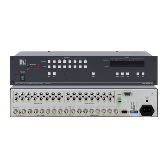
Page 7: Figure 1: Vs-808Ds 8X8 Video Audio Matrix Switcher / Scaler Front Panel
Your VS-808DS 8x8 Video Audio Matrix Switcher / Scaler Figure 1: VS-808DS 8x8 Video Audio Matrix Switcher / Scaler Front Panel KRAMER: SIMPLE CREATIVE TECHNOLOGY... -
Page 8: Table 1: Vs-808Ds 8X8 Video Audio Matrix Switcher / Scaler Front Panel Features
Your VS-808DS 8x8 Video Audio Matrix Switcher / Scaler Table 1: VS-808DS 8x8 Video Audio Matrix Switcher / Scaler Front Panel Features Feature Function IR Receiver The red LED is illuminated when receiving signals from the infra-red remote control transmitter... -
Page 9: Table 2: Vs-808Ds 8X8 Video Audio Matrix Switcher / Scaler Rear Panel Features
2 The signal that is converted via the scaled output is the input signal that is routed to output 8 3 Optional. Can be used instead of the front panel (built-in) IR receiver to remotely control the VS-808DS (only if the internal... -
Page 10: Installing On A Rack
Installing on a Rack Installing on a Rack This section describes what to do before installing on a rack and how to rack mount. -
Page 11: Connecting The Vs-808Ds
1 You do not have to connect all the inputs or all the outputs 2 Switch OFF the power on each device before connecting it to your VS-808DS. After connecting your VS-808DS, switch on its power and then switch on the power on each device 3 After connecting the power, if required, press the OUTPUT RES. -
Page 12: Figure 2: Connecting The Vs-808Ds 8X8 Video Audio Matrix Switcher / Scaler
Connecting the VS-808DS Figure 2: Connecting the VS-808DS 8x8 Video Audio Matrix Switcher / Scaler... -
Page 13: Connecting A Pc
Connecting the VS-808DS 6.1 Connecting a PC You can connect a PC (or other controller) to the VS-808DS via the RS-232 port. To connect using the Null-modem adapter provided with the machine (recommended method): Connect the RS-232 DB9 rear panel port on the VS-808DS to the... -
Page 14: Connecting Via Rs-485
Connecting the VS-808DS 6.2 Connecting via RS-485 You can control a VS-808DS unit via an RS-485 controller, or a Master Programmable Remote Control system such as the Kramer RC-3000. To connect an RC-3000 to a VS-808DS unit (see Figure 4), connect the... -
Page 15: Setting The Vs-808Ds Dipswitches
VS-808DS units are controlled by a PC or serial controller. Set the SELF ADDRESS on a VS-808DS unit via DIPS 1, 2, and 3, according to Table 4. When using a stand-alone VS-808DS unit, set the SELF ADDRESS to 1... -
Page 16: Setting The Reply Dipswitch
Setting the REPLY Dipswitch Dipswitch #5 (the REPLY dipswitch) enables or disables a reply from the VS-808DS to the PC. Enabling the reply is usually desirable, so that the controlling device “knows” that the controlled device has carried out its instructions. When an RS-485 connection is used for communication between the Matrix Switcher and the PC, dipswitch #8 should be set to OFF. -
Page 17: Operating Your Vs-808Ds
How to confirm settings (see section 7.4) How to store and recall input/output configurations (see section 7.5) How to reset the machine (see section 7.6) 7.1 Displaying the Unit Characteristics The VS-808DS 7-segment display shows the selected audio or video input switched to the marked output. -
Page 18: Choosing The Audio-Follow-Video Or Breakaway Option
7.4 Confirming Settings You can choose to work in the At Once or the Confirm mode. When the VS-808DS operates in the At Once mode, pressing an OUTPUT-INPUT combination implements the switch immediately. In the Confirm mode, the TAKE button must be pressed to authorize the switch. -
Page 19: Toggling Between The At Once And Confirm Modes
Operating Your VS-808DS The Confirm Mode In the Confirm mode: You can key-in several actions and then confirm them by pressing the TAKE button, which simultaneously activate the multiple switches Every action requires user confirmation, to protect against erroneous switching... -
Page 20: Storing/Recalling Input/Output Configurations
Operating Your VS-808DS 7.5 Storing/Recalling Input/Output Configurations You can store and recall up to 8 input/output configurations (or setups) in non-volatile memory, using the INPUT SELECTOR buttons 1 to 8. 7.5.1 Storing an Input/Output Configuration To store the current status in memory, do the following: 1. -
Page 21: Technical Specifications
Technical Specifications Technical Specifications of the VS-808DS: Table 5 includes the technical specifications Table 5: Technical Specifications of the VS-808DS INPUTS: 8 composite video, 1Vpp/75 on BNC connectors 1 Sync/Video Genlock 1Vpp/75 with sync select switch 8 audio stereo on RCA connectors, 4dBm nominal... -
Page 22: Table Of Hex Codes For The Master Vs-808Ds
Table of Hex Codes for the Master VS-808DS Table of Hex Codes for the Master VS-808DS Table 6 shows the “HEX” codes for switching the master VS-808DS. Table 6: Hex Codes for Switching the Master VS-808DS IN 1 IN 2... -
Page 23: Communication Protocol
Communication Protocol 10 Communication Protocol The VS-808DS is compatible with Kramer’s Protocol 2000 (version 0.48) (below). This RS-232/RS-485 communication protocol uses four bytes of information as defined below. For RS-232, a null-modem connection between the machine and controller is used. The default data rate is 9600 baud, with no parity, 8 data bits and 1 stop bit. -
Page 24: Table 8: Instruction Codes
Communication Protocol Table 8: Instruction Codes Note: All values in the table are decimal, unless otherwise stated. INSTRUCTION DEFINITION FOR SPECIFIC INSTRUCTION NOTE DESCRIPTION INPUT OUTPUT RESET VIDEO SWITCH VIDEO Set equal to video input Set equal to video output which is 2, 15 which is to be switched to be switched... - Page 25 Memory address Data AUDIO PARAMETER INPUT Bit: 0 - Gain SETTINGS FOR I0=input; 1=output 1 - Bass INSTRUCTIONS 22, 24, 25 I1 - Left 2 - Treble I2 - Right 3 - Midrange 4 - Mix On KRAMER: SIMPLE CREATIVE TECHNOLOGY...
- Page 26 Communication Protocol INSTRUCTION DEFINITION FOR SPECIFIC INSTRUCTION NOTE DESCRIPTION INPUT OUTPUT VIDEO PARAMETER SETTINGS 1 – Input 0 - video gain FOR INSTRUCTIONS 21, 23, 26 2 – Output 1 - contrast 2 - brightness 3 - colour 4 - hue 5 - H-phase 6 - V-position MEDIA CONTROL...
- Page 27 NOTE 17 – For clean switching of RGBHV video, the “ seamless switching” option may be used. The blanking period for the transition of the RGB sources may be set in this case, in steps of 25 milliseconds. For example, to set for 350ms blanking time (14 steps), send HEX codes KRAMER: SIMPLE CREATIVE TECHNOLOGY...
- Page 28 Communication Protocol NOTE 18 – Delayed execution allows switching after a delay dictated by RS-232. To do this, the user sends instruction 7 with the “ Set for delayed switch” option (64dec) before sending the switch command (instruction 1) or pressing via front panel. The switch is not executed (unless timed-out) until the “...
- Page 29 KRAMER: SIMPLE CREATIVE TECHNOLOGY...
- Page 30 For the latest information on our products and a list of Kramer distributors, visit our Web site: www.kramerelectronics.com, where updates to this user manual may be found. We welcome your questions, comments and feedback. Safety Warning: Disconnect the unit from the power supply before opening/servicing.
Need help?
Do you have a question about the VS-808DS and is the answer not in the manual?
Questions and answers