
Related Manuals for Tektronix PWS2185


Summary of Contents for Tektronix PWS2185
- Page 1 Test Equipment Depot - 800.517.8431 - 99 Washington Street Melrose, MA 02176 - TestEquipmentDepot.com PWS2185, PWS2323, PWS2326, and PWS2721 Linear DC Power Supplies User Manual *P071275100* 071-2751-00...
- Page 3 PWS2185, PWS2323, PWS2326, and PWS2721 Linear DC Power Supplies User Manual...
- Page 4 Copyright © Tektronix. All rights reserved. Licensed software products are owned by Tektronix or its subsidiaries or suppliers, and are protected by national copyright laws and international treaty provisions. Tektronix products are covered by U.S. and foreign patents, issued and pending. Information in this publication supersedes that in all previously published material.
- Page 5 Warranty Tektronix warrants that the product will be free from defects in materials and workmanship for a period of three (3) years from the date of original purchase from an authorized Tektronix distributor. If the product proves defective during this warranty period, Tektronix, at its option, either will repair the defective product without charge for parts and labor, or will provide a replacement in exchange for the defective product.
-
Page 7: Table Of Contents
Front-panel Operation......................Index PWS2185, PWS2323, PWS2326, and PWS2721 User Manual... - Page 8 Table of Contents PWS2185, PWS2323, PWS2326, and PWS2721 User Manual...
-
Page 9: General Safety Summary
Do not operate in an explosive atmosphere. Keep product surfaces clean and dry. Provide proper ventilation. Refer to the manual’s installation instructions for details on installing the product so it has proper ventilation. PWS2185, PWS2323, PWS2326, and PWS2721 User Manual... - Page 10 DANGER indicates an injury hazard immediately accessible as you read the marking. WARNING indicates an injury hazard not immediately accessible as you read the marking. CAUTION indicates a hazard to property including the product. The following symbol(s) may appear on the product: PWS2185, PWS2323, PWS2326, and PWS2721 User Manual...
-
Page 11: Compliance Information
Under the factory default settings, output voltage and current limit values will be restored to the previous settings, but output state will be set to off. Change the user preferences if restoration of previous output state upon restoration of AC input power is desired. PWS2185, PWS2323, PWS2326, and PWS2721 User Manual... - Page 12 CISPR 11:2003. Radiated and Conducted Emissions, Group 1, Class A, in accordance with EN 61326-1:2006. Australia / New Zealand contact. Baker & McKenzie Level 27, AMP Centre 50 Bridge Street Sydney NSW 2000, Australia PWS2185, PWS2323, PWS2326, and PWS2721 User Manual...
-
Page 13: Safety Compliance
These are sheltered locations where neither temperature nor humidity is controlled. The area is protected from direct sunshine, rain, or direct wind. Pollution Degree 4. Pollution that generates persistent conductivity through conductive dust, rain, or snow. Typical outdoor locations. PWS2185, PWS2323, PWS2326, and PWS2721 User Manual... - Page 14 Measurement Category II. For measurements performed on circuits directly connected to the low-voltage installation. Measurement Category I. For measurements performed on circuits not directly connected to MAINS. Overvoltage Category Overvoltage Category II (as defined in IEC 61010-1) viii PWS2185, PWS2323, PWS2326, and PWS2721 User Manual...
-
Page 15: Environmental Considerations
This symbol indicates that this product complies with the applicable European Union requirements according to Directives 2002/96/EC and 2006/66/EC on waste electrical and electronic equipment (WEEE) and batteries. For information about recycling options, check the Support/Service section of the Tektronix Web site. -
Page 16: Preface
DC power supply. 18 V, 5 A, 1 channel PWS2323 DC power supply. 32 V, 3 A, 1 channel PWS2326 DC power supply. 32 V, 6 A, 1 channel PWS2721 DC power supply. 72 V, 1.5 A, 1 channel PWS2185, PWS2323, PWS2326, and PWS2721 User Manual... -
Page 17: Getting Started
Getting Started Standard Accessories Tektronix part Accessory number PWS2185, PWS2323, PWS2326, and PWS2721 Power Supply User Manual (available in 10 071-2751-XX to languages) Contains safety and installation information. 071-2760-XX Power Cord: based upon the international power option (See page 1,... -
Page 18: Specifications
Getting Started Specifications For more specifications, refer to the PWS2185, PWS2323, PWS2326, and PWS2721 Technical Reference. Table 2: Electrical ratings for the power connection Line Selector Model Switch Setting Frequency Fuse Rating Max Power PWS2185 110 V / 220 V... -
Page 19: Installing The System
Unpack the instrument and check that you received all the items listed as standard accessories. Check that you also received any other accessories that you ordered with your instrument. Check the Tektronix Web site for the most current information. To verify that the power supply is ready to use, follow these procedures:... - Page 20 If you set the line selection to 110 V, use a 5 A, TH 250 V fuse. If you set the line selection to 220 V, use a 2.5 A, TH 250 V fuse. 4. If you need more help, contact Tektronix. PWS2185, PWS2323, PWS2326, and PWS2721 User Manual...
- Page 21 8. Push the output On/Off button to enable the output. The CC message should be lit. 9. Push I-set and use the numeric keys and Enter button to set the current value to 0 A. Check if the displayed current value is approximately 0 A. PWS2185, PWS2323, PWS2326, and PWS2721 User Manual...
-
Page 22: Cleaning
To avoid damage to the surface of the power supply, do not use any abrasive or chemical cleaning agents. CAUTION. Avoid getting moisture inside the unit during external cleaning. Use only enough cleaning solution to dampen the cloth or swab. PWS2185, PWS2323, PWS2326, and PWS2721 User Manual... -
Page 23: Operating Basics
Saves the present settings to a specified setup memory location (1 to 20). Select the memory location with the multipurpose knob, the up or down arrow keys, or the numeric keypad. The power supply saves the settings after you push Enter. PWS2185, PWS2323, PWS2326, and PWS2721 User Manual... - Page 24 Turns on or off a beeper sound when you push a button or press a key. “On” enables the key sound. “Off” disables it. Sys Info Provides instrument information including model number, serial number, and software version. Display messages Symbol Description The power supply output is off PWS2185, PWS2323, PWS2326, and PWS2721 User Manual...
-
Page 25: Rear Panel At A Glance
Front panel controls are locked. Enter password to unlock. Rear Panel at a Glance 1. Cooling vents 2. 110 V/220 V power connector 3. Factory test port CAUTION. Unauthorized use of the factory test port could damage this product. PWS2185, PWS2323, PWS2326, and PWS2721 User Manual... -
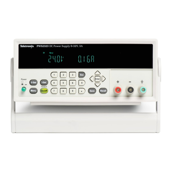
Page 26: Front-Panel Operation
If the front panel was locked with a password, enter the correct password after you push one of the front panel buttons, then you can change the settings. NOTE. To cancel a function operation (V-set, I-set, Save, and Recall), push the Esc button. PWS2185, PWS2323, PWS2326, and PWS2721 User Manual... - Page 27 5. Push the up arrow button to select Yes and push Enter to enable the default settings. The default settings are: Output On/Off = OFF V-Set = 1.000V I-Set = 0.1000A Max Volt Set = Off Save Last = On Out Recall = On Key Beep = Off PWS2185, PWS2323, PWS2326, and PWS2721 User Manual...
- Page 28 5. Push Esc to exit the menu. 6. Push V-Set. 7. Use the numeric keys or the arrow keys to change the voltage value. The value must be less than the maximum voltage output. PWS2185, PWS2323, PWS2326, and PWS2721 User Manual...
- Page 29 2. Use the down arrow key to select Save Last. 3. Push Enter. 4. Use the arrow keys to select On or Off. 5. Push Enter. 6. Push Esc to exit the menu system. NOTE. The default selection is set to On. PWS2185, PWS2323, PWS2326, and PWS2721 User Manual...
- Page 30 2. Use the down arrow key to select Key Beep. 3. Push Enter. 4. Use the arrow keys to select On or Off. 5. Push Enter. 6. Push Esc to exit the menu system. NOTE. The default selection is set to Off. PWS2185, PWS2323, PWS2326, and PWS2721 User Manual...
-
Page 31: Index
Front panel, 10 recalling setups, 12 Front panel indicators and buttons, 7 saving setups, 12 V-set button, 7 voltage limit adjustment, 12 Voltage limit adjustment, 12 Optional accessories, 1 Volts display, 7 Options, 1 PWS2185, PWS2323, PWS2326, and PWS2721 User Manual...
Need help?
Do you have a question about the PWS2185 and is the answer not in the manual?
Questions and answers