Advertisement
Quick Links
T M 1 1 - 6 6 2 5 - 2 9 7 8 - 1 4
T E C H N I C A L
M A N U A L
OPERATOR'S, ORGANIZATIONAL,
DIRECT SUPPORT AND GENERAL SUPPORT
MAINTENANCE MANUAL
FOR
P O W E R S U P P L Y P P - 7 5 4 9 / U
( T E K T R O N I X M O D E L 1 1 0 6 )
( N S N 6 1 3 0 - 0 1 - 0 1 8 - 1 2 2 6 )
H E A D Q U A R T E R S , D E P A R T M E N T O F T H E A R M Y
1 8
F E B R U A R Y
1 9 8 2
Advertisement

Related Manuals for Tektronix 1106


Summary of Contents for Tektronix 1106
- Page 1 T M 1 1 - 6 6 2 5 - 2 9 7 8 - 1 4 T E C H N I C A L M A N U A L OPERATOR’S, ORGANIZATIONAL, DIRECT SUPPORT AND GENERAL SUPPORT MAINTENANCE MANUAL P O W E R S U P P L Y P P - 7 5 4 9 / U ( T E K T R O N I X M O D E L 1 1 0 6 ) ( N S N 6 1 3 0 - 0 1 - 0 1 8 - 1 2 2 6 )
- Page 2 SAFETY STEPS TO FOLLOW IF SOMEONE IS THE VICTIM OF ELECTRICAL SHOCK DO NOT TRY TO PULL OR GRAB THE INDIVIDUAL IF POSSIBLE, TURN OFF THE ELECTRICAL POWER IF YOU CANNOT TURN OFF THE ELECTRICAL POWER, PULL, PUSH, OR LIFT THE PERSON TO SAFETY USING A WOODEN POLE OR A ROPE OR SOME OTHER INSULATING MATERIAL SEND FOR HELP AS SOON AS POSSIBLE...
- Page 3 This manual includes copyright material reproduced by permission of the Tektronix, Inc. TM11-6625-2978-14 HEADQUARTERS E C H N I C A L A N U A L DEPARTMENT OF THE ARMY , DC, 18 February 1982 . 11-6625-2978-14 ASHINGTON OPERATOR’S, ORGANIZATIONAL, DIRECT SUPPORT,...
-
Page 4: Table Of Contents
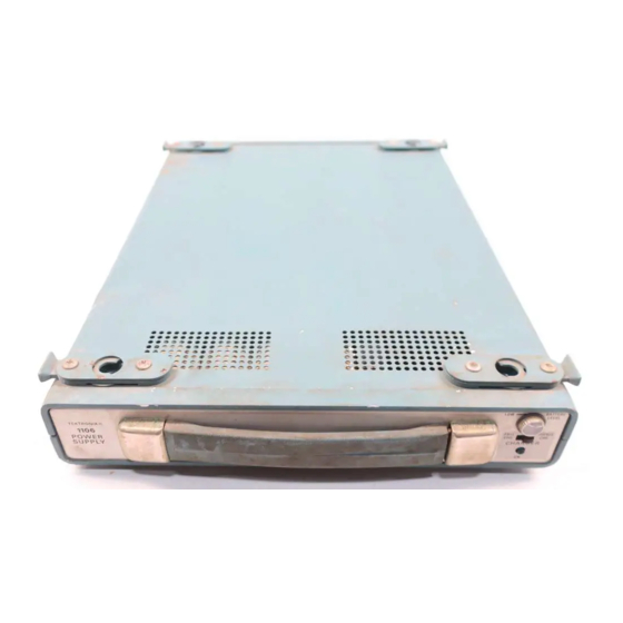
Page Paragraph REFERENCES ..............PPENDIX MAINTENANCE ALLOCATION . - Page 5 Figure 1-1. Power Supply PP-7549/U (1106 Battery Pack) Being Instlled Under a Portable Oscilloscope.
- Page 6 Power Supply PP-7549/U is a dc power source for operating portable Oscilloscope OS-261/U 1-9. Use Option (Tektronix Model 475 Option 7) away from ac power a. The separate battery pack capability permits a sources. Power Supply PP-7549/U is sold com- choice of battery operation or ac line operation.
- Page 7 b. Refer to the oscilloscope technical manual for c. Battery Operating Time. Approximately 140 information regarding input power switch position watt-hours from fully-charged batteries. when changing to or from battery pack operation. d. Battery Charge Time. 14 to 16 hours (0° C to 40°...
- Page 8 Oscilloscope battery pack from one working area to the next. OS-261 (Tektronix Model 475 Option 7). Set the d. It may be advantageous to use the battery oscilloscope on the battery pack and observe that pack and the oscilloscope as separate units as each the oscilloscope feet seat properly in the clamps.
- Page 9 CHAPTER 3 OPERATING INSTRUCTIONS Section I. FUNCTION OF CONTROLS AND CONNECTORS 3-1. Battery Level tain fully-charged batteries. b. ON Position. Lamp indicates charger is on. Meter indicates the approximate state of charge of Charging occurs as long as the battery pack is con- the batteries while under load.
- Page 10 Table 3-1. Typical Battery Charge Capacity (referenced to charge-discharge at +20° C to +30° C) Operating Temperature Charge Temperature +55° C C to +30° C -15° C + 2 0 ° 0° C 100% +20° C to +30° C +40° C c.
- Page 11 310. Battery Charge Level b. Charge retention characteristics of nickel- cadmium batteries vary with the storage tem- a. Meter indication of battery charge level may be perature and humidity. The battery pack may be false during the first several minutes of battery stored at ambient temperatures between —40°...
- Page 12 CHAPTER THEORY OF OPERATION Section I. CIRCUIT DESCRIPTION 4-1. General b. At low line, CR111 and CR112 are reverse biased. An increase in line voltage increases the a. The battery pack provides a 24 Vdc power potential from the -DC OUT line to the collector of source.
- Page 13 Section Il. OPERATION UNDER UNUSUAL CONDITIONS 4-6. Operation in Tropical Climates 4-5. Operation in Arctic Climates In tropical climates, electronic equipment may be in- Subzero temperatures and climatic conditions associated with cold weather may hamper the ef- stalled in tents, huts or, when necessary, in un- derground dugouts.
- Page 14 The specified must be used. Other types may not func- Tektronix Field Representative or Office should be tion properly. They may prove to be a hazard to the consulted before cells are replaced, if the warranty is instrument and to personnel.
- Page 15 variation in input voltage as may exist in certain pack should be charged for 24 hours after cells are conditions or geographical areas. The wires on tran- replaced. sformer T101 may be changed to accept line b. All cells in the battery pack should be made by variation.
- Page 16 CHAPTER 6 CALIBRATION Section I. GENERAL 6-1. Terms and Definition b. Calibration, in accordance with AR 750-25-1 (US Army Calibration System), is a periodic check a. Calibration, in accordance with maintenance of the total accuracy of each parameter as compared practices, is the checking of voltages, current, to calibrated standards at a ratio of 4 to 1.
- Page 17 Figure 6-1. Battery Pack PP-75/U, Exploded View. WARNING curate setting of the meter zero. Because Dangerous potential and high current this type of power supply may not be capabilities exist at several points. available, an alternate method is given. Disconnect power cord, remove fuse The accuracy of the equipment required F131, and unsolder batteries before depends on how critically the user wants...
- Page 18 /ς∆Χ and 5,000 /ςΑΧ m u l t i m e t e r . Ω Ω Voltmeter: 20,000 Voltage readings will vary with line voltage and battery charge level. Battery charged Line Selector: Correct line voltage Mode Switch: FULL CHG Figure 6-2.
- Page 19 C I R C U I T B O A R D I L L U S T R A T I O N , D I A G R A M , A N D P A R T S L I S T S Symbols Electrical components shown on the diagrams are in the following units unless noted otherwise: Capacitors = Values one or greater are in picofarads (pF).
- Page 20 N O T E : DENOTES COMMON NEGATIVE RETURN Figure 6-4. Battery Pack PP-7649/U, Schematic Diagram.
-
Page 21: References
APPENDIX A REFERENCES Index of Technical Publications. DA Pam 310-4 TB 43-180 Calibration Requirements for the Maintenance of Army Materiel. TB 43-0118 Field Instructions For Painting and Preserving Electronics Command Equip- ment Including Camouflage Pattern Painting of Electrical Equipment Shelters. TM 11-6130-351-14 Operator’s, Organizational, Direct Support, and General Support Main- tenance Manual Including Repair Parts and Special Tools Lists (Including... -
Page 22: Maintenance Allocation
APPENDIX B MAINTENANCE ALLOCATION Section I. INTRODUCTION vices (inspect, test, service, adjust, align, calibrate, B-1. General replace) or other maintenance actions (welding, grin- This appendix provides a summary of the main- ding, riveting, straightening, facing, remachining, tenance operations for the PP-7549/U. It authorizes or resurfacing) to restore serviceability to an item categories of maintenance for specific maintenance by correcting specific damage, fault, malfunction, or... -
Page 23: Ection
maintenance function vary at different maintenance B-4. Tools and Test Equipment Requirements categories, appropriate “work time” figures will be (See III) shown for each category. The number of task-hours a. Tool or Test Equipment Reference Code. The specified by the “work time” figure represents the numbers in this column coincide with the numbers average time required to restore an item (assembly, used in the tools and equipment column of the MAC. -
Page 24: Maintenance Allocation Chart
TM 11-6625-2978-14 SECTION II MAINTENANCE ALLOCATION CHART POWER SUPPLY PP-7549/U MAINTENANCE CATEGORY TOOLS GROUP C O M P O N E N T / A S S E M B L Y MAINTENANCE REMARKS NUMBER FUNCTION EQPT. Inspect POWER SUPPLY PP-7549/U 1 thru 3 Test 1 thru 3... -
Page 25: Tool And Test Equipment Requirements
TM 11-6625-2978-14 SECTION TOOL TEST EQUIPMENT REQUIREMENTS F O R POWER SUPPLY PP-7549/U TOOL TEST M A I N T E N A N C E NATIONAL/NATO N O M E N C L A T U R E E Q U I P M E N T TOOL NUMBER C A T E G O R Y... - Page 30 THE METRIC SYSTEM AND EQUIVALENTS...
- Page 31 PIN: 050633-000...
- Page 32 This fine document... Was brought to you by me: Liberated Manuals -- free army and government manuals Why do I do it? I am tired of sleazy CD-ROM sellers, who take publicly available information, slap “watermarks” and other junk on it, and sell it. Those masters of search engine manipulation make sure that their sites that sell free information, come up first in search engines.
Need help?
Do you have a question about the 1106 and is the answer not in the manual?
Questions and answers