Table of Contents
Advertisement
Quick Links
Advertisement
Table of Contents

Related Manuals for Tektronix PS 503


Summary of Contents for Tektronix PS 503
- Page 1 TEKTRONIX INSTRUCTION MANUAL...
- Page 2 INSTRUCTION MANUAL DUAL POWER SUPPLY PS 503 Serial Number _________________________ Tektronix, Inc. P.O. Box 500 Beaverton, Oregon 97005 Phone: 644-0161 -9- Cables: Tektronix 070-1303-00...
- Page 3 TEKTRONIX Field Engineer or representative. All requests for repairs and replacement parts should be directed to the TEKTRONIX Field Office or representative in your area. This will assure you the fastest possible service. Please include the instrument Type Number or Part Number and Serial Number with all requests for parts or service.
-
Page 4: Table Of Contents
PS 503 TABLE OF CONTENTS SECTION 1 OPERATING INSTRUCTIONS Page Description Operation Operating Considerations Electrical Characteristics SECTION 2 THEORY OF OPERATION SECTION 3 SERVICING INFORMATION Calibration Adjustment Procedure Diagrams & Parts Lists... - Page 5 PS 503...
-
Page 6: Operating Instructions
DESCRIPTION NOTE It is recommended that the Power Module be turned The PS 503 is a dual 0 to 20 V DC constant-voltage, off before inserting or removing the PS 503. Arcing current-limited, floating power supply that plugs into a at the connector terminals can reduce connector life. - Page 7 For example, Fig. 1-1 shows the stair-step power and operates as a constant voltage source with output from the PS 503 when a variable load (R L ) is output current variable with the load. Then, at approxi ...
-
Page 8: Operating Considerations
One supply should be set for the desired output voltage and the other for a slightly higher voltage. The supply set The outputs of two or more PS 503 's can be for the desired voltage will then become a constant voltage connected in series as shown in Fig. - Page 9 (or other instruments connected to the connections are made to either the chassis or ground. The load) produce a voltage across the PS 503 terminals which supply can thus be used as a positive or negative supply by...
-
Page 10: Electrical Characteristics
Operating Instructions — PS 503 STABILITY: 0.1% + 5 mV or less drift in 8 hours at ELECTRICAL CHARACTERISTICS constant line, load and temperature. Performance Conditions The electrical characteristics are valid only if the TRANSIENT RECOVERY TIME: 20 µs or less for a... -
Page 12: Theory Of Operation
(see Fig. 2-1). The amplifier with the lower parallel with + and — VOLTS potentiometers R32 and output voltage at pin 6 will cause its associated diode To S30B i о R30B Fig. 2-1. Simplified block diagram of PS 503... - Page 13 Theory of Operation — PS 503 (CR40 or CR71) to conduct, which eventually reverse With no load connected to the output terminals, = ∞ , l L = 0 and E = S V L / the front-panel voltage biases the other diode. A portion of the current available limit setting (see Fig.
-
Page 14: Servicing Information
Section 1. Preparation Test Equipment Required 1. Remove the cover from the left side of the PS 503 and, if necessary, blow off accumulated dust with low- The following test equipment and accessories, or the pressure compressed air. -
Page 15: Adjustment Procedure
Load Compensation (R18/R28) 3. If the extender is not used, remove the Power Module cabinet cover to gain access to the PS 503 internal adjust 1. Connect the 50 Ω, 8 W Load Resistor across the ment. - Page 16 TABLE 3-1 Rear Connector Pin Assignments Left (A) Right (B) Pin No. No Connection 27 and 28 No Connection -Non-Inverting Input to U170 +Non-lnverting Input to U70 -Non-Inverting Input to U140 +Non-lnverting Input to U40 via R35 via R135 Reference Common Reference Common +Sense (R81 ) —...
- Page 17 INTERNAL ADJUSTMENTS...
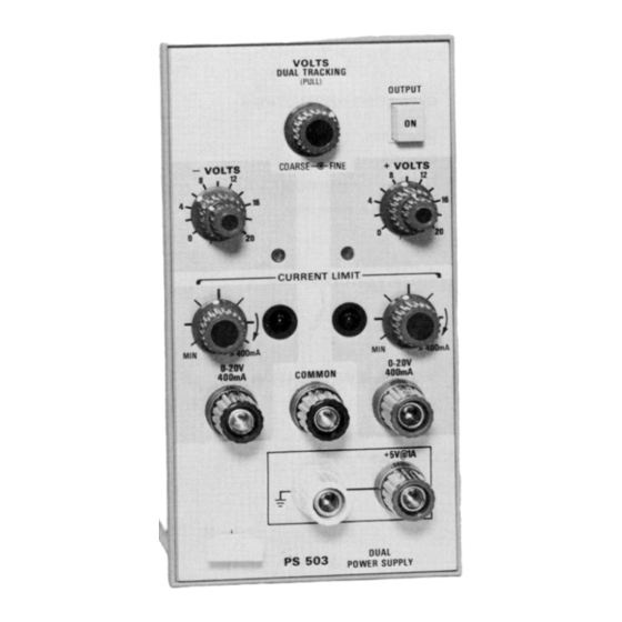
- Page 18 OUTPUT Pushbutton When pressed, applies power from Power Module to the PS 503. CURRENT LIMIT Controls and Indicators Continuously variable controls that select the + and — output current limit from 0 to at least 400 mA.
- Page 20 PS 503 PS 503 COMPONENT LOCATIONS...
- Page 21 PS 503 ELECTRICAL PARTS LIST Replacement parts should be ordered from the Tektronix Field Office or Representative in your area. Changes to Tektronix products give you the benefit of improved circuits and components. Please include the instrument type number and serial number with each order for parts or service.
- Page 22 Electrical Parts List — PS 503 ELECTRICAL PARTS LIST fcont) Grid Tektronix Serial/Model No. Part No. Disc Description DIODES Ccont) CR171 152-0141-02 Silicon, replaceable by 1N4152 CR174 152-0141-02 Silicon, replaceable by 1N4152 152-0304-00 Zener, replaceable by 1N968B, 0.4 W, 20 V, 5%...
- Page 23 Electrical Parts List — PS 503 ELECTRICAL PARTS LIST (cont) Grid Tektronix Serial/Model No. Part No. Disc Description RESISTORS (cont) 10 kΩ, 1/4 W, 5% 315-0103-00 3 kΩ, 1/2 W, 5% 301-0302-00 315-0510-00 51 Ω, 1/4 W, 57 315-0301-00 300 Ω, 1/4 W, 5% 315-0512-00 5.1 kΩ, 1/4 W, 5%...
- Page 25 PS 503...
- Page 27 PS 503 MECHANICAL PARTS LIST Replacement parts should be ordered from the Tektronix Field Office or Representative in your area. Changes to Tektronix products give you the benefit of improved circuits and components. Please include the instrument type number and serial number with each order for parts or service.
- Page 28 Mechanical Parts List — PS 503 FIGURE 1 EXPLODED (cont) Fig. & Index Tektronix Serial/Model No. Description Part No. DiSC 2 3 4 5 1-19 129-0064-01 POST, binding, red (J50 & J5) mounting hardware for each: (not included w/post) 210-0457-00 NUT, keps, 6-32 x 0.312 inch...
- Page 29 Mechanical Parts List — PS 503 FIGURE 1 EXPLODED (cont) Fig. & Index Tektronix Serial/Model No. Description Part No. Disc У 2 3 4 5 SHIELD, subpanel rear 1-47 337-1638-00 SHAFT, extension, 7.781 inches long 384-1058-00 CIRCUIT BOARD ASSEMBLY — MAIN (See Al electrical list)
- Page 33 CARTON ASSEMBLY (Part No. 065-0151-00) Fig. & Index Tektronix Serial/Model No. Description Part No. Disc 2 3 4 5 065-0151-00 CARTON ASSEMBLY carton assembly includes 004-0282-00 FRAME 004-0243-00 END CAP, front 004-0242-00 END CAP, rear 004-1093-00 004-0612-00 CARTON...
- Page 34 STANDARD ACCESSORIES Fig. & Index Tektronix Serial/Model No. Part No. Disc у 2 3 4 5 Description 070-1303-00 MANUAL, instruction (not shown) PS 503 DUAL POWER SUPPLY...
- Page 35 MANUAL CHANGE INFORMATION At Tektronix, we continually strive to keep up with latest electronic developments by adding circuit and component improvements to our instruments as soon as they are devel oped and tested. Sometimes, due to printing and shipping requirements, we can't get these changes immediately into printed manuals.
- Page 37 PS 503 EFF SN B050000-up ELECTRICAL PARTS LIST CHANGE CHANGE T O : 152-0141-02 Silicon, replaceable by 1N4152 CR40 Silicon, replaceable by 1N4152 CR 140 152-0141-02 M21, 612/374...
Need help?
Do you have a question about the PS 503 and is the answer not in the manual?
Questions and answers