Table of Contents
Advertisement
Quick Links
Advertisement
Table of Contents

Related Manuals for Star DP8340 SERIES


Summary of Contents for Star DP8340 SERIES
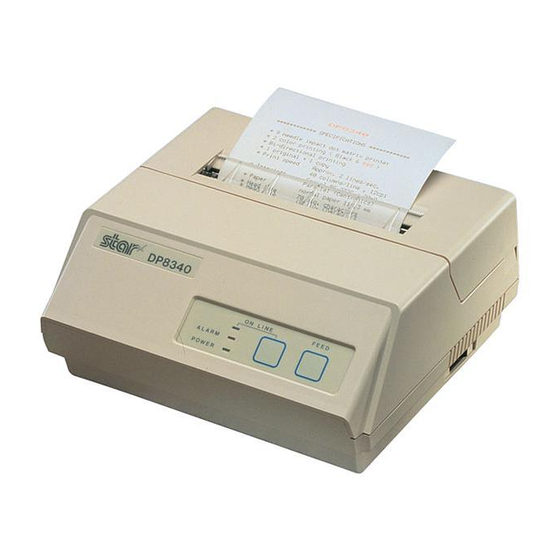
- Page 1 DOT MATRIX PRINTER DP8340 SERIES [SERIAL INTERFACE] USERS MANUAL...
-
Page 2: Trademark Acknowledgments
DP8340: Star Micronics Co. Ltd. Notice • All rights reserved. Reproduction of any part of this manual in any form whatsoever, without STAR’s express permission, is strictly forbidden. • The contents of this manual are subject to change without notice. -
Page 3: Table Of Contents
TABLE OF CONTENTS 1. OUTLINE ....................1 2. UNPACKING AND INSTALLATION ..........2 2-1. Unpacking ..................2 2-2. Installation of Paper Holders and Re-Roll Prevention Guard (Only Model DP8340F) ............... 3 2-3. Handling Notes................4 3. PART IDENTIFICATION AND NOMENCLATURE ......5 3-1. - Page 4 8. INTERFACE FOR MODEL DP8340-D (D-SUB 25 PIN CONNECTOR) ............28 8-1. Interface Specifications .............. 28 8-2. Interface Circuit ................. 29 8-2-1. RS-232C ................29 8-2-2. Current Loop ..............29 8-3. Setting of the DIP Switches ............30 8-3-1. DIP-SW 1 ................ 30 8-3-2.
-
Page 5: Outline
1. OUTLINE The DP8340 series of serial dot matrix printers is for use in ECR, POS, electronic instruments, banking machines and computer peripheral equipment. The DP8340 series include the following features; 2 color printing (Red and Black) High-speed bidirectional printing (2 line/sec, 40 columns per line) -
Page 6: Unpacking And Installation
2. UNPACKING AND INSTALLATION 2-1. Unpacking After opening the box, check if all necessary accessories are included. (A) Printer 1 Printer 5 Ink Ribbon 2 User’s Manual 6 DIP Switch Cover 3 Paper Holders 7 Ferrite Core (EU only) 4 Re-Roll Prevention Guard (B) Power Supply Unit 1 Power Supply Unit 2 User’s Manual... -
Page 7: Installation Of Paper Holders And Re-Roll Prevention Guard (Only Model Dp8340F)
2-2. Installation of Paper Holders and Re-Roll Prevention Guard (Only Model DP8340F) Install the Paper Holders in the outermost holes in the rear of the printer. Figure 2-2. Installation of Paper Holders – 3 –... -
Page 8: Handling Notes
Install the Re-Roll Prevention Wire in the holes of the printer cover. Twisting the Wire as shown in the figure below, will make the installation easier. Figure 2-3. Installation of Re-Roll Prevention 2-3. Handling Notes (1) Install the printer near an easily accessible socket-outlet. (2) Place the unit on a flat and stable surface for operation. -
Page 9: Part Identification And Nomenclature
3. PART IDENTIFICATION AND NOMENCLATURE 3-1. Power Supply Unit DC Power Connector (Output) Shape of AC Power plug will vary according to destinations. Figure 3-1. Power Supply Unit – 5 –... -
Page 10: Printer
3-2. Printer Figure 3-2. Printer: Front View Figure 3-3. Printer: Rear View – 6 –... -
Page 11: Part Functional Description
3-3. Part Functional Description (1) AC Power Plug Connect to an outlet of the specified voltage. (2) DC Power Outlet Supplies DC 12V power to the printer. (3) Printer Cover Protects the printer against dust and reduces noise. (4) POWER Lamp Lights up (green LED) when power is on. -
Page 12: Installation Of Ink Ribbon And Paper
4. INSTALLATION OF INK RIBBON AND PAPER 4-1. Installation of Ink Ribbon (1) Turn power off, lift the Printer Cover up and remove it. Note: Be careful not to touch the print head immediately after printing, because it can get very hot. Figure 4-1. -
Page 13: Removal Of Ink Ribbon
Figure 4-2. Installation of Ink Ribbon Figure 4-3. Ribbon Spools 4-2. Removal of Ink Ribbon Hold the spool and lift gently, rotating it until the ribbon sags. Push the ribbon detecting lever out, lift the spool until it comes off the shaft. Remove the second spool in a similar manner. -
Page 14: Paper Insertion
4-3. Paper Insertion 4-3-1. Model DP8340F (1) Cut the Roll Paper end straight and square. Hold the roll so that the paper comes from the bottom. (2) Attach the Roll Paper to the Holders Paper by slipping one side of the roll onto the Hub and pulling the other Hub out to allow the roll to slip in place. -
Page 15: Model Dp8340S
4-3-2. Model DP8340S Make a straight cut along the top of the paper, about 1/4 inch away from the sprocket holes, (as shown in the figure). If there is perforation, cut the paper on the perforation. Insert the paper squarely into the paper insertion slot until the ALARM lamp goes out. -
Page 16: Paper Removal
4-4. Paper Removal Cut the paper close to the slot and use the feed button until paper has passed completely through the printer. Note: Do not try to remove the paper by hand as it could become crooked and get jammed inside the printer. –... -
Page 17: Control Codes
5. CONTROL CODES CODE (0A) Print and line feed instruction FUNCTION The LF code causes the data in the line buffer to be printed, OUTLINE followed by a single line feed. When the line buffer is empty, only the feed takes place. CODE (0D) Print and line feed instruction... - Page 18 CODE (0F) FUNCTION Inverted print instruction This function causes the printing to be inverted. This code OUTLINE must be received at the beginning of a line. If this code is received anywhere other than at the beginning of a line, it is disregarded.
- Page 19 ESC a n CODE (1B) (61) n-line feed FUNCTION After printing the data in the current line, n lines are fed by this OUTLINE code. The value of n ranges from 1 to 120. ESC C n CODE (1B) (43) FUNCTION Sets page length in lines This code sets the length of a page to n lines.
- Page 20 ESC @ CODE (1B) (40) Printer initialization FUNCTION All printing conditions except ESC BEL n , the line buffer OUTLINE and data buffer are set to the power on default condition. ESC BEL n CODE (1B) (07) Sets peripheral unit drive pulse duration. FUNCTION This command sets the pulse duration for peripheral unit OUTLINE...
- Page 21 CODE (1C) Trigger peripheral unit drive (immediate) FUNCTION Causes a peripheral drive pulse to be generated immediately OUTLINE CODE (05) Enquiry FUNCTION When this code is received, the printer outputs status data. OUTLINE If it is input after text data input in the STX-ETX mode, the printer outputs status data and the check byte.
-
Page 22: Character Code List
Character Code List Character Code Function 1 LF (0A)H Print and line feed instruction 2 CR (0D)H Print and line feed instruction (same as LF) 3 SO (0E)H Expanded character instruction 4 DC4 (14)H Expanded character release 5 ESC-1 (1B)H (2D)H(01)H Underline instruction (1B)H (2D)H (31)H 6 ESC-0... -
Page 23: General Specifications
6. GENERAL SPECIFICATIONS Printing method Serial impact dot matrix printing, 9 wires Number of print columns 40 columns, 12 CPI Print speed Approx. 2 lines/sec Print direction Bi-directional Line spacing 1/6 inch Paper feed method Friction Feed or Sprocket-feed Paper feed speed Approx. - Page 24 Ink ribbon specification Color Black and red Ribbon material Nylon (#40 denier) Ribbon size 13mm 6m Spool 13mm (width), 35mm in diameter (two spool) Recommended ribbon SF-03BR (manufactured by Fuji Kagakushi Kogyo Co., Ltd.) or approved equivalent. Operating conditions Temperature +5˚C —...
- Page 25 Figure 6-3. External Dimensions (Printer) 36mm 120mm 2.0m Shape of AC Power plug will vary according to destinations. Figure 6-4. External Dimensions (Power Supply Unit) – 21 –...
-
Page 26: Interface For Model Dp8340-M (Modular Jack Connector)
7. INTERFACE FOR MODEL DP8340-M ( MODULAR JACK CONNECTOR ) 7-1. Interface Specifications (1) Synchronization system Asynchronous (2) Baud rate 150, 300, 600, 1200, 2400, 4800, 9600, BPS (Selectable) (3) Word length Start bit: 1 bit Data bit: 7 or 8 bits (Selectable) Parity bit: Odd, Even, or None (Selectable) Stop bit:... -
Page 27: Setting Of The Dip Switches
7-3. Setting of the DIP Switches 7-3-1. DIP-SW 1 Factory Switch setting TYPE ONLY Data transfer rate — see below (*1) Stop bit 1 Stop bit 2 DTR MODE (1 BLOCK) X-ON/X-OFF MODE 8 data bits 7 data bits No parity Parity checked Odd parity Even parity... -
Page 28: Connectors And Signals
7-4. Connectors and Signals Signal Pin No. Direction Function Name — Shield Ground — Frame Ground This pin carries data from the printer. (Return channel) This pin carries data to the printer. This is SPACE when the printer power is ON. This is MARK when the printer is abnormal. -
Page 29: Interface Connections
7-5. Interface Connections For interface connections, refer to the instructions for interface of the host computer. The following gives basic examples. TYPE ONLY Figure 7-4. Interface Connections using Modular/D-Sub 25 Adapter to IBM PC (Use with straight through cable wiring) Before selecting interface cable wiring, it is necessary to know the wiring of the modular interconnect cable. -
Page 30: Peripheral Unit Drive Circuit
Figure 7-6. Wiring of cable for direct connection between DP8340 and IBM PC serial part 7-6. Peripheral Unit Drive Circuit The Control Board of this unit is equipped with a circuit for driving a peripheral unit (Paper Cutter, Take-Up Device, Cash Drawer, etc.) The Control Board Connector (CN3) is used to connect the Peripheral Unit to the Drive Circuit. -
Page 31: Peripheral Drive Circuit
TYPE ONLY Figure 7-8. Cable Connection 7-6-2. Peripheral Drive Circuit Absolute Ratings (Ta = 25˚C) Drive 12V, MAX. 1A Output Voltage Breakdown 100V Peak Forward Current Figure 7-9. Drive Circuit Caution: Do not use external power supply with peripheral drive circuit. 7-6-3. -
Page 32: Interface For Model Dp8340-D (D-Sub 25 Pin Connector)
8. INTERFACE FOR MODEL DP8340-D ( D-SUB 25 PIN CONNECTOR ) 8-1. Interface Specifications (1) Synchronization system Asynchronous (2) Baud rate 150, 300, 600, 1200, 2400, 4800, 9600 BPS (Selectable) (3) World length Start bit: 1 bit Data bit: 7 or 8 bits (Selectable) Parity bit: Odd, Even, or None (Selectable) Stop bit:... -
Page 33: Interface Circuit
8-2. Interface Circuit 8-2-1. RS-232C Input (RXD, CTS) TYPE ONLY Output (DTR, FAULT, TXD, RCH, RTS) Figure 8-1. RS232-C Interface 8-2-2. Current Loop Input (TTY-RXD, TTY-RXDR) Output (TTY-TXD, TTY-TXDR) Note: Resistance should be set so that Current Loop is restricted to the range of 10 ~ 20 mA. -
Page 34: Setting Of The Dip Switches
8-3. Setting of the DIP Switches 8-3-1. DIP-SW 1 Factory Switch setting Data transfer rate — see below (*1) Stop bit 1 Stop bit 2 DTR MODE (1 BLOCK) X-ON/X-OFF MODE 8 data bits 7 data bits No parity Parity checked Odd parity Even parity (*1) -
Page 35: Jumper Setting
Figure 8-4. Removal of the Bottom Cover 8-4-2. Setting of Jumper Jumper Factory Setting Function Setting OPEN RS-232C SHORT Current Loop Selection of Current Loop Output (between TTY-TXD and TTY-TXDR) Signal Polarity (inversion possible) Consult STAR MICRONICS for details. – 31 –... -
Page 36: Connectors And Signals
8-5. Connectors and Signals Signal Pin No. Direction Function Name — Frame Ground This pin carries data from the printer. (Return channel) This pin carries data to the printer. This is SPACE when the printer power is This pin is SPACE when the computer is ready to send data.The printer does not check this pin. -
Page 37: Interface Connections
Figure 8-5. D-Sub 25 Pin Connector 8-6. Interface Connections For interface connections, refer to the instructions for interface of the host TYPE computer. The following gives one basic example of connections. ONLY Figure 8-6. Interface Connections with D-Sub 25 Pin Connector to IBM PC –... -
Page 38: Peripheral Unit Drive Circuit
8-7. Peripheral Unit Drive Circuit The Control Board of this unit is equipped with a circuit for driving a peripheral unit (Paper Cutter, Take-Up Device, Cash Drawer, etc.) The Control Board Connector (CN3) is used to connect the Peripheral Unit to the Drive Circuit. -
Page 39: Peripheral Drive Circuit
TYPE ONLY Figure 8-8. Cable Connection 8-7-2. Peripheral Drive Circuit Absolute Ratings (Ta = 25˚C) Drive 12V, MAX. 1A Voltage Breakdown 100V Output Peak Forward Current Figure 8-9. Drive Circuit Caution: Do not use external power supply with peripheral drive circuit. 8-7-3. -
Page 40: Data Structure And Control
9. DATA STRUCT URE AND CONTROL 9-1. DTR Mode (1 BLOCK) Controls Data Transfer by using DTR line as BUSY FLAG (b) In case of Paper Empty Paper Empty When the paper out detector indicates end of paper, the printer stops printing after a maximum of two lines of printing or paper feed. -
Page 41: X-On/X-Off Mode
9-2. X-ON/X-OFF Mode The printer transmits an X-ON (Control Code; DC1, Hexadecimal Value; 11H,) signal after power is turned on, if there is no printer error being generated. When this signal is received by the host computer, the host computer transmits the data to the printer. - Page 42 Paper Empty When the paper out detector indicates end of paper, the printer stops printing after a maximum of two lines of printing or paper feed. The host computer can receive the printer status by transmitting an ENQ code to the printer. The printer goes OFF LINE and sets the DTR to “MARK”...
-
Page 43: Stx-Etx Mode
9-3. STX-ETX Mode The start of the STX-ETX mode should occur with a totally empty print buffer. This can be achieved by sending an ENQ code to the printer and checking the status until the status code indicates an empty buffer. At that point, the STX code is sent by the host computer followed by a data block. - Page 44 STX-ETX Mode Flow Diagram – 40 –...
-
Page 45: Character Code List
10. CHARACTER CODE LIST – 41 –... - Page 46 – 42 –...
- Page 47 International Character Sets – 43 –...
-
Page 48: Font List
11. FONT LIST – 44 –... - Page 49 – 45 –...
- Page 50 – 46 –...
- Page 51 International Characters – 47 –...
-
Page 52: When Power Is Supplied By The User
12. WHEN POWER IS SUPPLIED BY THE USER When printer power is supplied by the user rather than through the accessory power source unit, please be careful of the following points. +10% Note 1: The power supply must be +12V 2A or above. - Page 53 100 ~ 200µF/25V +10% VZD = 14V (1W) –5% 2 ~ 3A 4700 ~ 6800µF/25V 6800µF/25V 2SD633 (TOSHIBA) Other parameters may be determined by user. Figure 12-1. Power Supply Reference Circuit – 49 –...
-
Page 54: Ferrite Core Installation (Eu Only)
13. FERRITE CORE INSTALLATION ( EU ONLY ) If a peripheral unit drive circuit is to be used, attach a ferrite core using the following instructions. A ferrite core noise filter for the peripheral unit cable comes packed with the printer for distribution throughout the European Union. - Page 55 Clamp the ferrite core onto the peripheral unit cable, looping the cable as shown in Figure 13-2. • Take care to avoid damaging the cable when installing the ferrite core. • The ferrite core should be anchored firmly in place with the fastener that comes with it, as shown in Figures 13-3.
- Page 56 Tel: 732-572-9512, Fax: 732-572-5095 Tel: 0543-47-0112, Fax: 0543-48-5271 STAR MICRONICS U.K. LTD. Please access the following URL Star House, Peregrine Business Park, Gomm Road, http://www.star-micronics.co.jp/service/sp_sup_e.htm High Wycombe, Bucks, HP 13 7DL, U.K. for the lastest revision of the manual. Tel: 01494-471111, Fax: 01494-473333 –...
Need help?
Do you have a question about the DP8340 SERIES and is the answer not in the manual?
Questions and answers