Table of Contents
Advertisement
Quick Links
Advertisement
Table of Contents

Subscribe to Our Youtube Channel
Related Manuals for Kramer VP-81SID


Summary of Contents for Kramer VP-81SID
- Page 1 Kramer Electronics, Ltd. USER MANUAL Model: VP-81SID...
-
Page 2: Table Of Contents
Connecting to the VP-81SID via the RS-232 Port Connecting to the VP-81SID via the RS-485 Port Connecting to the VP-81SID via the Ethernet Port Operating the VP-81SID Locally via the Front Panel Buttons Selecting an Input Muting the Input when using Step-In Commanders... - Page 3 Figure 4: Balanced Stereo Audio Output Connection Figure 5: Remote Input Selection Switch Wiring Figure 6: RS-485 Termination DIP-switch Figure 7: Control of Multiple VP-81SID Devices via RS-232 and RS-485 Figure 8: Local Area Connection Properties Window Figure 9: Internet Protocol (TCP/IP) Properties Window...
- Page 4 Contents Tables Table 1: VP-81SID 8x1 Digital STEP-IN Switcher Front Panel Features Table 2: VP-81SID 8x1 Digital STEP-IN Switcher Rear Panel Features Table 3: Remote Contact Terminal Block Connections Table 4: Main Window Features Table 5: Button Characteristics Table 6: Menu Bar Options...
-
Page 5: Introduction
Introduction Introduction Welcome to Kramer Electronics! Since 1981, Kramer Electronics has been providing a world of unique, creative, and affordable solutions to the vast range of problems that confront the video, audio, presentation, and broadcasting professional on a daily basis. In recent years, we have redesigned and upgraded... - Page 6 Getting Started KRAMER: SIMPLE CREATIVE TECHNOLOGY...
-
Page 7: Overview
Overview Overview The VP-81SID can route one of eight TP (Twisted Pair), a DVI or an HDMI input to either a TP or an HDMI output. Input selection can also be controlled remotely; • Using Step-In modules (for example, the SID-DP) •... -
Page 8: Defining Edid
It delivers the highest high-definition image and sound quality. Note that Kramer Electronics Limited is an HDMI Adopter and an HDCP Licensee. In particular, HDMI • Provides a simple... -
Page 9: About Hdcp-General Description
The Power Connect™ feature here means that digital Step-In Commanders (for example, the SID-DP and SID-DVI) do not require an independent power supply if the distance between the VP-81SID and the Step-In Commander does not exceed 50m (164ft). The Power Connect™ feature applies as long as the cable can carry power. -
Page 10: Defining The Vp-81Sid 8X1 Digital Step-In Switcher
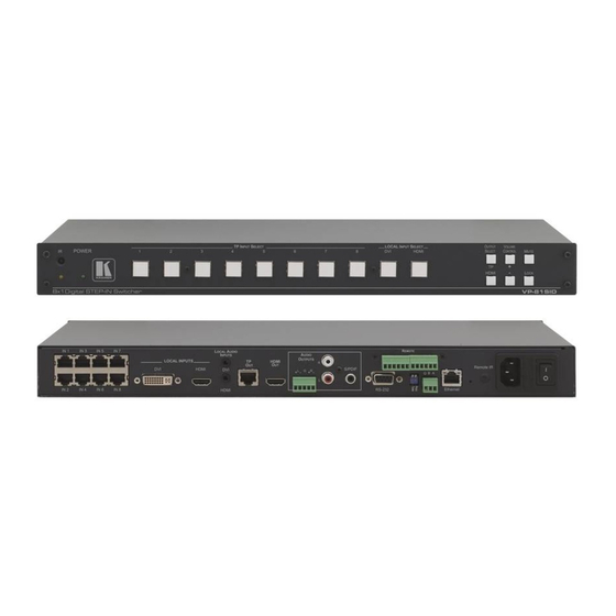
Defining the VP-81SID 8x1 Digital STEP-IN Switcher Figure 1 Table 1 define the front panel of the VP-81SID 8x1 Digital STEP-IN Switcher. Figure 1: VP-81SID 8x1 Digital STEP-IN Switcher Front Panel Table 1: VP-81SID 8x1 Digital STEP-IN Switcher Front Panel Features... -
Page 11: Figure 2: Vp-81Sid 8X1 Digital Step-In Switcher Rear Panel
Defining the VP-81SID 8x1 Digital STEP-IN Switcher Figure 2 Table 2 define the rear panel of the VP-81SID 8x1 Digital STEP-IN Switcher. Figure 2: VP-81SID 8x1 Digital STEP-IN Switcher Rear Panel Table 2: VP-81SID 8x1 Digital STEP-IN Switcher Rear Panel Features... - Page 12 Up = Off, Down = On. Default = On DIP-Switch 2: For the use of Kramer service personnel only RS-485 3-way Terminal Block Connect to RS-485 port on a remote controller or another VP-81SID. Connect: G to Ground, A to A, and B to B (see Section 6.4)
-
Page 13: Using The Ir Transmitter For The Vp-81Sid
Defining the VP-81SID 8x1 Digital STEP-IN Switcher 4.1 Using the IR Transmitter for the VP-81SID You can use the RC-IR3 IR transmitter to operate the VP-81SID via the built-in IR receiver on the front panel or, instead, via an optional external IR receiver . -
Page 14: Installing In A Rack
Installing in a Rack Installing in a Rack This section describes the preparation and installation of the unit in a rack. KRAMER: SIMPLE CREATIVE TECHNOLOGY... -
Page 15: Connecting The Vp-81Sid 8X1 Digital Step-In Switcher
3. Connect an HDMI video source to the LOCAL INPUTS HDMI connector. 1 Be sure that the power is switched off to each device before connecting it to your VP-81SID. After connecting all the devices to your VP-81SID, switch on the power to the VP-81SID, and then switch on the power to each device... -
Page 16: Connecting To A Balanced Audio Acceptor
We therefore recommend that you turn off the VP-81SID and/or the acceptor. Note: When using the PT-572+ in conjunction with the VP-81SID do not connect the 12V power supply to the PT-572+. -
Page 17: Figure 5: Remote Input Selection Switch Wiring
Connected as shown, pressing switch 1 causes input 1 on the VP-81SID to be the active input, and pressing switch 8 causes input 8 to be the active input. Pressing switch A causes the output selection to toggle between the TP and HDMI outputs. -
Page 18: Connecting To The Vp-81Sid Via The Rs-232 Port
To connect to the VP-81SID via RS-232: • Connect the RS-232 9-pin D-sub rear panel port on the VP-81SID unit via a 9-wire straight cable (only pin 2 to pin 2, pin 3 to pin 3, and pin 5 to pin 5 need to be connected) to the RS-232 9-pin D-sub port on your PC 6.4 Connecting to the VP-81SID via the RS-485 Port... -
Page 19: Figure 6: Rs-485 Termination Dip-Switch
DIP-switch positions. Figure 6: RS-485 Termination DIP-switch DIP-switch 1 sets the RS-485 bus termination of the VP-81SID. Only the first and last physical units on the RS-485 bus must be terminated, all others must be unterminated. Moving the DIP-switch up turns the termination off (default), moving the switch down enables the termination. -
Page 20: Connecting To The Vp-81Sid Via The Ethernet Port
IP address. 6.5.1 Connecting Directly to the Ethernet Port You can connect the Ethernet port of the VP-81SID to the Ethernet port on your PC via a crossover cable with RJ-45 connectors. This type of connection is recommended for identification of the factory... -
Page 21: Figure 8: Local Area Connection Properties Window
Connecting the VP-81SID 8x1 Digital STEP-IN Switcher 3. Double-click Network Connections. 4. Right-click, and from the menu select Properties. The Local Area Connection Properties window appears. Figure 8: Local Area Connection Properties Window 5. Select Internet Protocol (TCP/IP) (see Figure 6. -
Page 22: Operating The Vp-81Sid Locally Via The Front Panel Buttons
8. Click OK. 6.5.2 Connecting via a Network Hub, Switch, or Router You can connect the Ethernet port of the VP-81SID to the Ethernet port on a network hub, switch, or router, via a straight through cable with RJ-45 connectors. -
Page 23: Selecting An Output
1. Press the Mute button on the front panel of the VP-81SID. The audio is muted and the button lights. 2. Press the Mute button on the front panel of the VP-81SID a second time. The audio is unmuted and the button no longer lights. -
Page 24: Operating The Vp-81Sid Remotely
Step-In Software for the first time displays a window similar to that shown in Figure The VP-81SID can operate in either the secure mode or the unsecure mode. The factory default mode is unsecure. To change the mode, see Section 14.12.33. -
Page 25: Figure 10: Step-In Software Main Window
Operating the VP-81SID Remotely Figure 10: Step-In Software Main Window Table 4: Main Window Features Feature Function Connect/Disconnect Button Click to connect to or disconnect from the device (see Section 8.1.4) Selected Input Buttons Click to select an input. The selected input button is highlighted... -
Page 26: Figure 11: Typical Input Button
Operating the VP-81SID Remotely Note: When a change is made on the device (for example, a different output is selected), the change is reflected almost immediately in the main window of the Step-in Software, and visa versa. Figure 11 shows a typical input button. -
Page 27: Figure 12: Log In Window
Power cycle the device (Admin only) IR Status Enable or disable the IR control for the device ABOUT Displays the Step-in Software and Kramer company details 8.1.3 Logging in as Admin To log in as admin: 1. Click the Log In button. -
Page 28: Figure 13: Connection Method Window
Operating the VP-81SID Remotely 8.1.4 Connecting to the Device To connect to the device: 1. Click the Connect button. The Connection Method window is displayed as shown in Figure Figure 13: Connection Method Window 2. Select the connection method (via Ethernet over a LAN or a serial connection) by clicking the relevant radio button. -
Page 29: Figure 15: Sid-X1 Input Selection
Operating the VP-81SID Remotely 2. Click on the required output to select. The switch selection is made and the button changes to solid purple. Note: To switch an input to an output, you can click on either an input or an output first, the order is not important. -
Page 30: Figure 16: Changing The Output Volume
Operating the VP-81SID Remotely Figure 16: Changing the Output Volume 2. Drag up to increase or down to decrease the output volume. The volume level changes accordingly. 8.1.8 Muting the Audio Output To mute the audio output: 1. Click the Mute button. -
Page 31: Figure 17: Input Button Properties Window
Operating the VP-81SID Remotely To change an input/output button icon and label: 1. Right-click on the relevant button. The button Input Properties window appears as shown in Figure Figure 17: Input Button Properties Window 2. In the Label text field, enter the required button label. - Page 32 Operating the VP-81SID Remotely 2. Click OK. The device is reset. 8.1.13 Setting the IP Network Parameters To set the IP network parameters you must be logged in as Admin. To set the IP network parameters: 1. Click Unit > Device Details.
-
Page 33: Operating The Vp-81Sid Remotely Via The Embedded Web Pages
Operating the VP-81SID Remotely via the Embedded Web Pages Operating the VP-81SID Remotely via the Embedded Web Pages The embedded Web pages can be used to remotely operate the VP-81SID using a Web browser and an Ethernet connection. Before attempting to connect: •... -
Page 34: Figure 19: The Loading Page
The main switching control Home page is displayed which shows a graphical interpretation of the front panel (see Figure 21). The Web pages let you control the VP-81SID via Ethernet over a LAN. There are four Web pages: KRAMER: SIMPLE CREATIVE TECHNOLOGY... -
Page 35: The Vp-81Sid Panel Page
• The Settings page (see Section 9.5) 9.2 The VP-81SID Panel Page The VP-81SID Panel page lets you perform operational actions, such as, switching inputs/outputs and locking the front panel buttons. Note: Options that are grayed out indicate insufficient user privileges (see Section 9.2.1). -
Page 36: Figure 22: Logging In
Operating the VP-81SID Remotely via the Embedded Web Pages Figure 22: Logging In To log in: 1. From the Login as drop-down list, select either User or Admin. 2. In the Password field enter your password. 3. Click Login. 9.2.2 Selecting an Input To select an input: •... -
Page 37: The Vp-81Sid Audio Volume Page
Figure 25: Locking the Front Panel Buttons 9.3 The VP-81SID Audio Volume Page The VP-81SID Audio Volume page lets you adjust the audio output volume. Figure 26: VP-81SID Audio Volume Page To change the volume of the audio output: •... -
Page 38: The Vp-81Sid Settings Page
9.5 The VP-81SID Settings Page The VP-81SID Settings page lets you configure the device configuration settings, such as, device name and IP settings. Note: Throughout this section options that are not available for an unauthorized user are grayed out. -
Page 39: Wiring The Tp Rj-45 Connectors
Wiring the TP RJ-45 Connectors Wiring the TP RJ-45 Connectors Table 9 Figure 29 define the TP pinout, using a straight pin-to-pin cable with RJ-45 connectors (note that the cable Ground shielding must be connected/soldered to the connector shield). Table 9: TP PINOUT Figure 29: TP Pinout Wiring EIA /TIA 568B... -
Page 40: Technical Specifications
43.7cm x 18.1cm x 4.4cm (17.2” x 7.1” x 1.7”) W, D, H rack-mountable WEIGHT: 2.0kg (4.4lbs) approx. ® ACCESSORIES: Power cord, Windows -based Kramer control software, RC-IR3 Infrared Remote Control transmitter OPTIONS: External remote IR receiver cable ; 15m extension cable REMOTE STEP-IN... -
Page 41: Default Communication Parameters
50000 Maximum UDP Ports: Maximum TCP Ports: Default EDID Each input on the VP-81SID is loaded with an EDID detected on output. If no output EDID is detected, factory default will be used. Monitor Model name....VP-81SID Manufacturer Name = KRM... - Page 42 Refresh Rate = 70 --- Standard Timing 8 --- Horizontal Active Pixel = 1280 Vertical Active Pixel = 960 Image Aspect Ratio = 4:3 Refresh Rate = 60 *** Detail Timings/Monitor Descriptors *** --- BK0.Detail Timing1 --- KRAMER: SIMPLE CREATIVE TECHNOLOGY...
- Page 43 Default EDID Pixel Clock(MHz) = 74.250 H/V Active = 1280 / 720 H/V Blanking = 370 / 30 H/V Sync Offset = 110 / 5 H/V Sync Width = 40 / 5 H/V Image Size(mm) = 519 / 324 Scanning Mode = Non interlace Stereo = Normal display no stereo Sync Type = Digital Seperate H/V Sync Polarity = Positve/Positive...
- Page 44 58 //DF 28 25 00 E8 12 11 00 00 //E7 98 01 1D 00 BC 52 D0 1E //EF 20 B8 28 55 40 E8 12 11 //F7 00 00 1E 00 00 00 00 4F //FF KRAMER: SIMPLE CREATIVE TECHNOLOGY...
-
Page 45: Protocol 3000 Syntax
Protocol 3000 Syntax Protocol 3000 Syntax The Kramer Protocol 3000 lets you control the device from any standard terminal software (for example, the Windows® HyperTerminal Application). 14.1 Host Message Format Start Address (optional) Body Delimiter device_id@ Message 14.2 Simple Command Command string with only one command without addressing. -
Page 46: Command Terms
You can directly enter all commands using a terminal with ASCII communications software, such as HyperTerminal, Hercules, etc. Connect the terminal to the serial, Ethernet, or USB port on the Kramer device. To enter , press the Enter key. is also sent but is ignored by command parser). -
Page 47: Bi-Directional Definition
Commands in the string do not execute until the closing character is entered. A separate response is sent for every command in the chain. 14.11 Maximum String Length 64 characters 14.12 Backward Support The VP-81SID supports the commands listed in Table Table 12: Communication Commands Command Parameters Description Protocol handshaking... - Page 48 PRIO 1/0 (1=mute on,0=mute Set audio mute for device MUTE off) Enable/Disable IR driver IREN input, sid-x1 input Switch inputs on SID-X1 via VP-81SID (as VID-TYPE described in Section 8.1.6) GET Commands Get current input-to-output routing setting AV?/V?/VID? Get Volume...
- Page 49 Protocol 3000 Syntax 14.12.2 MODEL? Command Name Short Cmd Command Type Permission MODEL? Common-mandatory End User Read device model Syntax #MODEL?␍ Response ~nn@MODEL␠model_name␍␊ Parameters model_name – String of printable ASCII chars (up to 19 chars). Notes 14.12.3 VERSION? Command Name Short Cmd Command Type Permission...
- Page 50 Reset device serial number Syntax #SN?␍ Response ~nn@SN␠serial_number␍␊ Parameters serial_number – 11 decimal digits. Assign by Kramer factory. Notes For new products with 14 digits serial we kept only the last 11. 14.12.5 NAME? Command Name Short Cmd Command Type...
- Page 51 Protocol 3000 Syntax 14.12.6 MACH-NUM Command Name Short Cmd Command Type Permission MACH-NUM Common End User Set Machine number Syntax #MACH-NUM␠machine_number␍ Response ~nn@MACH-NUM␠machine_number OK␍␊ Parameters machine_number – New machine number to device Notes Some devices will not get the new machine number until restart the device. Some devices can change machine number only from dip-switches 14.12.7 BUILD-DATE? Command Name...
- Page 52 Get commands list or help for specific command Syntax 2 options: 1. #HELP␍ 2. #HELP␠command_name␍ Response 1. Multi-line: ~nn@Device available protocol 3000 commands:␍␊command,␠command…␍␊To get help for command use : HELP (COMMAND_NAME)␍␊ 2. Multi-line: ~nn@HELP␠command:␍␊description␍␊USAGE:usage ␍␊ Parameters Notes KRAMER: SIMPLE CREATIVE TECHNOLOGY...
- Page 53 Protocol 3000 Syntax 14.12.10 RESET Command Name Short Cmd Command Type Permission RESET Common-mandatory Administrator Reset device Syntax #RESET␍ Response ~nn@RESET␠OK␍␊ Parameters Notes If device connected by USB, it’s recommend to disconnect the connection immediately after operating this command, to eliminate port locking because USB bug in windows (if port was locked anyway, disconnect and reconnect the cable and then try to open port again).
- Page 54 – ‘0’ or ‘off’ to unlock front panel buttons. ‘1’ or ‘on’ to lock front panel buttons. device_id – For K-Net controllers, select the buttons panel to lock. Locking is allowed only from the master. Notes KRAMER: SIMPLE CREATIVE TECHNOLOGY...
- Page 55 Protocol 3000 Syntax 14.12.14 LOCK-FP? Command Name Short Cmd Command Type Permission LOCK-FP? Common End User Get lock state of front panel Syntax Option 1: #LOCK-FP?␍ Option 2: #LOCK-FP?␠device_id␍ Response Option 1: ~nn@LOCK-FP␠lock_mode␍␊ Option 2: ~01@LOCK-FP␠device_id, lock_mode␍␊ Parameters lock_mode – ‘OFF’ for unlocked front panel. ‘ON’ for locked front panel. device_id –...
- Page 56 In - input number or '0' to disconnect output '>' = Connection character between in and out parameters out = Output number or '*' for all outputs Notes Out = 1 (TP output) Out = 2 (HDMI output) KRAMER: SIMPLE CREATIVE TECHNOLOGY...
- Page 57 Protocol 3000 Syntax 14.12.18 VID Command Name Short Cmd Command Type Permission Switch End User Switch Video Syntax #VID␠in>out, in>out,…␍ Response ~nn@VID␠in>out ␍␊ ~nn@VID␠in>out ␍␊ … Parameters In - input number or '0' to disconnect output '>' = Connection character between in and out parameters out = Output number or '*' for all outputs Notes When AFV switching mode is active, this command also switches Audio and the unit replies with command ~AV.
- Page 58 Response ~nn@VOLUME␠ out_ channel, volume ␍␊ Parameters out_channel = Output # volume = Audio parameter in Kramer units, minus sign precedes negative values. ++ increase current value, -- decrease current value Notes For set / get “input” level or audio level in other amplifier stage use command #AUD-LVL / #AUD-LVL? – set / get audio level in specific amplifier stage 14.12.21 VOLUME?
- Page 59 Protocol 3000 Syntax 14.12.22 PRIO Command Name Short Cmd Command Type Permission PRIO Device specific Administrator Syntax Response PRIO INPUT , PRIORITY PRIO INPUT , PRIORITY OK Description Notes Set input Priority INPUT – 1…10 PRIORITY - 1..10 14.12.23 MUTE Command Name Short Cmd Command Type...
- Page 60 VID-TYPE INPUT , SID-X1 INPUT VID-TYPE INPUT , INPUT TYPE , IS_X1_INPUT Description Notes Switch SID-X1 inputs remotely via VP-81SID INPUT - input No. of switcher, where HDMI=0, DP=1, DVI=2, VGA=3 SID-X1 INPUT – input No. of SID-X1 to switch to INPUT_TYPE –...
- Page 61 Protocol 3000 Syntax 14.12.27 IREN? Command Name Short Cmd Command Type Permission IREN? Common End User Syntax Response IREN? IREN 1/0 Description Notes Get IR control current status 1/0= On OR Off 14.12.28 VID-RES? Command Name Short Cmd Command Type Permission VID-RES? Device specific...
- Page 62 ~nn@GEDID␠eeprom_id, size␍␊ Edid_data␍␊ ~nn@GEDID␠eeprom_id ␠OK␍␊ Parameters eeprom_id – EEPROM to get the EDID from size – Device send this parameter in response. Size of EDID that will print. edid_data – EDID data as stream of bytes. Notes KRAMER: SIMPLE CREATIVE TECHNOLOGY...
- Page 63 Protocol 3000 Syntax 14.12.32 FPGA-VER? Command Name Short Cmd Command Type Permission FPGA-VER? <?> Device specific End User Syntax Response FPGA-VER? ID FPGA-VER? FPGA version number , ID Description Notes Request FPGA version by FPGA ID (optional) 14.12.33 SECUR Command Name Short Cmd Command Type Permission...
- Page 64 Command Type Permission SECUR? Security Administrator Get current security state Syntax #SECUR?␍ Response ~nn@SECUR␠security_mode␍␊ Parameters security_mode –ON if security enabled. OFF if security disabled. Notes Permissions system work only if security was enabled (by “SECUR” command) KRAMER: SIMPLE CREATIVE TECHNOLOGY...
- Page 66 For the latest information on our products and a list of Kramer distributors visit www.kramerelectronics.com where updates to this user manual may be found. We welcome your questions, comments and feedback. Safety Warning: Disconnect the unit from the power supply before opening/servicing.
Need help?
Do you have a question about the VP-81SID and is the answer not in the manual?
Questions and answers