Table of Contents
Advertisement
Quick Links
Advertisement
Table of Contents

Related Manuals for Invacare top end terminator series


Summary of Contents for Invacare top end terminator series
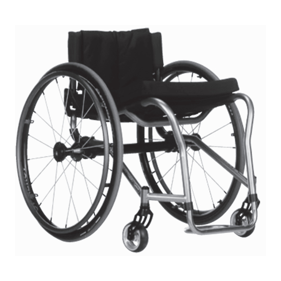
- Page 1 Top End® Terminator™Series Terminator Titanium, Terminator with Heavy Duty Option, Terminator Everyday EN Wheelchairs User Manual This manual MUST be given to the user of the product. BEFORE using this product, read this manual and save for future reference.
- Page 2 All rights reserved. Republication, duplication or modification in whole or in part is prohibited without prior written permission from Invacare. Trademarks are identified by ™and ®. All trademarks are owned by or licensed to Invacare Corporation or its subsidiaries unless otherwise noted.
-
Page 3: Table Of Contents
Back Height Adjustment (Adjustable Back Contents Only) ........31 Adjusting the T-Arms . - Page 4 5.14 Replacing Adjustable Tension Seat Upholstery ..59 5.15 Replacing Screw-On Seat Upholstery... . . 60 5.16 Replacing/Adjusting Optional Adjustable Angle Footrest ....... . . 60 5.17 Installing/Removing/Adjusting Swivel Anti-Tip.
-
Page 5: General
1.4 Dealer/Technician Information CAUTION! – Caution indicates a potentially hazardous situation The term “qualified technician” in this manual refers to an Invacare which, if not avoided, may result in property damage qualified technician. or minor injury or both. -
Page 6: Safety
WARNING! ACCESSORIES – Invacare products are specifically designed and manufactured for use in conjunction with Invacare accessories. Accessories designed by other manufacturers have not been tested by Invacare and are not recommended for use with Invacare products. 1171801-A... -
Page 7: Stability Warning
Safety 2.2 Stability Warning When changes to the left hand column occur, follow across the chart and refer to the procedure that is checked to WARNING! maintain the proper stability, safety and handling of the – The position of the footrest, camber tube, back angle, wheelchair. -
Page 8: Operating Information
(you may order with or without the – DO NOT shift your weight or sitting position toward anti-tippers), Invacare strongly recommends ordering the direction you are reaching as the wheelchair may the anti-tippers as an additional safeguard for the tip over. - Page 9 – The seat positioning strap is a positioning belt only. It Weight Training is not designed for use as a safety device withstanding – Invacare DOES NOT recommend the use of its high stress loads such as auto or aircraft safety belts. wheelchairs as a weight training apparatus. Invacare...
-
Page 10: Weight Capacity
Keep your back straight and bend your Weight Capacity knees whenever tilting the wheelchair or traversing curbs, or other – Invacare's Terminator Titanium wheelchairs have a impediments. weight capacity of 250 lbs (113.4 kg). – Terminator Titanium wheelchairs with the heavy duty WARNING! option have a weight capacity of 400 lbs (181.4 kg). -
Page 11: Weight Distribution
Safety 2.7 Weight Distribution WARNING! – The position of the footrest, camber tube, back angle, the tautness of the back upholstery as well as the user's condition are directly related to the wheelchair's stability. Any change to one or any combination of the five may cause the wheelchair to decrease in stability. -
Page 12: Reaching, Leaning And Bending
® Top End Terminator™Series 2.8 Reaching, Leaning and Bending Forward or Sideways Forward or Sideways Position the front casters so that they are extended as far forward as possible and engage wheel locks. WARNING! – DO NOT attempt to reach objects if you have to move forward in the seat. -
Page 13: Tipping
Do not let the wheelchair drop the last few WARNING! inches to the ground. This could result in injury to the occupant. – Invacare does not recommend that sport wheelchairs Turn the anti-tippers so the wheels are facing down. be used where traversing curbs present an obstacle. -
Page 14: Stairways
® Top End Terminator™Series 2.10 Stairways 2.11 Transferring To and From Other Seats Follow this procedure for moving the wheelchair between floors WARNING! when an elevator is NOT available: – Before attempting to transfer in or out of the If equipped, turn the anti-tippers up. Refer to 4.17 wheelchair, every precaution should be taken to Adjusting/Replacing Footrest, page 46 . -
Page 15: Safety Inspection Checklist
Safety Inspect/Adjust Initially Ensure wheelchair rolls straight (no excessive drag/pull to one side). Ensure wheel locks Do not interfere with tires when rolling. Ensure pivot points are free of wear and looseness. Ensure wheel locks are easy to engage. Inspect seat and back upholstery for rips or sagging. Inspect upholstery fastening flaps to ensure they securely latch. - Page 16 ® Top End Terminator™Series If pneumatic tires check for proper inflation. CAUTION! Ensure casters are free of debris. – As with any vehicle, the wheels and tires should be Check that all labels are present and legible. Replace if necessary. checked periodically for cracks, flat spots and wear, and should be replaced if damaged.
-
Page 17: Overview
Overview Component Identification 3 Overview Terminator Titanium 3.1 Label Locations and Component Identification Serial number label is located underneath the seat. The weight capacity label is on the camber tube. 1171801-A... -
Page 18: Typical Product Parameters
® Top End Terminator™Series 3.2 Typical Product Parameters Top End Terminator Titanium FRAME: Grade 9 Titanium .035, heavy duty Grade 9 Titanium .051 wall thickness SEAT WIDTH: 12-18 inches (30.48 - 45.72 cm) - Outside to Outside of SEAT FRAME in 1-inch (2.54 cm) increments SEAT DEPTH: 14 to 18 (35.56 - 45.72 cm) inches... - Page 19 Overview Top End Terminator Titanium REAR AXLE: Adjustable Axle Position, Quick (Standard) or Quad-Release REAR WHEEL CAMBER — CAMBER TUBE 2000: 0°, 3°, 6°, 9° REAR WHEEL CAMBER — ADJUSTABLE CAMBER 0°, 3°, 6°, 9°, 12° SYSTEM: REAR WHEELS Sun High performance (Standard), Spinergy SPOX, Spinergy LX 22–INCH (21.22 ZOLL) 24–INCH (23.14 ZOLL) (STANDARD) 25–INCH (24.1 ZOLL)
- Page 20 ® Top End Terminator™Series SHIPPING WEIGHT: 30 lbs (13.6 kg) WEIGHT CAPACITY: 250 lbs (113.4 kg)/400 lbs (181.44 kg) with Heavy Duty Option Top End Terminator Everyday FRAME: 6061 T6 Aluminum .083, Heavy Duty Option 4031 Chrome-moly steel. SEAT WIDTH: 12-18 inches (30.48 - 45.72 cm) - Outside to Outside of SEAT FRAME in 1-inch (2.54 cm) increments SEAT DEPTH:...
- Page 21 Overview Top End Terminator Everyday SIDE-WHEEL CLEARANCE: Adjustable 1/2 to 1-1/2-inches (1.27 - 3.81 cm) REAR AXLE: Adjustable Axle Position, Quick (Standard) or Quad-Release REAR WHEEL CAMBER — CAMBER TUBE: 0°, 3°, 6°, 9° REAR WHEEL CAMBER — ADJUSTABLE CAMBER 0°, 3°, 6°, 9°, 12°...
- Page 22 ® Top End Terminator™Series SHIPPING WEIGHT: 30 lbs (13.6 kg) WEIGHT CAPACITY: 250 lbs (113.4 kg)/350 lbs (158.75 kg) with Heavy Duty Option – 15 x 15-inch (38.1cm) seat, rear wheels and minimal options are included in the weight. – *Refer to 3.3 Tire Pressure Conversion, page 23. –...
-
Page 23: Tire Pressure Conversion
Overview 3.3 Tire Pressure Conversion If equipped with high pressure tires, a Presta valve adaptor will be needed to inflate the tires to the recommended pressures below. PSI rating is printed on the side of the tire. Conversion formula: 1 psi = 6.895 kPa (approx. 7 kPa). KILSOPASCALS KILOPASCALS 1171801-A... -
Page 24: Operation
® Top End Terminator™Series 4 Operation 4.1 Unfolding/Folding the Back WARNING! – After any adjustments, repair or service and before use, make sure all attaching hardware is tightened securely. Otherwise injury or damage may occur. – ALWAYS perform these procedures in the presence of an assistant. -
Page 25: Back Angle Adjustment
Operation 4.2 Back Angle Adjustment Note the indent on the adjustment square. When the adjustment square is positioned in the back angle plate, WARNING! the number that is located directly next to the indent will – If the adjustment square is installed into the back angle be back angle relative to true vertical. - Page 26 ® Top End Terminator™Series Position the adjustment square B in the back plate C with the DETAIL “B” indent located underneath the desired back angle. Secure the adjustment square B to the back angle plate C with the mounting screw A. Tighten securely. Repeat STEPS 2-6 for remaining back cane C (Detail “A”).
- Page 27 Operation ADJUSTMENT SQUARE POSITION DESIRED SEAT ANGLE NUMERICAL GRAPHICAL –8° -4° OPTION 1 OPTION 2 0° 1171801-A...
- Page 28 ® Top End Terminator™Series ADJUSTMENT SQUARE POSITION DESIRED SEAT ANGLE NUMERICAL GRAPHICAL +4° +8° 1171801-A...
-
Page 29: Adjustable Tension Back Upholstery
Operation 4.3 Adjustable Tension Back Upholstery Replacing Adjustable Tension Back Upholstery WARNING! – The position of the footrest, seat angle, back angle, seating system/upholstery, caster size and position, rear wheel size and position, use of anti-tippers, as well as the user condition directly relate to the stability of the wheelchair. - Page 30 ® Top End Terminator™Series Remove the back height adjustment screws A that secure the WARNING! back posts B to the back uprights C. – After the adjustable tension back upholstery Slide the back posts B out of the back uprights C. has been positioned to the end-users individual Remove the two screws and washers D that secure the existing needs, the fastening straps MUST be securely...
-
Page 31: Back Height Adjustment (Adjustable Back Only)
Operation 4.4 Back Height Adjustment (Adjustable Back There is a 1-inch (2.54 cm) adjustment pin on the back post insert tube A. To raise back to maximum height, first make Only) adjustment to the back post inserts A. Observe the tautness of the back upholstery for The fastening flap with logo is for the left back post B. -
Page 32: Adjusting The T-Arms
® Top End Terminator™Series 4.5 Adjusting the T-Arms Loosen - Loosening the set screws D on the outside T-arm post C will make it easier to move the inside T-arm A post up and Adjusting T-Arm Height down. Lock the T-arm by flipping the T-arm release lever B towards the front of the wheelchair. -
Page 33: Adjusting T-Arm Sockets
Operation Adjusting T-Arm Depth Reattach the arm pad A to the arm tube D with the two mounting screws C. Tighten securely. Repeat for the opposite side, if necessary. 4.6 Adjusting T-Arm Sockets Remove the two mounting screws C that secure the arm pad A to the arm tube D. -
Page 34: Adjusting Quick-Release Axles
® Top End Terminator™Series 4.7 Adjusting Quick-Release Axles Slide the T-arm A into the T-arm socket until the locking lever F is in the slot B in the T-arm socket and an audible "click" is Remove rear wheel and quick-release axle B from the heard. -
Page 35: Adjusting Quad-Release Handles
Operation 4.8 Adjusting Quad-Release Handles 4.9 Removing Play from Rear Wheels With the rear wheel and quad-release axle A still mounted on the wheelchair, tighten the length adjusting screw C until there is no in and out movement of the quad-release axle A and rear wheel. Refer to diagram in 4.8 Adjusting Quad-Release Handles, page 35 4.10 Opening/Closing Camber Clamps... - Page 36 ® Top End Terminator™Series • Suspension Camber Clamps - Loosen, but do not remove Side View of Standard Camber Clamp the hex screw D on the bottom rear of the camber clamp Perform one of the following to close a camber clamp: •...
-
Page 37: Adjusting Rear Wheel Camber
Operation 4.11 Adjusting Rear Wheel Camber Reinstall the rear wheel into the camber insert B. Camber Tube with Single Camber WARNING! The axle tube must be replaced to change the camber. Refer to 5.11 – NEVER position the camber inserts in the axle Replacing Axle Tube, page 55 . - Page 38 ® Top End Terminator™Series • Determine difference between two measurements. If difference If the back centerline measurement of the rear wheels is LARGER D than the front centerline measurement of the between the two measurements is greater than 1/2-inch (1.27 cm) (0 + 1/4-inch (0.63 cm) for maximum rollability), one of two rear wheels, a TOE-IN condition E exists.
-
Page 39: Adjusting Toe In/Toe Out
Operation 4.13 Adjusting Toe In/Toe Out Camber Tube with Single Camber Open the camber clamps. Slowly rotate the camber tube in either direction until the rear wheels are approximately in a straight line. Close the camber clamps. Measure the distance between the center lines at the rear and front of the rear wheels at approximately 12 inches (30.48 cm) from the ground/floor. - Page 40 ® Top End Terminator™Series – When positioning the other adjustment ring B, rotate Stop-In position for one camber, Stop-Not touching camber the ring until the stop C is at the bottom of the slot touching camber clamp. clamp. in the camber clamp A. The right and left stops C MUST be positioned opposite to each other or Fine Adjustment on page will not work correctly.
-
Page 41: Adjusting Wheelbase Length (Center Of Gravity)
Operation 4.14 Adjusting Wheelbase Length (Center of • Suspension - Loosen, but do not remove the two hex screws A that secure each of the top clamps B to the Gravity) wheelchair frame C. WARNING! – ALWAYS perform this procedure in the presence of an assistant. -
Page 42: Adjusting Wheelbase Width
® Top End Terminator™Series 4.15 Adjusting Wheelbase Width • Suspension - Securely tighten the two hex screws A that secure one of the top clamps B to the wheelchair frame C. – Perform this procedure on one side of the wheelchair –... -
Page 43: Adjusting The Axle Tube
Operation – Axle bolt C removed from axle tube D for clarity. – Before using the wheelchair, make sure both It is not necessary to remove the axle bolt C for camber inserts B are set at the same indexing mark C. - Page 44 ® Top End Terminator™Series Camber Tube with Single Camber Securely tighten set screw on left toe adjustment ring B. Measure the distance between the center lines at the rear and front of the rear wheels at approximately 12 inches (30.48 cm) from the ground/floor.
- Page 45 Operation Lower Degree of Camber Higher Degree of Camber 1171801-A...
-
Page 46: Adjusting/Replacing Footrest
– Anti-tippers must be attached at all times. Inasmuch as Install new footrest B. the anti-tippers are an option on this wheelchair (you may order it with or without the anti-tippers), Invacare strongly recommends ordering the anti-tippers as an additional safeguard for the wheelchair user. - Page 47 Operation Replacing Anti-Tipper Press in the release button D on the anti-tipper bar E and install the anti-tipper wheels onto the new anti-tipper bar E. Press in the release button D that secures the existing anti-tipper Repeat STEPS 1-3 for the opposite anti-tipper C. C to the anti-tipper socket D and remove the anti-tipper C Measure the distance between the bottom of the anti-tipper from the anti-tipper socket.
-
Page 48: Service
® Top End Terminator™Series 5.2 Installing the Swingaway Padded Armrest 5 Service Socket 5.1 Removing/Installing Foldover Back Upholstery WARNING! Removing – After any adjustments, repair or service and before use, make sure all attaching hardware is tightened securely - otherwise injury or damage may occur. –... - Page 49 Service Remove or fold down the back. Refer to 4.1 Unfolding/Folding the Back, page 24. Insert mounting bolt A into the mounting hole B at the desired height on the swingaway padded armrest socket C and secure with the locknut. Install the swingaway padded armrest D.
-
Page 50: Installing/Removing/Adjusting The Swingaway Padded Armrest
® Top End Terminator™Series 5.3 Installing/Removing/Adjusting the Swingaway 5.4 Installing the T-Arm Sockets Padded Armrest Installing the Swingaway Padded Armrest Secure mounting bolt A and locknut B in desired mounting hole C. Tighten securely. Insert swing away padded armrest D into armrest socket E so that notch fits around mounting bolt A. -
Page 51: Installing/Removing T-Arms
Service 5.5 Installing/Removing T-Arms Removing T-Arms Installing T-Arms Press in on the locking lever D and lift the T-arm B straight up and out of the T-arm socket C. If the T-Arm B does not slide in the T-Arm socket C as desired, adjust the T-Arm socket. -
Page 52: Removing/Installing Rear Wheels
® Top End Terminator™Series Perform one of the following: WARNING! – DO NOT overtighten locknut that secures locking • Quick-Release - Push in the tip of the quick-release axle A lever to bottom bracket. Overtightening this and pull axle and wheel away from the wheelchair B. locknut will prevent locking lever from operating •... -
Page 53: Handrim Replacement
Service 5.8 Handrim Replacement WARNING! – DO NOT inflate tire until it is completely assembled - otherwise, injury or damage may occur. – Recommended tire pressure is listed on the side wall of the tire. DO NOT overinflate the tires. Failure to follow these suggestions may cause the tire to explode and cause bodily harm. -
Page 54: Repairing/Replacing Rear Wheel Tire/Tube
Replacing/Adjusting Casters, page 57 ONLY after Insert new quad-release axle through rear wheel hub B. contacting Invacare. Anti-tipper height (if applicable) Slide locking collar C onto quad-release axle until it is snug must also be adjusted to maintain 1-1/2 to 2-inch against rear wheel and tighten securely with allen screw D. -
Page 55: Replacing Axle Tube
Service 5.11 Replacing Axle Tube Camber Tube with Single Camber Rear of Wheelchair – The camber bar is always mounted to the bottom of the wheelchair frame. – There is no need to remove the two camber clamps C when replacing the axle tube B. Adjustable Camber System Rear of Wheelchair Front of Wheelchair... - Page 56 ® Top End Terminator™Series 13. Adjustable Camber System Only - Slide the indexing ring F on – Adjustable Camber System Only - Make sure the the camber insert A until it is flush with the camber clamp C. notches in the axle tube B are towards the rear of the wheelchair and the slots in the axle tube B –...
-
Page 57: Replacing/Adjusting Casters
Perform one of the following: wheelchair. – Contact Invacare at the telephone numbers on the • Non-Suspension Fork - Install the new caster C, bolt A, back of this manual before performing this procedure. - Page 58 ® Top End Terminator™Series Front Rear Wheel Lock Adjustment Measure the distance between the wheel lock shoe D and the rear wheel E. Slide the wheel lock B along the wheelchair until the measurement is between 5/32 and 5/16-inches (0.4 and Loosen the locknuts and hex/allen screws A that secure the 0.8 cm) F.
-
Page 59: Replacing Adjustable Tension Seat Upholstery
Service 5.14 Replacing Adjustable Tension Seat Slip front adjuster strap A through corresponding anchor loop E and adjust the seat upholstery B to desired tension. Secure Upholstery the adjustment straps A. WARNING! Place the wheelchair onto its two rear wheels and back post. –... -
Page 60: Replacing Screw-On Seat Upholstery
® Top End Terminator™Series 5.15 Replacing Screw-On Seat Upholstery 5.16 Replacing/Adjusting Optional Adjustable Angle Footrest WARNING! A footrest for short leg lengths is available as an option. It – After any adjustments, repair or service and before has an adjustable footplate with 2 inch spacers and longer use, make sure all attaching hardware is tightened mounting screws that attach the footrest to the footrest securely. -
Page 61: Installing/Removing/Adjusting Swivel Anti-Tip
Service Adjusting Footplate Angle Loosen, but do not remove the two mounting screws E and locknuts (not shown) that secure the footplate D to the footrest tubes C. Position the footplate D to the necessary angle to accommodate the user. Tighten the two mounting screws E and locknuts. -
Page 62: Elastomers And Suspension
® Top End Terminator™Series 5.18 Elastomers and Suspension WARNING! – After any adjustments, repair or service and before use, make sure all attaching hardware is tightened securely. Otherwise injury or damage may occur. – The performance of the wheelchair will be affected if elastomers are not the same on both sides of the wheelchair. - Page 63 Service Position the new elastomer E between the recess F in the axle Using two allen wrenches, turn in opposite directions and bracket G and the recess F in the suspension base H. remove one mounting screw A from fork B. Compress and hold the elastomer E between the axle bracket –...
-
Page 64: Troubleshooting
® Top End Terminator™Series 6 Troubleshooting 6.1 Troubleshooting Veers Right Veers Left Sluggish Turn or Casters Flutter Squeaks and Looseness Solutions Performance Rattles in Chair Check tires for correct and equal pressure. Check for loose stem nuts. Check spokes and nipples. Check that both casters contact the ground at the same time. -
Page 65: Maintenance
The wheels, casters and tires should be checked periodically for returning product. cracks and wear, and should be replaced if damaged. Contact a qualified technician or Invacare customer support at the Suggested Maintenance Procedures telephone numbers on the back of this manual. -
Page 66: Options
® Top End Terminator™Series 8 Options If sideguard will not pivot freely, bolt through sideguard clamp D and sideguard C is too tight. To correct, loosen bolt. 8.1 Options If sideguard rattles, bolt through sideguard clamp D and Installing/Adjusting the Fold-in Sideguards sideguard C is too loose. - Page 67 Options Loosen two mounting screws A in side guard B. DETAIL “B” Remove side guard clamp C from back posts. Adjusting the Fold-In Sideguards Height Installing the Bolt-on Push Handles Lift sideguard to a level position (Detail “A”). Remove bolt from sideguard clamp D and sideguard C. Adjust sideguard C to desired height.
- Page 68 ® Top End Terminator™Series Using the mounting screw attach the bolt-on push handles to the back canes. Installing/Adjusting the Adjustable Push Handles To Install: Loose the two mounting screws A in the push handle clamp B. Attach adjustable push handle C to back cane by inserting the back cane into the push handle clamp B.
-
Page 69: Warranty
Invacare warrants the frames when purchased new and unused to be free from defects in materials and workmanship for a period of five (5) years from the date of purchase from Invacare or a dealer, with a copy of the seller’s invoice required for coverage under this warranty. - Page 70 ANY COMPONENT WITHOUT THE SPECIFIC CONSENT OF INVACARE, OR TO A PRODUCT DAMAGED BY CIRCUMSTANCES BEYOND INVACARE’S CONTROL, AND SUCH EVALUATION WILL BE SOLELY DETERMINED BY INVACARE. THE WARRANTY SHALL NOT APPLY TO NORMAL WEAR AND TEAR OR FAILURE TO ADHERE TO THE PRODUCT INSTRUCTIONS.
-
Page 71: European, Australian, And New Zealand Limited Warranty Information And Customer Service
Asia Ireland: 1 Lenton Place, P.O. Box 5002, North Rocks, NSW 2151 Invacare Ireland Ltd, Unit 5 Seatown Business Campus, Seatown Road, Swords, County Dublin - Ireland Tel: 61 2 889 5330 Fax: 61 2 8839 5331 Tel: (353) 1 810 7084, Fax: (353) 1 810 7085 asiasales@invacare.com www.invacare.com... - Page 72 Invacare Corporation www.invacare.com and www.topendchair.com Manufactured by: One Invacare Way Top End Sports and Recreation Products Elyria, Ohio USA 4501 63rd Circle North 44036–2125 Pinellas Park, Florida (727) 522–8677 (800) 333–6900 (800) 532–8677 EU Representative: Küschall AG, Benkenstrasse 260, CH-4108...
Need help?
Do you have a question about the top end terminator series and is the answer not in the manual?
Questions and answers