Fluke 110 User Manual
True rms multimeters
Hide thumbs
Also See for 110:
- User manual ,
- Calibration information manual (26 pages) ,
- User manual (22 pages)

Related Manuals for Fluke 110


Summary of Contents for Fluke 110
- Page 1 ® Models 110, 111 & 112 True RMS Multimeters Users Manual November 2000 (English), Rev.2, 3/04 © 2000-2004 Fluke Corporation. All rights reserved. Printed in China...
- Page 2 Fluke authorized resellers shall extend this warranty on new and unused products to end-user customers only but have no authority to extend a greater or differ- ent warranty on behalf of Fluke. Warranty support is available only if product is purchased through a Fluke authorized sales outlet or Buyer has paid the applica- ble international price.
-
Page 3: Table Of Contents
Table of Contents Title Page Read Before Using the Meter: Warnings and Precautions ............ ii Contacting Fluke ........................1 "Warning" and "Caution" Statements..................1 Unsafe Voltage........................1 Test Lead Alert ........................1 Battery Saver ("Sleep Mode")....................2 Terminals ..........................2 Rotary Switch Positions...................... -
Page 4: Read Before Using The Meter: Warnings And Precautions
Models 110, 111 & 112 Users Manual Read Before Using the Meter: Warnings and Precautions To avoid possible electric shock or personal injury, follow these guidelines: Use the Meter only as specified in this manual or the protection provided by the Meter might be impaired. -
Page 5: Contacting Fluke
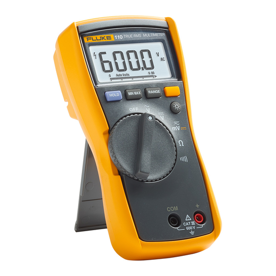
Models 110, 111 & 112 True RMS Multimeters "Warning" and "Caution" Statements The Fluke Model 110, Model 111, and Model 112 are battery- powered, true-RMS multimeters (hereafter "the Meter") with a A "WWarning" statement identifies hazardous conditions and 6000-count display and a bar graph. This manual applies to all actions that could cause bodily harm or death. -
Page 6: Battery Saver ("Sleep Mode")
Models 110, 111 & 112 Users Manual Battery Saver ("Sleep Mode") Rotary Switch Positions The Meter automatically enters "Sleep mode" and blanks the Switch Position Measurement Function display if there is no function change or button press for 20 AC voltage from 300 mV to 600 V. -
Page 7: Display
True RMS Multimeters Display Display Symbol Meaning Measurement units. n F mVA Direct current, alternating current. DC AC Replace battery immediately. All possible segments of the range 610000 mV annunciator. Analog display. (Bar graph) The Meter selects the range with the Auto Range best resolution. -
Page 8: Min Max Avg Recording Mode
Models 110, 111 & 112 Users Manual MIN MAX AVG Recording Mode Display HOLD The MIN MAX AVG recording mode captures the minimum and WWarning maximum input values, and calculates a running average of all To avoid electric shock, when Display HOLD is readings. -
Page 9: Manual Ranging And Auto Ranging
True RMS Multimeters Manual Ranging and Auto Ranging Manual Ranging and Auto Ranging Power-Up Options The Meter has both Manual Range and Auto Range modes. To select a Power-Up Option, hold down the button indicated for at least 1 second while turning the Meter on. ⇒... -
Page 10: Making Basic Measurements
Models 110, 111 & 112 Users Manual Making Basic Measurements Measuring AC and DC Voltage The figures on the following pages show how to make basic measurements. Volts AC Volts DC When connecting the test leads to the circuit or device, connect the common (COM) test lead before connecting the live lead;... -
Page 11: Measuring Resistance
True RMS Multimeters Making Basic Measurements Note Measuring Resistance The 3.00 A AC minimum specified reading is calculated by the Meter as 5% of 60 A. However for safety and compactness, the current shunt in the Meter is specified for 10 A continuous, 20 A overload for up to 30 seconds. -
Page 12: Testing For Continuity
Models 110, 111 & 112 Users Manual Testing for Continuity Testing Diodes Good Diode Good Diode Single Beep aej06f.eps Reverse Bias Forward Bias Note Bad Diode Bad Diode The continuity function works best as a fast, convenient method to check for opens and shorts. For maximum accuracy in making resistance measurements, use the Meter’s resistance (e) function. -
Page 13: Measuring Ac Or Dc Current (Models 111 And 112)
True RMS Multimeters Making Basic Measurements Measuring AC or DC Current (Models 111 and 112) Measuring Frequency WWarning WWarning To avoid personal injury or damage to the Meter: To avoid electrical shock, disregard the bar graph for frequencies > 500 Hz. If the frequency of the measured Never attempt to make an in-circuit current measure- signal is >... -
Page 14: Using The Bar Graph
Models 110, 111 & 112 Users Manual Using the Bar Graph The bar graph is like the needle on an analog meter. It has an overload indicator (>) to the right and a polarity indicator ( ) to the left. -
Page 15: Testing The Fuse (Models 111 And 112)
Minimum Interrupt Rating 17000 A. Replace the battery as soon as the low battery Use only Fluke Part Number 803293. indicator ( ) appears to avoid false readings. Battery, 9 V Alkaline, NEDA 1604A / IEC 6LR61... -
Page 16: Specifications
Models 110, 111 & 112 Users Manual Specifications Accuracy is specified for 1 year after calibration, at operating temperatures of 18 C to 28 C, with relative humidity at 0 % to 95 %. The accuracy specifications take the form of:... - Page 17 True RMS Multimeters Specifications Accuracy ± ( [ % of Reading ] + [ Counts ] ) Function Range Resolution Model 110 Model 111 Model 112 1,2,3 AC Volts -- True RMS 6000 mV 1 mV (50 Hz to 500 Hz) 6.000 V...
- Page 18 Models 110, 111 & 112 Users Manual Accuracy ± ( [ % of Reading ] + [ Counts ] ) Function Range Resolution Model 110 Model 111 Model 112 DC Amps 6.000 A 0.001 A (Models 111 and 112) 10.00 A continuous or 0.01 A...