Table of Contents
Advertisement
Advertisement
Table of Contents

Related Manuals for Kohler KD 477-2


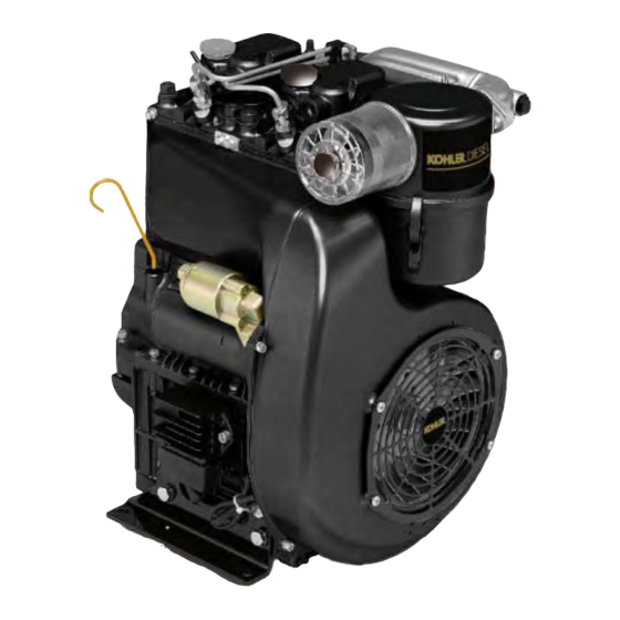
Summary of Contents for Kohler KD 477-2
- Page 1 WORKSHOP MANUAL KD 477-2...
- Page 2 KOHLER, who therefore refuses all responsibility for any injury arising from such an operation.
-
Page 3: Warranty Certificate
8 hours of use per day and 5 days per week will be used to calculate hours used. Our obligation under this warranty is expressly limited, at our option, to the replacement or repair at Kohler Co., Kohler, Wisconsin 53044, or at a service facility designated by us of such parts as inspection shall disclose to have been defective. -
Page 4: Table Of Contents
INDEX INDEX WARRANTY CERTIFICATE ............................. 3 Limited 3 year kohler ® diesel engine warranty ........................3 California emission control warranty statement ......................... 3 Your warranty rights and obligations ..........................3 I - TROUBLE SHOOTING ............................7 Possible causes and trouble shooting ..........................7 II - SAFETY AND WARNING DECALS - SAFETY INSTRUCTIONS ............... - Page 5 Checking for oil leaks .................................42 Testing engine on brake ..............................43 Running-in table ................................43 XV - STORAGE ............................... 44 Storage ..................................... 44 How to prepare the engine for operation .......................... 44 - 5 - KD 477-2 Workshop Manual_cod. ED0053029370_1° ed_ rev. 00...
- Page 6 INDEX XVI - QUICK REFERENCE CHARTS ........................45 Couplings ..................................45 Adjustments ..................................45 End floats ..................................45 Tightening torques ................................46 Standard screw tightening torques ........................... 46 - 6 - KD 477-2 Workshop Manual_cod. ED0053029370_1° ed_ rev. 00...
-
Page 7: I - Trouble Shooting
Worn or jammed piston rings Worn or scored cylinders Worn valve guides Jammed valves Worn bearings Governor linkage not free to slide Drive shaft not free to slide Damaged cylinder head gasket - 7 - KD 477-2 Workshop Manual_cod. ED0053029370_1° ed_ rev. 00... -
Page 8: Safety And Warning Decals - Safety Instructions
GENERAL NOTES . Children and animals must be kept at a sufficient distance . Kohler engines are built to provide safe and longlasting from the machine to prevent any danger resulting from its performances, but in order to obtain these results it is operation. -
Page 9: General Safety During Operating Phases
. In order to move the engine simultaneously use the eyebolts fitted for this purpose by Kohler. These lifting points are however not suitable for the entire machine, so in this case use the eyebolts fitted by the manufacturer. -
Page 10: Model Number And Identification
C) Engine serial number D) Maximum operating speed E) Number of the customer version (form K) F) Approval data Approval data The approval reference directives EC are on the engine plate (F). - 10 - KD 477-2 Workshop Manual_cod. ED0053029370_1° ed_ rev. 00... -
Page 11: Technical Data
Max.permissible driving shaft axial: continuous (instantaneous) 100(350) Flywheel site: continuous (instantaneous) 25°(35°) Max. inclination Power take off site: continuous (instantaneous) 25°(40°) Lateral: continuous (instantaneous) 25°(40°) Referred to N power Consumption at max torque - 11 - KD 477-2 Workshop Manual_cod. ED0053029370_1° ed_ rev. 00... -
Page 12: Characteristics
Max. power tolerance is 5%. Power decreases by approximately 1% every 100 m di altitude and by 2% every 5°C above 25°C. Note: Consult Kohler for power, torque curves and specific consumptions at rates differing from those given above. - 12 -... -
Page 13: Overall Dimensions
OVERALL DIMENSIONS Note: Dimensions in mm - 13 - KD 477-2 Workshop Manual_cod. ED0053029370_1° ed_ rev. 00... -
Page 14: Special Tools
Cutter Ø 38 mm (1.50 inch.) 00365R0510 Cutter Ø 40 mm (1.57 inch.) 00365R0430 Injector test bench 00365R0100 Bearing extractor 00365R0770 Cylinder collar Ø 80=85 mm (3.15=3.35 inch.) 00365R0880 Valve extractor - 14 - KD 477-2 Workshop Manual_cod. ED0053029370_1° ed_ rev. 00... -
Page 15: Maintenance - Recommended Oil Type - Refilling
45 to prevent difficult starting. Do not use dirty diesel fuel or mixtures of diesel fuel and water since this would cause serious engine faults. The capacity of the standard tank is: lt. 7.0 - 15 - KD 477-2 Workshop Manual_cod. ED0053029370_1° ed_ rev. 00... -
Page 16: Recommended Oil
MIL - L- 46152 D/E MB 226.1 MB 226.5 E1-96 MB 227.1 MB 227.5 E2-96 MB 228.1 228.3 E3-96 VW 500.00 VW 501.01 VW 505.00 VOLVO VDS MAN QC 13-017 - 16 - KD 477-2 Workshop Manual_cod. ED0053029370_1° ed_ rev. 00... -
Page 17: Disassembly Of The Engine
DISASSEMBLY AND REASSEMBLY Besides disassembly and reassembly operations this chapter also includes checking and setting specifications, dimensions, repair and operating instructions. Always use original Kohler spare parts for re- pair operations. Flywheel extraction Use extractor cod. 00365R0020, as shown in figure 1. -
Page 18: Checks And Overhaul
Cut dimensions for valve seats Inlet Outlet Engine A x B Ø guide A x B Ø guide KD 477-2 40 x 12 mm 7 mm 38 x 12 mm 7 mm - 18 - KD 477-2 Workshop Manual_cod. ED0053029370_1° ed_ rev. 00... - Page 19 If the resulting bounce is considera- ble and uniform, also when the valve is rotated, it means that the fit is good. If not, continue grinding until the conditions described above are achieved. - 19 - KD 477-2 Workshop Manual_cod. ED0053029370_1° ed_ rev. 00...
-
Page 20: Valves And Springs
The cylinder surface which comes into contact with piston rings should be machined with the plateau method. If the taper and ovality of the cylinder exceed the values indicated, then the cylinder and piston must be renewed. - 20 - KD 477-2 Workshop Manual_cod. ED0053029370_1° ed_ rev. 00... -
Page 21: Piston Rings - Pistons - Piston Pins
Check the clearance between cylinder and piston, if it is greater than 0.120 mm both cylinder and piston must be replaced. Assembly clearance between piston pin and piston in millimetres: Fitting mm Max. wear mm 0,001 ÷ 0,010 0,060 - 21 - KD 477-2 Workshop Manual_cod. ED0053029370_1° ed_ rev. 00... -
Page 22: Connecting Rods
Should the distortion exceed this value (max 0.10 mm), re- set connecting rod as follows: Place connecting rod stem on checking bench and apply a cali- brated pressure to the convex side of the stem (fig. 22). - 22 - KD 477-2 Workshop Manual_cod. ED0053029370_1° ed_ rev. 00... -
Page 23: Crankshaft
26 so as not to create crack initiation sections on the crankshaft. - 23 - KD 477-2 Workshop Manual_cod. ED0053029370_1° ed_ rev. 00... -
Page 24: Camshaft
Make sure the tappet surfaces are not worn, lined or present signs of seizure. If so, replace. Tappet and seat check in mm (fig. 29). Measurement Fitting mm Max .assy.clearance mm Tappet 11,98 ÷ 11,99 0,10 Tappet seat 12,00 ÷ 12,018 - 24 - KD 477-2 Workshop Manual_cod. ED0053029370_1° ed_ rev. 00... -
Page 25: Governor Lever And Spring
Fitting mm Max. wear mm 0,094 ÷ 0,144 0,294 The axial clearance of the rotors (fig. 32) should be between: Fitting mm Max. wear mm 0,010 ÷ 0,050 0,100 - 25 - KD 477-2 Workshop Manual_cod. ED0053029370_1° ed_ rev. 00... -
Page 26: Injection Equipment
Replace valve if the fall in pressure exceeds 50 kg/cm² and con- tinues to fall slowly. Injection pump setting Register eccentric dowel to the maximum capacity of the pumping elements (q, fig. 39). - 26 - KD 477-2 Workshop Manual_cod. ED0053029370_1° ed_ rev. 00... -
Page 27: Injection Pump Assembly
2.0 to 2.1 mm. 7. Check pressure seal again, as described in paragraph "Checking injection pump" page 26, to make sure the replaced parts are working properly. - 27 - KD 477-2 Workshop Manual_cod. ED0053029370_1° ed_ rev. 00... -
Page 28: Testing Air Tightness
5. When setting is complete, while still at the test bench, run pum- ping elements a few times and check the amount of diesel that passes through the upper leak-off of the injector (fig. 43). - 28 - KD 477-2 Workshop Manual_cod. ED0053029370_1° ed_ rev. 00... -
Page 29: Electrical Equipment
7. If the charging current cuts out or is lower than the values given above, replace governor. If the performance does not improve af- ter this replacement, the trouble must be locked for in the alterna- tor. - 29 - KD 477-2 Workshop Manual_cod. ED0053029370_1° ed_ rev. 00... -
Page 30: Alternator Checking (Stator)
The voltage regulator will be damaged beyond repair, if it is run with the battery cables disconnected or with unactiva- ted batteries. - 30 - KD 477-2 Workshop Manual_cod. ED0053029370_1° ed_ rev. 00... -
Page 31: Diagram Of Electric Starting Wiring System With Flywheel Alternator
Diagram of electric starting wiring system with external alternator (fig. 48). 1.Battery - 2.Regulator - 3.Alternator - 4.Starter motor - 5.Pressure gauge - 6.Oil pressure warning light - 7.Starter key - 8.Battery char- ging light. - 31 - KD 477-2 Workshop Manual_cod. ED0053029370_1° ed_ rev. 00... -
Page 32: Engine Assembly
The balance between the two forces keeps the revolutions practically constant when load is changed. For pre-load adjustment of the speed governor see paragraph on page 40 "Injection pump tie rod connection". - 32 - KD 477-2 Workshop Manual_cod. ED0053029370_1° ed_ rev. 00... -
Page 33: Crankshaft Preparation
(fig. 56). It is advisable to spread a bit of rubber adhesive round the edges of the rubber gasket for better seal. - 33 - KD 477-2 Workshop Manual_cod. ED0053029370_1° ed_ rev. 00... -
Page 34: Timing Cover Assembly
(fig. 60). 0.2 and 0.3 mm shims are available. - 34 - KD 477-2 Workshop Manual_cod. ED0053029370_1° ed_ rev. 00... -
Page 35: Fitting Of Oil Seal Rings
(fig. 63). Make sure the O-Ring on the oil pump cover is in perfect condition. Tighten screws gradually to a pressure of: kgm 1 (Nm 9,8) - 35 - KD 477-2 Workshop Manual_cod. ED0053029370_1° ed_ rev. 00... -
Page 36: Feeding Pump Assembly
(fig. 67). The coupling clearance between big end bearing and pins is: 0.020 to 0.072 mm. Tighten up connecting rod bolts to: kgm 3,8 ÷ 4 (37,3 ÷ 39,3 Nm) - 36 - KD 477-2 Workshop Manual_cod. ED0053029370_1° ed_ rev. 00... -
Page 37: Piston Ring Fitting
The lower end of the cylinder is chamfered for piston ring insertion (fig. 71). The operation can be carried out easily by using a standard piston ring compression tool (tool 00365R0770). - 37 - KD 477-2 Workshop Manual_cod. ED0053029370_1° ed_ rev. 00... -
Page 38: Cylinder Height Adjustement
Before mounting the heads on the cylinders, insert injectors in their housings and after having secured them temporarily, check protusion of nozzles from head surface (fig. 75). Protusion S should be: 2,25 ÷ 2,75 mm - 38 - KD 477-2 Workshop Manual_cod. ED0053029370_1° ed_ rev. 00... -
Page 39: Fitting Cylinder Heads
The clearance between valves and rockers with the engine cold (fig. 79) is: 0,15 mm intake/exhaust The operation must be carried out with the pistons at their top dead center compression position. - 39 - KD 477-2 Workshop Manual_cod. ED0053029370_1° ed_ rev. 00... -
Page 40: Injection Pump Fitting
(fig. 83). If the flywheel has to be replaced, transfer and punch the above men- tioned indications on the new one. - 40 - KD 477-2 Workshop Manual_cod. ED0053029370_1° ed_ rev. 00... -
Page 41: Checking Start Of Injection
40 and the start of injection according to the following table: I.P. Ø flywheel 26° 53,5 mm 236 mm - 41 - KD 477-2 Workshop Manual_cod. ED0053029370_1° ed_ rev. 00... -
Page 42: Engine Testing
2. Start engine and run for a few minutes. The pressure which forms inside the crankcase bring out any oil leaks. 3. Re-fit gas collection pipe to suction manifold. - 42 - KD 477-2 Workshop Manual_cod. ED0053029370_1° ed_ rev. 00... -
Page 43: Testing Engine On Brake
Delivery of diesel fuel is correctly calibrated when the exhaust gas is slightly coloured by smoke; change the adjustment if necessary by turning the adjustment screw (fig. 94). - 43 - KD 477-2 Workshop Manual_cod. ED0053029370_1° ed_ rev. 00... -
Page 44: Storage
• Remove antirust with an appropriate solvent or degreaser. • Remove injector, fill with standard oil, turn crankshaft by a few revolutions, remove oil pan and drain the protective oil. - 44 - KD 477-2 Workshop Manual_cod. ED0053029370_1° ed_ rev. 00... -
Page 45: Couplings
Dead space between cylinder face and piston 2,25 2,75 Protrusion of injector MIN (mm) MAX (mm) End floats 0,10 0,20 Crankshaft 0,10 0,20 Camshaft 0,01 0,05 Oil pump shaft - 45 - KD 477-2 Workshop Manual_cod. ED0053029370_1° ed_ rev. 00... -
Page 46: Tightening Torques
29,50 35,40 16 x 2,00 26,30 37,00 44,40 18 x 2,50 36,60 51,50 61,80 20 x 2,50 44,40 62,40 74,90 22 x 2,50 56,90 80,00 96,00 24 x 3,00 - 46 - KD 477-2 Workshop Manual_cod. ED0053029370_1° ed_ rev. 00... - Page 47 NOTE - 47 - KD 477-2 Workshop Manual_cod. ED0053029370_1° ed_ rev. 00...
- Page 48 Translated from the original manual in Italian language. Data reported in this issue can be modified at any time by KOHLER. FOR SALES AND SERVICE INFORMATION IN U.S. AND CANADA, CALL 1-800-544-2444 FORM NO. ED0053029370 KohlerEngines.com ISSUED 05/07/2012 ENGINE DIVISION, KOHLER CO., KOHLER, WISCONSIN 53044...
Need help?
Do you have a question about the KD 477-2 and is the answer not in the manual?
Questions and answers