Table of Contents
Advertisement
Quick Links
Advertisement
Table of Contents

Related Manuals for Ikegami MKC-500HD


Summary of Contents for Ikegami MKC-500HD
- Page 1 MKC-500HD Digital Process Compact 3CMOS Color Camera...
- Page 2 The copyright of the software made for this product is in Ikegami Tsushinki Co., Ltd. It forbids to reproduction, a change, and so on about DN-29403...
-
Page 3: Safety Precautions
If the unit is used as it is, a fire or electric shock The copyright of the software made for this may be caused. Contact the dealer or sales product is in Ikegami Tsushinki Co., Ltd. representative. It forbids to reproduction, a change, and so on... - Page 4 The MKC-500HD is not AP APG equipment. humidifier. As this unit is heavy (over 10Kg), carry it by 2 or more The BATTERY for BT1 in MKC-500HD, that should be persons. If it is carried by one person, it may turn down or drop,...
- Page 5 Guidance and manufacturer's declaration - electromagnetic emissions The Model MKC-500HD is intended for use in the electromagnetic environment specified below. The customer or the user of the Model MKC-500HD should assure that it is used in such an environment. Emissions test...
- Page 6 Guidance and manufacturer's declaration - electromagnetic emissions The Model MKC-500HD is intended for use in the electromagnetic environment specified below. The customer or the user of the Model MKC-500HD should assure that it is used in such an environment. Immunity test...
-
Page 7: Table Of Contents
CONTENTS Name and Function of Each Parts ................6 Camera Head......................6 Front Panel of Camera Control Unit (CCU) ............. 7 Rear Panel of Camera Control Unit (CCU)............. 11 Operation ........................13 Connection ........................ 13 Electrical Connection ....................14 Setting Auto White Balance..................15 Menu Operation ....................... -
Page 8: Name And Function Of Each Parts
Name and Function of Each Parts Camera Head Rear View Side View Lens Connector 1/3” C-mount CAMERA 1/3” C-mount Mount for connecting the lens and microscope adapter. Lens Connector Used to connect the Iris cable of the special microscope adapter and 1/3” C-mount lens. -
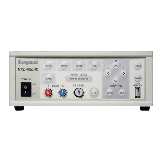
Page 9: Front Panel Of Camera Control Unit (Ccu)
Menu Switch Power Switch To power on/off MKC-500HD. When this switch is turned on, the logo of "Ikegami" lights up blue. Pressing the top of the switch turns on power, and pressing the bottom of the switch turns off power. When this switch is turned on, the picture is output in the state where power was last turned off. - Page 10 Auto White Balance Switch To execute Auto White Balance. Use this switch, when the camera is not used for a certain time, color balance is not proper, and the light source changes. To control the white balance, project a white photographic object and adjust the iris just before LEVEL INDICATOR lights up red.
- Page 11 Picture Save Switch Press the switch to acquire the still picture from the camera into USB storage connected to 17USB connector. The picture quality is 1920x1080 pixels at Bitmap format (non-compressed) or 1920x1080 pixels at JPEG format. The stored picture quality can be adjusted on the menu.
- Page 12 Arrow Key To select a scene file among 1, 2, 3 and Function. The scene file setting can be fixed through the menu. When selecting an item you want to set on the menu, move cursor by clicking Arrow Keys , and changing the contents of the item you want to set, choose the value you have set by clicking Arrow Keys USB Connector...
-
Page 13: Rear Panel Of Camera Control Unit (Ccu)
Rear Panel of Camera Control Unit (CCU) VBS Output Connector USB Connector S-VIDEO Output Connector DVI-D Output Connector SD RGB Output Connector Genlock Input Connector Foot Switch Connector HD RGB Output Connector HD-SDI Output Connector Potential Equalization Camera Connector Camera Connector Connect the camera cable from the camera head. - Page 14 HD RGB Output Connector Output HD RGB video signal. YPbPr video signal output is also available by changing the setting on the menu. Refer to “Video Setting” (Page 20) for further detailed operations. Connect a RGB Video Cable (Option) to a RGB input interfaced monitor. VBS Output Connector (SD) Output SD video signal.
-
Page 15: Operation
Camera Head DVI interfaced equipment DVD recorder DVI-D cable AC outlet S-VIDEO cable MKC-500HD CCU Rear Panel Camera cable Coaxial cable RGB cable Foot Switch Monitor * Terminate the output from RGB OUT and VIDEO OUT at 75ohms on the receiver side. -
Page 16: Electrical Connection
In case of fast moving object on a video image, it may appear distortions. Note1 When power is turned off in the state of still screen picture, that state will not be held even if power is turned on again, and MKC-500HD is set to the normal shooting state. DN-29403... -
Page 17: Setting Auto White Balance
Usually, MKC-500HD can be operated immediately after turning the power switch on. Therefore, any other operations are unnecessary. However, when using MKC-500HD for the first time, or when the light source has been changed, Auto White Balance setting is required. -
Page 18: Menu Operation
Menu Operation MKC-500HD has various useful and practical functions. The user can select and set these functions on the menu. The basic operation is as follows. Operation Method Pressing the Menu switch (ref. page 7) on the front panel of CCU displays a menu on the monitoring screen, on which various camera functions can be set. -
Page 19: Video Adjust
Video Adjust Used to adjust the level of black, red and blue of video picture. Video Adjust QUIT Master Pedestal Gain Offset Blue Color Corrector Green Blue Yellow Cyan Magenta Video Phase Horizontal Vertical [Master Pedestal] Used to change the master pedestal value by Arrow Keys . -
Page 20: Ae Mode
[Red] Possible to change the level of red only. [Green] Possible to change the level of green only. [Blue] Possible to change the level of blue only. [Yellow] Possible to change the level of yellow only. [Cyan] Possible to change the level of cyan only. [Magenta] Possible to change the level of magenta only. - Page 21 Electronic Shutter Switch (ref. Page7) and Automatic Gain Control Switch on the Front Panel of CCU are turned on. It has the same function as Brightness Control Volume on the Front Panel of CCU. [AE Speed] Used to select the response rate of the Electronic Shutter and Automatic Gain Control from among Middle, Fast and Slow.
-
Page 22: Dtl Set
DTL Set Used to adjust detail enhancement. DTL Set QUIT DTL Gain Skin DTL Gain Boost Frequency 8.0MHz DTL Thresh Slim DTL [DTL] Set it to ON usually. Used to turn on an off whole picture detail enhancement. When it is set to OFF, the detail enhancement switch on the Front Panel of CCU is not operative. -
Page 23: Video Setting
Video Setting To select display method for the still picture. Video Setting QUIT Format. 1080i/59 Aspect 16:9 Analog Output YPbPr Freeze Mode Frame Gamma Master Gamma Color Sat Color Sat Gain [Format] Select the video signal format among 1080i/59.94, 1080i/50. 720P/59.94 720P/50. -
Page 24: Video Matrix
Video Matrix The following menu items can be selected by first selecting [Miscellaneous], going to [Menu Mode] and selecting “Advanced” (ref. Page 27). Carries out color tone change with a six-axis matrix. Video Matrix QUIT Matrix [Matrix] When turned ON, it is possible to carry out RGB conversion with a six-axis matrix. -
Page 25: Scene File
[Auto White Shade] Carries out automatic correction of the lens aberration. Unless this adjustment is carried out while aiming at a pure white subject, it has a negative influence on the image output of the camera. This is no problem, as it is normally not used. -
Page 26: Foot Switch Mode
Foot Switch Mode Used to select the operation of the foot switch to be connected. Foot Switch Mode QUIT Foot Switch Save Scene File Freeze Freeze [Foot Switch S1] Select a function of the black foot switch from among Screen control (Freeze), Save (Still picture store), Scene File, Fluorescein, Frip, Mirorr and Rotate. -
Page 27: Inverse
Inverse To select the video image inverse (Top and Down, Right and Left) Inverse QUIT Horizontal Vertical [Horizontal] Select ON to inverse the video image Right to Left. [Vertical] Select ON to inverse the video image Bottom to Top. STILL Setting Used to set the quality of a still picture to be stored in an external device (USB memory) STILL Setting... -
Page 28: Date/Time Adjust
Date/Time Adjust To set Date and Time. Date/Time Adjust QUIT Year 2009 Mouth Hour Minute Adjust Ready When Date and Time have been changed, move to “Adjust” and select “Start” before quit the menu. DVI Setting To set DVI output signal format. DVI Setting QUIT Format... -
Page 29: Down Converter Setting
Down Converter setting To set analogue video signal mode of Down Converter output. Down Converter setting QUIT Format Side Cut Analog Output [Format] To set analogue video format from among Side Cut size, Letter Box size and Squeeze size. [Analog Output] To set analogue video format from RGB format and YCbCr. -
Page 30: Version Info
[Genlock] Gen Lock: Used to obtain synchronization of output signals with another camera, such as when using as a 3D camera, etc. [Horizontal] Adjusts the horizontal phase. [Vertical] Adjusts the vertical phase. [Centre Marker] To display a marker to adjust a centre point. [Menu Mode] Sets the displayed menu. -
Page 31: Specification
Specification Ratings Optics RGB Prism method Sensor Scanning System 1125 / 59.94Hz Progressive Scan Image Pickup Device 1/3-inch 2,07M pixels CMOS x 3 Effective Pixels 1920(H)× 1080(V) Lens Mount C-Mount Video Output 2:1 Interlace 1125 Line/60 Field, 30 Frame Aspect Ratio H16:V9 Output Video Signal HDTV Output... -
Page 32: Performance
100g or less CCU: W210xH80xD300mm (without protrusion) 2.5kg or less Accessories AC Power Cable KP320/KS31 SJT 3 , USB memory Performance Resolutions Horizontal 1000TV Lines S/N Ratio 54dB ( and Detail Off, Encoder output) Sensitivity Standard 2000lux F12/3200K Registration Error Full Screen within 0.05% Functions Image Flip and Turn... -
Page 33: External Appearance
External Appearance Camera Head Unit: mm DN-29403... - Page 34 DN-29403...
- Page 35 Operation Manual First Issue February 2012 Published by Ikegami Tsushinki Co., Ltd. It forbids to copy it without notice and to reproduce it about a part of this manual or all as for any method as well without taking the assent of Ikegami Tsushinki Co., Ltd.
- Page 36 5-6-16, Ikegami, Ohta-ku, Tokyo, 146 Japan Phone: 03-5700-1111, Fax: 03-5700-1137 Ikegami Electronics (U.S.A.), Inc. 37 Brook Avenue, Maywood, New Jersey 07607, U.S.A. Phone: (201)368-9171, Fax: (201)569-1626 Ikegami Electronics (Europe) GmbH Ikegami strasse 1, 41460 Neuss 1, F.R Germany Phone: (02131)123-0, Fax: 02131)102820 DN-29403...
Need help?
Do you have a question about the MKC-500HD and is the answer not in the manual?
Questions and answers