
Related Manuals for Ikegami HDL-4500


Summary of Contents for Ikegami HDL-4500
- Page 1 ND FILTER 1. 100% 6.2% 1.6% Products conforming to RoHS directive HDL-4500 3CMOS Super High Sensitive HDTV camera Operation Manual...
- Page 3 ND FILTER 1. 100% 6.2% 1.6% Products conforming to RoHS directive HDL-4500 3CMOS Super High Sensitive HDTV camera Operation Manual 1406 1st Edition (U) (E)
- Page 4 Copyright © 2014 Ikegami Tsushinki Co., Ltd. We reserve the copyright on the software we create. No part of this publication may be modified or reproduced in any form, or by any means, without prior written permission from Ikegami Tsushinki Co., Ltd.
- Page 5 PRODUCTS CONFORMING TO RoHS DIRECTIVE Following products described in this manual are products conforming to RoHS directive. ・ HDL-4500 HDTV Camera Products conforming to RoHS directive include products that do not contain specified hazardous substances such as lead, mercury, cadmium, hexavalent chromium, polybrominated biphenyl (PBB) and polybrominated diphenyl ether (PBDE) in electrical and electronic equipment excluding following exemption applications based on the EU directive.
-
Page 6: Maintenance Of Products Conforming To Rohs Directive
・ If the customer mixed the lead-solder with the main body wiring or the circuit board, it becomes guarantee off the subject. Ikegami doesn’t guarantee to do the repair work. Because the solder polluted with lead cannot be removed. 3. Parts... -
Page 7: Information To The User
The CE mark means that the following products will meet the Directives 2004/108/EC and standards EN55022, EN55024. ・ HDL-4500 : HDTV CAMERA Use shielded cable except AC cable. This equipment is not intended for use in residential areas, so that use in residential areas may cause interference. -
Page 8: Notes On Using In Safety
NOTES ON USING IN SAFETY NOTES ON USING IN SAFETY The followings are for your safe use of this product. Please peruse them before you start using. 1. Notes on this manual (1) This manual is written assuming that readers have a basic knowledge of cameras, so the technical terms are not described here. - Page 9 This product includes parts that wear out and have a limited life even in proper use or storage. Therefore, regular maintenance is recommended to extend the life and safe use of this product for a long time. Please contact Ikegami’s sales and service centers for...
-
Page 10: How To Use Operation Manual
HOW TO USE OPERATION MANUAL HOW TO USE OPERATION MANUAL This operation manual is intended to describe how to operate the HDL-4500 3CMOS Super High Sensitive HDTV camera (mentioned as HD Camera hereafter). This operation manual is written for people who have some basic knowledge and understanding of a television camera, so explanation of technical terms is omitted herein. -
Page 11: Table Of Contents
CONTENTS - 1 HDL-4500 OPERATION MANUAL (TABLE OF CONTENTS) PRODUCTS CONFORMING TO RoHS DIRECTIVE MAINTENANCE OF PRODUCTS CONFORMING TO RoHS DIRECTIVE INFORMATION TO THE USER NOTES ON USING IN SAFETY HOW TO USE OPERATION MANUAL 1. OUTLINE ............................1-1 2. FEATURES ...........................2-1 3. - Page 12 OCP-100 OCP-100 1209 VOL1 (J)
-
Page 13: Outline
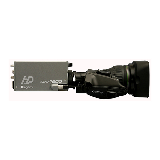
1. OUTLINE 1. OUTLINE The HDL-4500 is a 3CMOS ultrasensitive HDTV camera that employs Ikegami’s leading-edge camera technology and front line digital technology to realize the highest sensitivity and picture quality. A high-speed multi-sampling type ultrasensitive 1.3 Mega pixel CMOS sensor makes it possible to obtain sufficient sensitivity without lighting, even when shooting by moonlight at night. -
Page 14: Features
■ Includes digital process LSI (ASIC) Features a digital process LSI (ASIC) with an internal process (operation) of max. 38 bits, which is the same as that for Ikegami's broadcast-use studio HDTV camera. Even non-linear processing, such as white shading correction or gamma correction, are digitalized in the camera head to realize consistently high image quality and reliability. - Page 15 2. FEATURES Operation with viewfinder on the shoulder If the optional VF attachment is mounted, it is possible to attach a 2-inch color viewfinder and use as a portable camera on the shoulder. The viewfinder displays the menu, camera photography information and the VF marker. Camera photography information : GAIN.
-
Page 16: Name And Function Of Each Part
3. NAME and FUNCTION of EACH PART 3. NAME and FUNCTION of EACH PART 3.1 Front View / Right Side View / Bottom View Front View Right Side View ① ND FILTER 1. 100% 6.2% 1.6% ③ ⑥ ② Bottom View ④... -
Page 17: Rear View
3. NAME and FUNCTION of EACH PART 3.2 Rear View ② SDI OUT ③ ① COMM ④ EXT SYNC WARNING GAIN ⑮ ⑤ ⑭ ⑥ ⑬ POWER ⑫ ⑦ ⑪ ⑧ MENU DC IN ⑨ ⑩ ① FAN ⑥ G.L indicator ⑪... - Page 18 3. NAME and FUNCTION of EACH PART ⑧ AWB/ABB indicator Lights up during execution of AWB or ABB. - AWB (Auto White Balance) execution : Lights up Green - ABB (Auto Black Balance) execution : Lights up Orange - Completion of AWB or ABB : Turn off automatically - Incompletion / N.G of AWB : Green blinking...
-
Page 19: Installation And Connections
4. INSTALLATION and CONNECTIONS 4. INSTALLATION and CONNECTIONS 4.1 System Setup Diagram Tripod Head System Control Box HDL-4500 LENS ND FILTER SDI OUT Coaxial Cable (Max:100m) Zoom Lens 1. 100% 6.2% 1.6% Teleside MON OUT Converter COMMAND HD Monitor (COLOR) -
Page 20: Tripod Installation
4. INSTALLATION and CONNECTIONS 4.2 Tripod Installation This section explains how to install the camera to the tripod. There are two ways to install the camera: one is to install it directly to the tripod and the other is to use the dedicated tripod mount plate (optionally available). -
Page 21: Lens Mounting
4. INSTALLATION and CONNECTIONS 3. Set the T-230 tripod mount plate with camera body on the tripod. Make sure that the camera is fastened to the tripod mount plate and not loose. 4.3 Lens Mounting This section explains how to mount the lens on. Position mark Bayonet ring knob Red mark (position mark) -
Page 22: Connection Of Monitor
4. INSTALLATION and CONNECTIONS Camera rear view SDI OUT AC connector COMM AC outlet POWER EXT SYNC indicator WARNING GAIN POWER POWER switch AC pack MENU DC IN DC OUT connector POWER switch DC IN connector DC POWER cable 1. Connect AC connector to an AC power outlet to which commercial power is supplied. 2. -
Page 23: Connection Of Operation Control Panel (Ocp-200, Etc.)
4. INSTALLATION and CONNECTIONS [ SDI output ] HD MONITOR (Color) HD SDI IN SDI OUT SDI OUT Connector COMM EXT SYNC WARNING GAIN POWER MENU Coax cable DC IN Camera rear view 1. With the coax cable, connect the SDI OUT connectors on the rear of the camera to the HDTV monitor. Also, perform 75Ω termination at HD MONITOR side. - Page 24 4. INSTALLATION and CONNECTIONS ・When OCP-200, etc. is connected, following controls can be performed. ・ To use as a single operation control panel, put it in the dedicated case (optionally available). This enables direct connection to the camera. ON/OFF Control Items Control Analog Control Items Control...
-
Page 25: Connection Of External Sync Signal For Genlock
4. INSTALLATION and CONNECTIONS 4.7 Connection of External SYNC Signal for Genlock Camera rear view SDI OUT COMM EXT SYNC WARNING GAIN EXT SYNC connector POWER MENU DC IN External SYNC signal External system 1. EXT SYNC connector is used to input the SYNC signal of the external system desired to be genlocked with the equipment. When the synchronizing the camera with the SYNC signal of external system, G.L indicator lights up green. -
Page 26: Operation
5. OPERATION 5. OPERATION 5.1 Power Supply Injection After connecting the camera with the peripheral system components, set the POWER switch on the camera rear panel to “ON” and check to be sure that the POWER indicator comes on. Display the image output of the camera on the HDTV color monitor connected with the camera. Be sure to set the POWER switch of the camera to “OFF”... -
Page 27: Auto Iris Control
5. OPERATION Day light After sunrise / Before sunset Clear Slight cloudy Cloudy 8000 9000 2000 2500 3000 3500 4000 4500 5000 5500 6000 6500 7000 7500 8500 10000 K Reflector lamp for photo Incandescence Candle - light Halogen lamp Strobo / Fluorescent lamp The human eye adapts to a changing environment--the color balance for it will not be disturbed seriously even if color temperature varies according to the environmental conditions and stored data. -
Page 28: Camera Menu
5. OPERATION 5.3 Camera Menu Enter the menu by pressing and holding the MENU select switch located on the rear side of the HDL-4500 for more than one second. Select an item in the menu to change the mode. To move to the next menu, select “NEXT PAGE” and press the MENU select switch. - Page 29 5. OPERATION *** MENU PAGE1 *** (-6, 0, +6, +12, +18, +24, +30, +36, +42, +48, +54, NEXT PAGE +60, +66, +72, +78) STEP GAIN 0 dB GAMMA SELECT (0.45, 0.4, 0.35, OFF)(NORMAL, CINE1, CINE2) 0.45 (NORMAL) (-11%, -9%, -7%, -5%, -3%, OFF, +3%, +5%, +7%, BLK PRS/STR +9%, +11%)...
- Page 30 5. OPERATION FILTER SELECT QUIT (1, 2, 3, 4) B(5600) (A(3200), B(5600)) ND : Switches over ND filter. CC : Switches over electric color temperature (ECC) filter. The values for ND and CC vary depending on “ON” or “OFF” for SINGLE FILTER MODE in the engineer menu. [ MENU PAGE 2 ] 1.
- Page 31 5. OPERATION ■ GAMMA If the MENU select switch is pressed while any of “M”, “B”, or “R” is blinking, the value below it can be changed. Selecting “M CLR” makes the system to be set back to the factory setup. GAMMA QUIT M CLR...
- Page 32 5. OPERATION R CH H : Adjusts H rate for R ch. R CH V : Adjusts V rate for R ch. G CH H : Adjusts H rate for G ch. G CH V : Adjusts V rate for G ch. B CH H : Adjusts H rate for B ch.
- Page 33 5. OPERATION ● B CH H B CH H If the MENU select switch is pressed while any of “H SAW” or “H PARA” is blinking, the value below it can be changed. Selecting “M CLR” makes the system to be set back to the factory setup.
- Page 34 5. OPERATION GAIN : Adjusts correction volume of outline. FREQUENCY : Adjusts central frequency. The higher the frequency becomes, the narrower the width of edge signal becomes. BLACK WHITE : Adjusts the balance of edge volume between the light part and the dark part. BALANCE : Adjusts the balance of edge volume between horizontal direction and vertical direction.
- Page 35 5. OPERATION 5-10 ■ LOW/MID/HIGH GAIN MODE When the MENU select switch is pressed on the item LOW/MID/HIGH GAIN MODE to be set, the value on the right blinks. Keeping this state, turn the MENU select switch to set the value QUIT (-6dB to +78dB).
- Page 36 files are available and two statuses - extender OFF and extender ON - can be stored in each file. The data is selected automatically by answer signals from the lens. White shading, flare, gain and gamma are stored in a lens file. When the HDL-4500 is shipped, the compensation data based on the factory standard lens is registered in No.
- Page 37 5. OPERATION 5-12 [ Making lens file ] Make a lens file. Check the following in making a lens file. ・ Creating a lens file requires precise adjustment. Do not update a lens file without discretion. ・ Prepare a uniform white chart on which Kent paper is stuck as a subject. A registration chart is inappropriate as a subject. ・...
- Page 38 5-13 5. OPERATION [Editing lens file name] The “AUTO SELECT NAME EDIT” (the edit of lens name used for the lens file auto selection) can be operated by the following procedure. 1. Sets the blinking cursor to “NUMBER” and press “SET”. LENS SELECT 2.
- Page 39 5. OPERATION 5-14 ● About AUTO SEL NAME EDIT display AUTO SEL NAME EDIT QUIT AUTO SEL NAME EDIT (AB40X10ABCD Display part of the lens name to edit Displays the model name of the lens to edit. NOW CONNECTED LENS (AB40X10ABCD Display part of the lens name to connect Displays the model name of the lens...
- Page 40 5-15 5. OPERATION [MAGNIFICANT] X1.5 : Magnifies X1.5 : Magnifies X2 : Magnifies X3 : Magnifies X4 : Magnifies X6 : Magnifies X8 X10 : Magnifies X10 [DTL GAIN&FRQ SET] When the digital extender is turned on, the gain, the booth, and the frequency of DTL can be changed according to the expansion magnification.
- Page 41 5. OPERATION 5-16 ■ PIX ADD SELECT Sets the horizontal pixel addition. PIX ADD SELECT QUIT (+12/+18/+24/+30/+36/+42/+48/+54/+60/+66/+72/+78dB / H ADD SELECT +18dB OFF) H ADD SELECT Sets the gain for starting the horizontal pixel addition. The horizontal pixel addition is executed when the gain increase becomes over the setting.
- Page 42 5-17 5. OPERATION When the brightest ND filter is used before the extender is turned on, the ND filter is not switched. When the darkest ND filter is used before the extender is turned off, the ND filter is not switched. When the ND filter position (order or density) is changed to other than the standard, please do not use this function.
- Page 43 5. OPERATION 5-18 [AWB CC CONTROL] Sets the mode for which the ECC filter is automatically switched when AWB is performed. ・ ON : The ECC filter is automatically switched. ・ OFF : The ECC filter is not automatically switched. AWB CC CONTROL is the function to perform AWB again by switching the ECC filter automatically when the color temperature of the subject does not fit with the ECC filter position of the camera.
- Page 44 5-19 5. OPERATION [Correction Method] 1. Select “MANUAL DPC” on page 4 of the menu and press the MENU switch. The MANUAL DPC sub-menu is displayed. 2. Confirm that DPC is ON. If it is OFF, rotate the MENU switch, align the blinking cursor with DPC and press the MENU switch. The blinking cursor will move to the mode.
- Page 45 5. OPERATION 5-20 [MENU PAGE 5] 1. “MENU PAGE 5” has the following items included. 2. To select the desired item, turn and press the MENU select switch while the item is blinking. The sub menu screen of the selected item is displayed. 3.
- Page 46 5-21 5. OPERATION [DISPLAY MODE SELECT] Selects the content to be displayed. DISPLAY MODE SELECT QUIT (OFF, ON) GAIN (OFF, ON) ND FILTER (OFF, ON) CC FILTER AWB CH/ATW (OFF, ON) SHUTTER (OFF, ON) OPT EXTENDER (OFF, ON) DIG EXTENDER (OFF, ON)...
- Page 47 5. OPERATION 5-22 [ZEBRA SETTING] Sets the zebra signals. The zebra signals are striped patterns that appear superimposed on the video. There are two types of zebra signals: the zebra 1 signal which appears in the area where the video level of the subject is higher than the set value for “ZEBRA1 DETECT”, and the zebra 2 signal which appears only in the area where the video level is the same as the set value for “ZEBRA2 DETECT”.
- Page 48 5-23 5. OPERATION ■ BARS MODE FULL BARS MODE QUIT BARS TYPE FULL (FULL, ARIB) ARIB BARS TYPE ARIB (100%, 75%, + I) White 100% , White 75% , When the MENU select switch is pressed on the item to be set, the value on the right blinks. Keeping this state, turn the MENU select switch to select the desired value and press it.
- Page 49 123.4H SUB TIME 12.3H VERSION COPYRIGHT(C)2014 IKEGAMI TSUSHINKI CO. LTD. SWITCH : Displays the setting state of the dip switches in the MPU module. WORKING TIME : Displays accumulated operation time of the camera up to now. SUB TIME : Displays accumulated operation time of the camera.
-
Page 50: Engineer Menu
5-25 5. OPERATION [WORKING TIME] Displays accumulated operation time since the shipment. [SUB TIME] Displays the accumulated operation time of the camera. Unlike “WORKING TIME”, this can be reset by a user. 1. Select “SUB TIME” and press the MENU switch. The blinking cursor moves to the mode. 2. - Page 51 5. OPERATION 5-26 [Displaying the engineer menu screen] 1. Set the CAM/BAR select switch on the camera rear panel to the “BAR” position. 2. Keep on pressing the MENU switch until the WARNING indicator lights. 3. The engineer menu screen is displayed when the WARNING indicator lights. The camera menu screen is redisplayed automatically when the engineer menu screen is exited.
- Page 52 5-27 5. OPERATION [ Hierarchical Structure of the Engineer Menus ] *** ENGINEER PAGE1 (1/2) *** MAIN MENU SUB MENU SELECT DEFAULT FUNCTION NEXT PAGE Moves to ENGINEER PAGE2. SMOOTH KNEE SETUP QUIT Moves from the sub menu to the main menu. SMOOTH KNEE OFF, TYPE1, TYPE1...
- Page 53 5. OPERATION 5-28 *** ENGINEER PAGE1 (2/2) *** MAIN MENU SUB MENU SELECT DEFAULT FUNCTION ATW SETUP QUIT Moves from the sub menu to the main menu. ATW DAY MODE PRESET, NORMAL PRESET ATW allowable range at AVC OFF, AVC DAY MODE. ATW NIGHT MODE PRESET, NORMAL NORMAL ATW allowable range at AVC NIGHT MODE.
- Page 54 5-29 5. OPERATION *** ENGINEER PAGE3 *** MAIN MENU SUB MENU SELECT DEFAULT FUNCTION NEXT PAGE Moves to ENGINEER PAGE4. IRIS CIRCUIT ADJUST QUIT Moves from the sub menu to the main menu. ADJUST MODE Adjusts the relationship between the fixed iris value and the answer value. FILTER SETUP QUIT Moves from the sub menu to the main menu.
- Page 55 5. OPERATION 5-30 About the operation of the AVC function The following section describes about the AVC function, and the parameter setting value in the ENGINEER MENU PAGE1 AVC SETUP item. When the AVC function is operated (MENU PAGE3 AVC SELECT ON), the AVC function is controlled automatically to always keep an appropriate image level by using the auto iris, the auto gain control, and the ND filter.
- Page 56 5-31 5. OPERATION ① When [AVC MODE] is selected, the menu is displayed as shown below. AVC SETUP QUIT AVC DISPLAY MODE (ON, OFF) PRESET DAY FILE MODE2 (MODE1∼MODE5) DAY FILE CENTER MODE3 (MODE1∼MODE5) PRESET NIGHT FILE MODE2 (MODE1∼MODE5) DAY DETECT AREA AREA4 (AREA1∼AREA7)...
- Page 57 5. OPERATION 5-32 ・PRESET NIGHT FILE Enables change from 4 patterns at the NIGHT MODE. Initial setting value of the gain increase at each mode is as follows. MODE1 : +18dB MODE2 : +18dB MODE3 : +30dB MODE4 : +36dB The convergence level of the gain increase becomes minimum at MODE1 and maximum at MODE4.
- Page 58 5-33 5. OPERATION ● When B GAIN exceeds +90 on the panel display When blue cannot be matched appropriately, the CC filter is automatically switched to A (3200K) and the color is continued to match. ● When R GAIN exceeds +90 on the panel display When red cannot be matched appropriately, the CC filter is automatically switched to B (5600K) and the color is continued to match.
- Page 59 5. OPERATION 5-34 ① When [C.TEMP SETTING RED] is selected, the menu is displayed as shown below. Changes the R ch side correction range of [PRESET] in [ATW MODE]. C.TEMP SETTING RED QUIT RED LIMIT AUTO SET (ON, OFF) RED LIMIT CONTROL (-100∼+100)...
- Page 60 5-35 5. OPERATION ③ When [ATW REFERENCE] is clicked, the menu is displayed as shown below. ATW REFERENCE QUIT ATW RED REFERENCE (-100∼+100) ATW BLUE REFERENCE (-100∼+100) ・ Adjusts the color converged when the color whose color temperature is low (Red) is matched at [ATW RED REFERENCE].
- Page 61 5. OPERATION 5-36 How to Change the Scanning Format The scanning format of ENGINEER PAGE4 can be changed according to the following procedure. ● When doing it from the operation control panel 1. Open the camera menu by the operation control panel. 2.
-
Page 62: Specifications
6. SPECIFICATIONS 6. SPECIFICATIONS 6.1 Rating Items Rating Remarks Video output format 1080/59.94i or 1080/50i 16:9 aspect ratio Image sensor 2/3-inch 1.3Mega pixel CMOS ×3 Rolling shutter Total pixels 1408 (horizontal)× 1042 (vertical) Effective picture elements 1280 (horizontal)× 720 (vertical) 16:9 aspect ratio Imaging frame rate 59.94fps or 50fps... -
Page 63: External Appearance
6. SPECIFICATIONS 6.5 External Appearance [STANDARD] 103±3 40±0.5... - Page 64 6. SPECIFICATIONS [With UP CN BOX: Optionally Available] 140±3 44.5±0.5...
-
Page 65: Changing Informatio
7. CHANGING INFORMATION 7. CHANGING INFORMATION This chapter explains revision contents in case of design revision at the request of customers. Read by comparing this information with the main part of the operation manual. - Page 67 © June 2014 Ikegami Tsushinki Co.,Ltd. ■ All rights reserved. Reproduction or duplication, without permission of Ikegami Tsushinki Co., Ltd. of editorial or pictorial content in whole or in part, in any manner, is prohibited. ■ Specifications and design are subject to change without prior notice.
- Page 70 Ikegami Tsushinki Co., Ltd. 5-6-16, Ikegami, Ohta-ku, Tokyo, 146-8567, Japan Phone : +81-(0)3-5700-4114 Fax : +81-(0)3-5748-2200 E-Mail : info_e@ikegami.co.jp URL : http://www.ikegami.co.jp/en/ Ikegami Electronics (U.S.A.),Inc. 37 Brook Avenue, Maywood, New Jersey 07607, U.S.A. Phone : +1-201-368-9171 Fax : +1-201-569-1626 E-Mail : engineering@ikegami.com, service@ikegami.com URL : http://www.ikegami.com...
Need help?
Do you have a question about the HDL-4500 and is the answer not in the manual?
Questions and answers