
Related Manuals for Ikegami HDK-73


Summary of Contents for Ikegami HDK-73
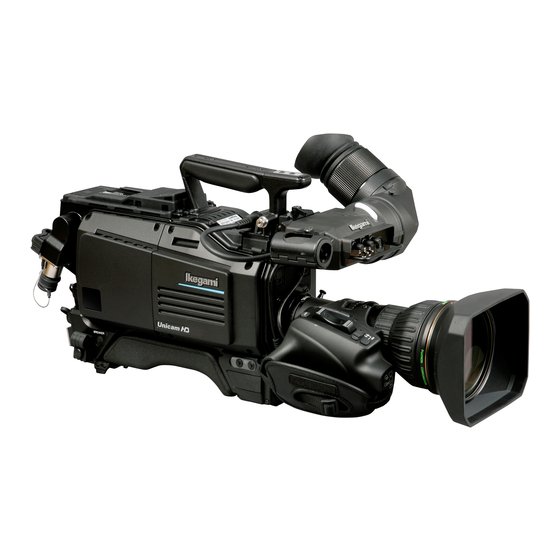
- Page 1 ACTIVE STANDBY BS/CCU POWER HDK-73 ( FA-55 ) HIGH DEFINITION CAMERA SYSTEM OPERATION MANUAL...
- Page 3 OUTLINE HDK-73 NAME and FUNCTION ( FA-55 ) INSTALLATION and CONNECTION HIGH DEFINITION CAMERA SYSTEM OPERATION OPERATION MANUAL CAMERA SETTINGS and ADJUSTMENT TROUBLE SHOOTING and MAINTENANCE SPECIFICATIONS CHANGING INFORMATION 1707 1st Edition (E)
- Page 4 Copyright © 2012 Ikegami Tsushinki Co., Ltd. We reserve the copyright on the software we create. Ikegami Tsushinki Co., Ltd.
-
Page 5: Products Conforming To Rohs Directive
80% and less than 85% by weight 14. Lead in solders to complete a viable electrical connection between semiconductor die and carrier within integrated circuit Flip Chip packages 15. Decabrominated diphenyl ether (Deca-BDE) in polymeric applications HDK-73 1707 VER1 (E) -
Page 6: Maintenance Of Products Conforming To Rohs Directive
· If the customer mixed the lead-solder with the main body wiring or the circuit board, it becomes guarantee off the subject. Ikegami doesn't guarantee to do the repair work. Because the solder polluted with lead cannot be removed. 3. Parts Be sure to use parts conforming to RoHS directive. -
Page 7: Information To The User
Marking Styles for Names and Contents of Toxic or hazardous Substances and Elements Hexavalent Polybrominated Polybrominated Part Name Lead Mercury Cadmium Chromium biphenyls diphenyl ethers (Pb) (Hg) (Cd) (Cr/(VI)) (PBB) (PBDE) HDK-73 × requirement in SJ/T11363-2006. above the limit requirement in SJ/T11363-2006. HDK-73 1707 VER1 (E) -
Page 8: Safety Precautions
Mishandling may not directly lead to death, injury, or property damage. Indicates that mishandling may cause an electric shock. Indicates that mishandling may cause injury. The following symbol is used to indicate other precautions to prevent damage or hazard from occurring: Indicates prohibited action. HDK-73 1707 VER1 (E) - Page 9 ■ Handling Precautions Regarding the Product Do not disassemble or modify the product which is not described in this manual. Doing so may Regarding the Power or electric shock due to a damaged cable. To inspect or operate on the inside of the equipment, turn off the power and wait for one or two minutes before starting work.
- Page 10 Use the product in compliance with the rating of the fuse within the product and that within the Camera Control Unit (BS). Otherwise, a fault can occur. When changing or discarding a battery, please contact Ikegami's sales and service centers. Risk of explosion if battery is replaced by an incorrect type. Dispose of used batteries according to the instructions.
- Page 11 Regarding the Fiber Connector and the Fiber Optic Cable connector (plug) and not the cable. - Do not crush the cable. - Since there can be various obstacles (such as a corner of a building, glass, rough ground surface) in places where the cable is connected, do not drag the cable without winding. Radius Approx.
- Page 12 This product includes parts that wear out and have a limited life even in proper use or storage. Therefore, regular maintenance is recommended to extend the life and safe use of this product for a long time. Please contact Ikegami's sales and service centers for the regular maintenance and repair of our products.
-
Page 13: How To Read The Operation Manual
TO RE D THE OPER TION M NU HOW TO READ THE OPERATION MANUAL This page explains general notes on reading the HDK-73 Operation Manual, and the symbols and notations used in the manual. ■ Notes on the Manual - This manual is written for readers with a basic knowledge of handling broadcast cameras. - Page 14 When the alarm lamp lights during the operation of this product, read here to know the problem. This chapter also explains the regular maintenance such as cleaning of connectors and resetting of breaker. SPECIFICATIONS Chapter 7 CHANGING INFORMATION HDK-73 1707 VER1 (E)
-
Page 15: Table Of Contents
Connection Examples for Each Allocating Functions to the P.FUNC Switch . . 76 Operating System ....33 HDK-73 1707 VER1 (E) - Page 16 Sensor defect correction ....116 Chapter 7. SPECIFICATIONS HDK-73 Specifications ....119 External Dimensions Diagram ...121 External Connections .
-
Page 17: Chapter 1. Outline
OUTLINE... -
Page 19: Features Of This Product
■ HDK-73 possible to create images from natural and delicate to bold and colorful with image effects meeting the producer’s requirements. The image for VF (View Finder) is equipped with a new image processing circuit (focus assist function) and supports the focusing operation of the camera operator. -
Page 20: Pursuit For Superb Operation And Ease Of Use
Pursuit for Superb Operation and Ease of Use ■ ■ ■ ■ Rotating Camera Cable Connection ■ ■ Peripheral Equipment Supporting a Wide Range of Applications Note: Equipped with Various Interfaces Reference: i i i i Support Function for Camera Setup... -
Page 21: Operating Systems
1.2 Operating Systems Term: OCP (Operation Control This product is equipped with functions which interface with a control panel and a control Panel) unit. If you use the BSF-55, this product can support not only stand-alone VTR shooting but This control panel is used for normal operation. - Page 22 ■ Camera Head PM WFM BS-1 CONT BS-1 COMM WFM, COMM CSU-1 BS-8 BS-8 PM, WFM, COMM CSU- BS-1 BS-1 BS-1 BS-1 CSU- CSU- ■ Camera Head ECORDER...
- Page 23 PM WFM erm: BS-1 It is designed as the HUB Serial communication cable unit which employs command CP cable converter for Ikegami's non- network capable camera head/ BS/CCU to use under network BSH- control system. Ethernet cable Note: - The OCP/CCP connector and...
-
Page 25: Connection Diagram
2 2 ... -
Page 27: Chapter 2. Name And Function
NAME and FUNCTION... -
Page 29: Camera And Viewfinder
2.1 Camera and Viewfinder Camera Right View ○RET-1 button RET-2/MIC button○ Handle○ ○Viewfinder(VF) Shoulder belt hook○ INTERCOM PHONE○ control knob INTERCOM PGM○ control knob INTERCOM MIC button○ ST N B BS CCU POWER Switch control panel cover○ Shoulder pad○ POWER switch○ POWER indicator○... -
Page 30: Intercom Mic Button
① Viewfinder (VF) ② Handle Reference: The functions are allocated ③ RET-2/MIC button using the menu. Refer to The RET-2 switch function or INTERCOM MIC switch function is allocated to this button. "5. CAMERA SETTINGS The button selects the function or turns ON/OFF the function. and ADJUSTMENT [Menu ● When set to RET-2 Configuration and content]"... -
Page 31: Shutt/Sup-V Switch
⑬ SHUTT/SUP-V switch Switches between the shutter speed and Super V function. The function working is Reference: The shutter speed is set from the menu. Refer to "5. CAMERA SETTINGS and ⑭ FILTER HEAD switch ADJUSTMENT [Selecting Shutter Speed]" (P72) for setting. -
Page 32: Gain Select Switch
⑳ OUTPUT SELECT switch Note: the Output Select defaults to Switches between the picture shot by the camera and the color-bar signal. the OCP in system GAIN SELECT switch ○ Note: Selects the gain of the camera. with the BSF-55. -
Page 33: Camera Left View
Camera Left View Shoulder belt hook○ VF connector○ VF CONNECTOR LOCK button○ ○CAMERA CABLE clamp ○MIC CABLE clamp BREAKER RET-1 button○ ○Breaker Memory Card Slot○ ○CAMERA connector RET-2/MIC button○ VF CABLE clamp○... -
Page 34: Shoulder Belt Hook
① Shoulder belt hook ② VF connector Connects the VF cable ③ VF CONNECTOR LOCK button Prevents the VF connector from being disconnected. To disconnect the VF cable, hold down this button. ④ VF CABLE clamp Secures the VF cable. ⑤... -
Page 35: Camera Front View
Camera Front View ○LENS LOCK lever ○Lens mount P FUNC PUSH M NU ○Cable clamp ○P.FUNC switch ○VF CHAR button LENS connector○ P FUNC ○ROTARY PULSE switch PUSH M NU MIC button○ ○SET button... - Page 36 ① Lens mount Various 2/3" broadcast HD lenses can be mounted. ② LENS LOCK lever Locks the lens mount. Turn the lens mount ring using this lever to secure the lens after the lens is inserted into the lens mount. ③...
-
Page 37: Camera Rear View
Camera Rear View RET-2 SELECT switch○ ○INTERCOM FRONT VR SELECT switch GREEN TALLY indicator○ ○RET-1 SELECT switch REAR TALLY switch○ ○RED TALLY indicator INTERCOM-1 control knob○ ○CALL button INTERCOM-1 PGM1 control knob○ ○INTERCOM-2 control knob INTERCOM-1 MIC switch○ ○INTERCOM-2 PGM1 control knob INTERCOM-1 PGM2 control knob○... - Page 38 ① GREEN TALLY indicator ights when the signal is input to the BS. ② RED TALLY indicator ights when the signal is input to the BS. It also lights when the C button on the BS or control panel is pressed. ③...
-
Page 39: Power Switch
⑮ DC IN connector ⑯ AUX OUT connector Outputs the Q-TV and VBS signals. Select the Q-TV and VBS signals from the camera menu screen. The Q-TV signal output function only responds during BS operation. ⑰ MIC-2 connector Connects a microphone or input audio signal of line level. ⑱... - Page 40 INTERCOM-1 MIC switch ○ Turns ON/OFF the INTERCOM-1 intercom microphone. RET-1 SELECT switch ○ Selects the input connected at the base station as the RET-1 signal sent to the camera. RET-2 SELECT switch ○ Selects the input connected at the base station as the RET-2 signal sent to the camera. MON SDI connector ○...
-
Page 41: Viewfinder (Vfl200Hd)
Viewfinder (VFL200HD) ○REAR TALLY Lamp Diopter Adjustment lever○ (with switch) ○VF cable ○EYEPIECE Release lever ○MIC HOLDER attaching mount ○PEAKING knob ○CONTRAST knob ○BRIGHTNESS knob Escutcheon ○FRONT TALLY Lamp label display ○MENU knob ○ASSIGNABLE switch F1, F2, F3... - Page 42 ① VF cable ② EYEPIECE Release lever ③ Diopter Adjustment lever arning: ④ PEAKING knob ⑤ CONTRAST knob ⑥ BRIGHTNESS knob ⑦ ASSIGNABLE switch F1, F2, F3 ⑧ MENU knob ⑨ FRONT TALLY Lamp ⑩ REAR TALLY Lamp (with switch) ⑪...
-
Page 43: Displays In The Viewfinder
2.2 Displays in the Viewfinder provided below. LED Indicator the set value. BATT standard. (Refer to Note.) Note: The ! indicator lights when the following settings are made. Switch/Function Setting Status AWB SELECT switch KNEE MODE MANUAL SKIN DTL SHUTTER A. -
Page 44: Side Mask Function
Side Mask Function hen the camera output aspect ratio is set to the picture Reference: Brightness of the picture outside the frame marker can be ad usted. Display Mode Reference: Viewfinder Display ■ tat ⑦ Fan status ① Memory backup battery voltage MEM BAT WARN... - Page 45 ■ Warning Display ⑬ Temperature warning TEMP!! ■ Auto Setup Display ② Auto setup function ABB ⑤ Execution result of auto setup O K BLKSET ⑥ Adjustment item of auto setup ■ Return Video Channel Display ⑱ Return video input channel RET−1...
- Page 46 ① Memory backup battery voltage ⑪ BARS TITLE The warning message is displayed until the power is turned off The bar title is displayed when the color bar is output. when the voltage of the backup battery in the MPU module has dropped.
-
Page 47: Installation And Connection
INSTALLATION and CONNECTION... -
Page 49: Preparation
Connection Example for Each Operating System Not only can the HDK-73 be used stand-alone for video location operation, but it can also be used in various operating systems in This section shows a connection example of each operating system. Please refer to these examples when you connect the camera,... - Page 51 2 ...
- Page 53 2 ...
-
Page 55: Camera And Peripheral Installation And Connection
3.2 Camera and Peripheral Installation and Connection Mounting/Removing the Camera on/from the Tripod ■ Mounting the Camera on the Tripod applications and purposes. For details on the tripod, refer to the instructions accompanying the tripod to be used. Mounting on a VIDEO-18 will be described below as an example. - Page 56 After inserting the front wedge of the camera, tighten the lock lever until the camera is completely fixed. Red button sound when the lock lever is locked. Make sure that the camera is fixed to the tripod Lock lever mount plate completely and does not wobble. ⑤...
-
Page 57: Mounting And Removing The Lens
Mounting and Removing the Lens ■ Mounting the Lens This section explains how to mount the lens to the camera. Before proceeding any further, remove the lens cap by pushing up the lens lock lever. Align the pin of the lens with the notch of the camera lens mount, and horizontally insert the lens into the camera lens mount. - Page 58 ■ Removing the Lens This section explains how to remove the lens. Disconnect the pigtail cable from the lens connector. Hold the connector of the pigtail cable and pull at the locking ring to unlock and release it from the lens connector.
-
Page 59: Mounting And Removing The Viewfinder
Mounting and Removing the Viewfinder ■ Mounting the Viewfinder Make sure the camera power switch is OFF. If the power switch is set to BS or EXT, turn it OFF. ② Tilt the eyepiece Tilt the viewfinder eyepiece upward 90 degrees. upward degrees. - Page 60 Adjust the viewfinder position. ● A djust the left and right positions of the e e e e e a ● viewfinder Turn the left-right lock lever on the camera ゚ ゚ ゚ lock. ● A djust the front and back positions of the viewfinder Loosen the front-back lock lever on the camera to forth to the desired position and lock.
-
Page 61: Attaching A Microphone
Attaching a Microphone This camera is equipped with two microphone channels (MIC-1 and MIC-2). Please select depending on the operation. This section Note: The microphone holder is optional. S re Make sure the microphone holder is attached to the viewfinder. If the microphone holder is not attached, attach it to the Loosen the screw on the microphone holder to Camera r... -
Page 62: Connecting A Headset
Connecting a Headset Two intercom headsets (1 and 2) can be connected to the HDK-73. Please select the headset connector depending on the use. This section explains how to connect using the Intercom 1 headset connector. Camera rear Plug the headset connector into the INTERCOM-1 connector on the camera. -
Page 63: Power Connection
3.3 Power Connection system. ● To supply from an AC Adapter (External power) more). ● To supply from the BS Note: Make sure that the camera POWER switch is OFF before connecting the power. Refer to "Make Sure the Power Switch is OFF" (P33) for how to check the power. -
Page 64: Power Supply From Bs
Power Supply from BS Explains how to supply power from the BSF-55. C INPUT BSF- rear F er a e e amera C a e Make sure the BSF-55 MAIN POWER switch is OFF. Connect the AC cable to the AC INPUT connector on the rear of BSF-55. Insert the AC plug into the power outlet. - Page 65 To Control Power ON/OFF from BS ■ Set the BS MAIN POWER switch on the front of the BS to "ON". connection between the camera and the BS is automatically checked. When the connection status is determined as normal, BS M IN POW d a r BSF- d a r...
- Page 66 To Control Power ON/OFF from OCP (Remote Control) ■ Set the BS MAIN POWER switch on the front of the BS to "ON". Set the CAM POWER switch on the OCP to "ON". Power is supplied to the camera. C M PW OCP- Note: power is not turned "ON/OFF".
-
Page 67: Monitor Connection
3.4 Monitor Connection This section explains how to connect the HDK-73 to monitors. Connecting Camera and Monitor There are three connectors on the rear of the camera to output various video signals. The type of video signal output from each connector is different. -
Page 68: Bs Connection
3.5 BS Connection This section explains how to connect the HDK-73 to the BS. BSF-55 as an example. Connecting Camera and BS Camera rear INCOM INCOM F er a e BSF- rear Connect the CAMERA connector on the rear of the BSF-55 to the CAMERA connector on the rear of the camera via a fiber cable. - Page 69 ■ Remo ing t e iber Cable C UTION en o remo e t e cable be re to ol t e l g an ail re to o o ma amage Camera ● Camera rear ma e INCOM INCOM ema e F er a e ●...
-
Page 71: Chapter 4. Operation
OPERATION... -
Page 73: Operating Procedures
4.1 Operating Procedures This chapter e plains how to operate this product.. Initial Operation Check ■ ―――――――――――――― ◆ ◆ ◆ Preparation Before Shooting ■ ――――――――――――――――― ◆ ◆ ◆ Shooting Settings and Adjustment ■ ―――――――――――――――――――― camera is used. ◆ ◆... -
Page 74: Switch Position Check
4.2 Switch Position Check camera is used and shooting conditions. Camera Right ■ CC FI T SHUTT SUP- N FI T Note: IN S When the camera is connected to the BS, the switches on the OUTPUT S WB S camera are disabled except the CC FILTER switch (ECC) and ND FILTER switch. - Page 75 ■ Viewfinder B I HTN SS CONT F ONT T Note: the VF. a e SW1 M NU...
-
Page 76: Turning On Power
4.3 Turning ON Power The procedure for turning the power ON/OFF depends on how power is supplied to the camera. This section explains how to Power Supply from AC Adapter Reference: Refer to "3. INSTALLATION and CONNECTION [Power Supply from AC Adapter]" (P47) for how to connect the camera to the Set the POWER switch on the camera to EXT. - Page 77 Make sure that the ALARM indicator on the OCP or MCP is not flashing will be displayed for 20 seconds. PM IND/PAGE button ALARM indicator Note: ■ To Control Power ON/OFF from OCP It is possible to use the OCP to control the camera power switching. turned ON/OFF.
-
Page 78: Viewfinder Adjustment
4.4 Viewfinder Adjustment environment in which the camera is used. Reference: Refer to "3. INSTALLATION and CONNECTION [Mounting and Removing the Viewfinder]" (P43) for how to adjust the position Diopter Adjustment and Screen Adjustment ■ Diopter Adjustment e e e While pressing the Diopter Adjustment lever, slide in either direction for the best focus. -
Page 79: Output Signal Check
4.5 Output Signal Check reason, check the following before concluding that there is a failure. Reference: Refer to "3. INSTALLATION and CONNECTION" (P31) for connection of peripheral equipment. Color-Bar Signal Check Set the BARS button on the OCP or MCP to ON. Ensure that a normal color-bar signal is output. -
Page 80: Test Pulse (Cal Signal) Check
Test Pulse (CAL Signal) Check Check if the level of the video system is normal. Set the CAL button on the OCP or MCP to ON. Ensure that 100% level of test pulse is output. MONITO S WFM PM Se 1 )... -
Page 81: Auto Setup
■ Auto Setup Screen executing item is indicated by the cursor. the cursor on the failed item. a S ree *** AUTO SETUP MONITOR *** [HDK-73] Function: AUTO BLACK SHADING Mode: Lens No.1 Chart: EXT. Judgement: Setting Position: H V... -
Page 82: Auto White Balance
Auto White Balance Use the AWB SELECT switch to select the memory (Ach or Bch) in which to store the execution result. selectively depending on different conditions. when the switch is set to this position. ① Use the CT switch Note: to select the memory. -
Page 83: Auto Black Balance
Auto Black Balance Set the AWB/ABB switch to ABB. The lens iris is automatically closed, and auto black balance is now activated. ① Set the B/ BB switch to BB. Check the result. ABB CAUTION: BLK SET position before activating the auto black balance from the camera. -
Page 84: Preparation For Shooting In Particular Environments
4.7 Preparation for Shooting in Particular Environment When the camera is used in a particular environment such as where the temperature is extremely low, where the camera is subject necessary to take the following protective measures for proper operation of the camera. ■... -
Page 85: Chapter 5. Camera Settings And Adjustment
CAMERA SETTINGS and ADJUSTMENT... -
Page 87: Settings Using Switches On The Camera
5.1 Settings Using Switches on the Camera Adjusting Headset Volume This chapter explains how to control the headset volume. CAUTION: your ears may damage your eardrums. If you suddenly set the volume level too high, it may also damage the headset. Excessive sound pressure from the headset may cause a hearing loss. -
Page 88: Selecting Shutter Speed
■ Adjusting Intercom PGM Volume on the rear of the camera, and Steps 1, 3, and 4 to control on the right side of the camera. Use the INTERCOM-1 PGM-1/2 switch or INTERCOM-2 PGM-1/2 switch on the rear of the camera to select an intercom PGM line. - Page 89 Select "1" or "2" from MENU (1/4) "VF DISPLAY" - "DISPLAY MODE." Reference: Refer to "5.2 Settings from the Menu [Menu Configuration and content]" (P81) for how to display characters in the Set the SHUTT/SUP-V switch on the right side of the camera to SET. - Preset shutter speed - Variable shutter speed - SUPER-V...
-
Page 90: Enhancing The Vertical Resolution (Super-V Function)
Enhancing the Vertical Resolution (Super-V Function) Super-V function enhances the vertical resolution. It is activated from the camera, MCP, or OCP. Note: - The sensitivity of the camera decreases when in the Super-V function mode. - When a remote controller is connected, the operation of the remote controller has priority over the operation switches on the camera. Camera r Camera r SHUTT SUP-... -
Page 91: Switching The Gain
Switching the GAIN When using the camera under the conditions such as evening,, night time, or indoor use, the gain (sensitivity) of the camera needs to be adjusted to suit the brightness of the subject. The gain can be adjusted on the camera or from the remote controller. ■... -
Page 92: Allocating Functions To The P.func Switch
Allocating Functions to the P.FUNC Switch The user can select a function to allocate to the P.FUNC (Personal Function) switch. By allocating the function used most frequently, the user can easily operate the camera. Camera r P FUNC Set the P.FUNC switch on the front of the camera to SEL. -
Page 93: Screen Detail Enhancement (Dtl)
Screen Detail Enhancement (DTL) Term: Skin DTL Skin DTL function suppresses the amount of the edge signals in the skin colored area, while maintaining the DTL setting for the entire picture. To achieve the best effect, it is important to ensure that the skin DTL function does not affect the clothing and colors appearing immediately next to the skin colors. -
Page 94: Settings From The Menu
5.2 Settings from the Menu Basic Operation of the Menu monitor. Camera r F CH Rotary pulse switch SET button VF CHAR button ■ Displaying the Simple Menu Press the SET button while holding down the VF *** MENU *** CHAR button on the front of the camera. VF DISPLAY... - Page 95 ■ Displaying the Main Menu Press and hold the SET button while holding down *** MENU *** the VF CHARA button on the front of the camera. VF DISPLAY VF DTL VF MODE FOCUS ASSIST Simple Menu MIC GAIN CONTROL RETURN SELECT MODE FILTER SERVO MODE SW FUNCTION INFORMATION *** MENU(1/4) *** Shift to menu ▲...
- Page 96 ■ Exiting the Menu Press the VF CHAR button on the front of the camera. The main menu/submenu disappears. Note: The menu screen at the time of SE operation disappears when the MENU switch is set to "OFF".
-
Page 97: Menu Configuration And Content
Menu Configuration and content ■ MENU (Simple Menu) The simple menu is the same as MENU (1/4) described below. Refer to items in MENU (1/4) for details of each menu. ■ MENU (1/4) MENU DATA Initial Menu Item Setting value Description, Remarks setting VF DISPLAY... - Page 98 MENU DATA Menu Item Initial setting Setting value Description, Remarks FOCUS ASSIST ― ASSIST AREA × × with the trigger of lens operation, etc. FOCUS, FOCUS/ ― TRIGGER FOCUS × × selected. LENS VTR, EXT ― AREA ON/OFF SW NONE ×...
- Page 99 MENU DATA Initial Menu Item Setting value Description, Remarks setting SW FUNCTION ― RET-1 (HANDLE) RET-1 ○ × Sets the button control of RET-1 and RET-2/MIC on the top FOCUS-, NONE of the handle. ― RET-2 (HANDLE) RET-2 ○ × NONE ―...
- Page 100 ■ MENU (2/4) MENU DATA Initial Menu Item Setting value Description, Remarks setting VIDEO OUTPUT MODE ― SDI OUT ON, OFF Turns the HD-SD signal (mainline) output ON/OFF. ○ × Switches the signals (HD-SDI) output from the MON SDI OUT connector. ―...
- Page 101 MENU DATA Initial Menu Item Setting value Description, Remarks setting See "5.3 Using the Memory Card" (P100) for the memory MEMORY CARD card usage method. ― SAVE FILE ― ALL DATA ― SNAP SHOT ― SCENE Saves the selected data to the memory card. ―...
- Page 102 ■ MENU (3/4) MENU DATA Initial Menu Item Setting Value Description, Remarks Setting SCAN FORMAT SELECT Selects the camera operation format. Destination 1080I59, 720P59, SCAN MODE * If BS/CCU is connected, the format on the BS/CCU side × × setting 1080I50, 720P50 and the operation format will be the same.
- Page 103 MENU DATA Initial Menu Item Setting Value Description, Remarks Setting LENS SELECT Select the lens file number. -If the lens code is obtained from the lens, (CODE SEL) is ― NUMBER NO.1 to NO.8, OFF displayed on the back of the lens number display. ○...
- Page 104 MENU DATA Initial Menu Item Setting Value Description, Remarks Setting ON, OFF Possible to increase the DTL level of the highlight part. ― HI-LIGHT DTL × × ― GAIN 0 to 100 × × LIMIT × × raises the limit and lowers the DTL level. SMOOTH KNEE is a function to adjust the compression level of the brightness signal with KNEE.
- Page 105 ■ MENU (4/4) MENU DATA Initial Menu Item Setting Value Description, Remarks Setting INCOM SETUP ― RECEIVE ― INCOM1 L/R CH ― INCOM1 BOTH ○ × channel. ― INCOM2 BOTH ○ × channel. ― PGM1 BOTH ○ × channel. ― PGM2 BOTH ○...
- Page 106 ■ ENGINEER (1/2) MENU DATA Initial Menu Item Setting Value Description, Remarks Setting Supplies power from DC connector of adapter when BS/ CCU is connected. In this case, stops power supply from an FIBER SINGLE MODE CONT optical cable. If it is sets to "ON," the mode is switched to the single fiber SINGLE MODE ON, OFF ○...
- Page 107 MENU DATA Initial Menu Item Setting Value Description, Remarks Setting INCOM SETUP (ENG) ― HEADSET ― INCOM1 Selects carbon or dynamic for INCOM microphone. × × Sets the ON/OFF of the power supply to dynamic ― INCOM1 POWER ON, OFF ○...
- Page 108 MENU DATA Initial Menu Item Setting Value Description, Remarks Setting C OSS ― Sets the connection preset setting of I COM line. × × Sets the connection for when US is selected in ― I COM MO S T. C OSS oad the setting that becomes a base of the setting.
- Page 109 ■ ENGINEER (2/2) MENU DATA Initial Menu Item Setting Value Description, Remarks Setting PROCESS ENABLE ― COLOR CORR ○ × ― CUSTOM COL1 ○ × ON/OFF of processing and analog control.) ― CUSTOM COL2 ○ × PROGRAM UPDATE ○ × VF CONT Sets whether the RETURN control signal is sent to VF or not.
- Page 110 ■ FILE SET "LENS SELECT" on MENU (3/4), then "FILE SET". The following explains the set values, descriptions, and setting procedures. Set Value Description OFF (default) Does not create lens files. MANUAL Stores the current lens status as a file. ("LENS No. x" will be displayed at the bottom of the screen.) Starts auto setup for lens file creation.
- Page 111 *** MENU (3/4) *** ▲ SCAN FORMAT SELECT CPU SYSTEM CONTROL AUTO IRIS SET The submenu is displayed. AWB/ABB MODE ③ LENS SELECT LEVEL ADJUST Position the flashing PROCESS MODE cursor on PRESET FILE LOAD CT and confirm. MENU MODE efer to the e planation of corresponding item for how to set each data. O. is selected here as an e ample. LENS SELECT...
- Page 112 Turn the rotary pulse switch to position the cursor LENS SELECT on the AUTO SEL NAME display part (AB40X10 NUMBER NO.1 ABCD), and press the SET button. NAME ( ) M① (AB40X10 ABCD ) The screen switches to a display for obtaining a new EXTENDER OFF Position the cursor on AUTO SEL OFF...
- Page 113 Note: NUMBER OFF NAME ( ) - When the new model name cannot be loaded from the MODEL AUTO READ EXTENDER OFF AUTO SEL OFF of "COMPLETED." FILE SET MANUAL LENS TYPE *** LENS NO.1 hen the new model READ ERROR name cannot be loaded - When the rotary pulse switch is turned to switch the NUMBER OFF...
- Page 114 Turn the rotary pulse switch to position the cursor LENS SELECT on "FILE SET", and press the SET button. NUMBER NO.5 NAME ( ) The cursor moves to the mode selection column. (AB40X10 ABCD ) EXTENDER OFF AUTO SEL OFF E④ FILE SET OFF LENS TYPE *** Position the cursor on AUTO X0.8 CONV ...
- Page 115 Turn the rotary pulse switch to edit the lens AUTO SEL NAME EDIT name. Use "*" for the characters that are not to be AUTO SEL NAME EDIT compared in "AUTO SEL". E⑨⑩ (AB40X10 A*** ) Change the characters not to be compared to "BCD" are not to be compared here as an example. and confirm.
-
Page 116: Using The Memory Card
5.3 Using the Memory Card The memory card can be used to store/read the setting condition of the camera. CAUTION: responsibility for guaranteeing operation. ■ Inserting and removing the memory card There is a memory card slot as shown in the illustration below on the bottom left side of the camera main unit. Open the dustproof cover and insert the memory card in the memory card slot. - Page 117 ■ Storing the camera setting state on the memory card LOCK side. Turn the rotary pulse switch on MENU (2/4), set MEMORY CARD the cursor to [MEMORY CARD] and press the SET SAVE FILE button. LOAD FILE The submenu is displayed. Select [SAVE FILE] and press the SET button. Select the item from the SAVE FILE submenu that you wish to save.
- Page 118 If a file with the same file name exists on the SAVE FILE memory card, a message is displayed asking ALL DATA ABCDEFGH .CDF whether it is okay to write over the data. To enable SNAP SHOT writing over of data, change [NO] to [YES] and SCENE...
- Page 119 ■ Reading the camera setting condition from the memory card. Read the camera setting condition from the memory card. Turn the rotary pulse switch on MENU (2/4) to MEMORY CARD adjust the cursor to [MEMORY CARD] and press S A V E F I L E the SET button.
- Page 120 ■ Error Messages shown below. Error Message Contents NO CARD Memory card not inserted. CANNOT OPEN FILE File cannot be opened. NOT CAMERA DATA FILE. Not a camera data file. FILE OF DIFFERENT CAMERA. Different type of file. RELEVANT DATA IS NOT FOUND. Relevant data cannot be found.
-
Page 121: Chapter 6. Trouble Shooting And Maintenance
TROUBLE SHOOTING and MAINTENANCE... -
Page 123: Alarm Lamp On The Ocp Or Mcp Flashes On And Off
Refer to this chapter when the alarm lamp lights or when you want to know about the maintenance during the use of this product. ■ Problems ■ Questions - How to reset the settings to default (Return to the factory settings) ... -
Page 124: Temp!!" Or "Fan!!" Appears On The Vf Screen
6.2 "TEMP!!" or "FAN!!" Appears on the VF Screen TEMP!! Status Cause Action The camera is exposed to direct sunlight for Put a sunshade cover on the camera to avoid many hours. direct sunlight. TEMP!! flashing The camera is used near some heating appliance. Move the position of the camera or heating appliance. -
Page 125: Initializing The Settings Of This Product
i i i i 6.3 Initializing the Settings of this Product 1. Initializes the camera back to the user setting (ENGINEER SET FILE). conditions. 2. Initializes the camera back to the initial factory setting (FACTORY SET FILE) The following explains the set values, descriptions, and setting procedures. Set Value Description FILE SELECT... - Page 126 i i i i Turn the rotary pulse switch to select the set value, PRESET FILE LOAD and press the SET button. FILE SELECT ENGINEER ⑤ LOAD START START Select the set value and confirm. PUSH SET→START - Selecting ST displays a message at at the bottom of the screen. the bottom of the screen.
-
Page 127: Cleaning Camera Connectors
6.4 Cleaning Camera Connectors Camera Connector Joint Section ● OPS Ser e SMPT ee e ee e Pre e ema e S re r ma e Ferr e Ferr e Ferr e Pre e ema e Pre e ema e ee e Ferr e Ferr e... - Page 128 Clean the four sections receptacle male on the camera head receptacle female on the BS and plugs male and female on both erie Connector ■ Camera ema e F er a e fter turned or turns counterclockwise the screw ① Turn the screw counterclockwise.
- Page 129 SMPTE type Connectors ■ as an example. CAUTION: When removing the alignment sleeve, be sure to use a dedicated optical contact extractor Prepare a dedicated extractor and place the extractor in a position parallel to the connector. Remove the cap of section A (with a thread). ②...
- Page 130 Insert the alignment sleeve into the optical contact until it clicks and turn the extractor counterclockwise 8 to 10 turns. The extractor is removed from the alignment sleeve. Camera male connectors have neither "top" nor "alignment sleeve" regardless of whether they are receptacles or plugs. For male connectors, therefore, steps 1 to 3 and 8 above are not required.
-
Page 131: Reset The Breaker
6.5 Reset the Breaker If power is not being supplied to the camera even though the power is on and peripherals are connected correctly, it might mean Check that the camera's POWER switch is OFF. Push in the breaker on the left side of the camera. Breaker... -
Page 132: Sensor Defect Correction
6.6 Sensor defect correction Pixel Correct) process. This is effective for small defective pixels (singular pixels). - Page 133 SPECIFICATIONS...
-
Page 135: Specifications
HDK-73 Specifications Ratings ■ Item Rating Remarks 1080i/59.94, 720p/59.94 1 Scanning system 1080i/50, 720p/50 2 Image sensor 2/3 type MOS sensor × 3 Total pixels 2.6M Effective number of 1920 (H)×1080 (V) pixels F12 1080i / 59.94 4 Sensitivity F13 1080i/50 (Calculated value) and from this value, 1080i/50 is calculated. - Page 136 ■ t ignal Item Rating Remarks Pb Pr digital serial optical connector ■ t ignal Item Rating Remarks ‐ Camera cable ■ Item Rating Remarks control cables ■ licable tan ar...
-
Page 137: External Dimensions Diagram
7.2 External Dimensions Diagram Right View ■ ±5 ±1... - Page 138 Left View ■ ±3 ±1 ±5...
- Page 139 Front View ■ P FUNC PUSH M NU ±3 138.5...
- Page 140 Rear View ■ INCOM INCOM ±3 138.5...
-
Page 141: External Connections
7.3 External Connections Lens Connector ■ Used to connect each type of lens. The connector pin assignment differs among camera lens mount types. e e a e Camera ead -1 SC Ca e -1 P-1 PC 1 ma e S de BT M O O /O signal... - Page 142 I IS MOT / UTO switching k or less IRIS REM/AUTO or less ⑧ . k or less k or more k or less Input and output of signal sent from an e ternal system EXT ANS or less . k or less ⑨...
- Page 143 VF Connector ■ e e a e 1 2 3 4 5 6 7 8 9 10 11 12 13 14 15 16 17 18 19 20 Camera ead H 1 -1 S de + 12 V ① + 12 V ②...
- Page 144 CAMERA Connector ■ Used to connect the camera to its BS. [SMPTE type] [OPS Series] e e a e e e a e de mar de mar S de S de SMPT OPS Ser e Camera ead e r d Camera ead de OPS- Ca e...
- Page 145 ■ Connector an Connector Used to connect an intercom headset. ach headset type has each connector shape. ou can use the carbon type of intercom microphone or the dynamic type of that. or switch between the carbon type and the dynamic type use menu display. efer to e e a e Camera ead NC F -...
- Page 146 [5-pin Type] e e a e Camera ead NC F -1 Ne r Ca e - -1 C ma e S de TALK (C) Shield for intercom microphone input C ① TALK (H) Intercom microphone input H Intercom microphone ② SHIELD Shield for IST / IST...
- Page 147 ■ e e a e Camera ead H 1 P M- S ard H S Ca e - -1 C ma e S de MIC (SHIELD) MIC input shield ① MIC HOT line balanced input MIC (HOT) ② hen B power is supplied phantom power is supplied MIC CO line...
- Page 148 REMOTE Connector ■ Used to connect an external remote controller. e e a e Camera ead - 8F Ca e -PB8M 8- ma e S de igital data output from camera to remote HED (+) ○ controller igital data output - from camera to remote HED (-) ○...
- Page 149 Connector for system addition ■ Used to add a system such as SE-H700. e e a e 3 ... 15 18 19 ... . . 32 Camera ead 34 35 36 .
- Page 150 Pin No. Name Function External Interface N . C (Unusable) ○ N . C (Unusable) ○ ○ Write pulse for parallel-serial signal conversion PS WR ○ AD CS 1 Control signal for analog-digital signal conversion ○ AD DATA ○ PWR REQ ○...
- Page 151 Pin No. Name Function External Interface LENS IRIS control output in SE operation IRIS FOLLOW SE ○ (2.1 V to 2.9 V) ZOOM FOLLOW SE ○ (Unusable) N . C ○ N . C (Unusable) ○ N . C (Unusable) ○...
- Page 152 ■ Connector e e a e Camera ead -1 SC Ca e -1 P-1 PC S de igital data input from remote controller to PC RXD (+) ① camera PC RXD (-) igital data input - from remote controller to camera ②...
-
Page 153: Scene File
7.4 Scene File Save condition of a HDK-73 scene file ■ Item Save Data OFF/0.35/0.40/0.45 SMOOTH KNEE SUPER KNEE WHITE CLIP ECC FILTER 3200K/4300K/6300K/8200K ND FILTER ND1 to ND4 SOFT DTL SKIN DTL FINE COLOR DTL COLOR CORRECT COLOR HUE... -
Page 155: Changing Information
CHANGING INFORMATION done by Ikegami. Read by comparing this information with the main part of the operation manual. - Page 157 HIGH DEFINITION CAMERA SYSTEM OPERATION MANUAL 1st Edition : July 2017 Published in Techno Ikegami Co., Ltd. © July 2017 Ikegami Tsushinki Co., Ltd. Ikegami Tsushinki Co., Ltd. of editorial or pictorial content in whole or in part, in any manner, is prohibited.
- Page 160 Ikegami Tsushinki Co., Ltd. 5-6-16, Ikegami, Ohta-ku, Tokyo, 146-8567, Japan Phone : +81-(0)3-5700-4114 Fax : +81-(0)3-5748-2200 E-Mail : info_e@ikegami.co.jp : http://www.ikegami.co.jp/en/ Ikegami Electronics (U.S.A.),Inc. 300 Route 17 South, Mahwah, New Jersey 07430, U.S.A. Phone : +1-201-368-9171 Fax : +1-201-569-1626 E-Mail : engineering@ikegami.com, service@ikegami.com : http://www.ikegami.com...
Need help?
Do you have a question about the HDK-73 and is the answer not in the manual?
Questions and answers