Sign In
Upload
Download
Table of Contents
Contents
Add to my manuals
Delete from my manuals
Share
URL of this page:
HTML Link:
Bookmark this page
Add
Manual will be automatically added to "My Manuals"
Print this page
×
Bookmark added
×
Added to my manuals
Manuals
Brands
Ikegami Manuals
Digital Camera
HDK-99
Operation manual
Ikegami HDK-99 Operation Manual
High definition camera system
Hide thumbs
1
2
3
4
5
6
7
8
9
10
11
12
13
14
Table Of Contents
15
16
17
18
19
20
21
22
23
24
25
26
27
28
29
30
31
32
33
34
35
36
37
38
39
40
41
42
43
44
45
46
47
48
49
50
51
52
53
54
55
56
57
58
59
60
61
62
63
64
65
66
67
68
69
70
71
72
73
74
75
76
77
78
79
80
81
82
83
84
85
86
87
88
89
90
91
92
93
94
95
96
97
98
99
100
101
102
103
104
105
106
107
108
109
110
111
112
113
114
115
116
117
118
119
120
121
122
123
124
125
126
127
128
129
130
131
132
133
134
135
136
137
138
139
140
141
142
143
144
145
146
147
148
149
150
151
152
153
154
155
156
157
158
159
160
161
162
163
164
165
166
page
of
166
Go
/
166
Contents
Table of Contents
Troubleshooting
Bookmarks
Table of Contents
PRODUCTS CONFORMING to Rohs DIRECTIVE
MAINTENANCE of PRODUCTS CONFORMING to Rohs DIRECTIVE
Information to the User
Safety Precautions
How to Read the Operation Manual
Table of Contents
Chapter 1. OUTLINE
Features of this Product
Fusion of High Quality CMOS and Superb Image Processing Techniques
Powerful Support for Various Video Expressions
Pursuit for Superb Operation and Ease of Use
Peripheral Equipment Supporting a Wide Range of Applications
Equipped with Various Interfaces
Support Function for Camera Setup
Operating Systems
Connection Diagram
Chapter 2. NAME and FUNCTION
Camera and Viewfinder
Camera Right View
Camera Left View
Camera Front View
Camera Rear View
Viewfinder (VFL201A)
Displays in the Viewfinder
LED Indicator
Center Marker, Safety Marker, Frame Marker
Zebra Indicator
Side Mask Function
Display Mode
Viewfinder Display
Chapter 3
INSTALLATION and CONNECTION
Preparation
Precaution on Product Use
Make Sure the Power Switch Is off
Connection Example for each Operating System
Camera and Peripheral Installation and Connection
Mounting/Removing the Camera On/From the Tripod
Mounting and Removing the Lens
Mounting and Removing the Viewfinder
Attaching a Microphone
Connecting a Headset
Attaching a Shoulder Belt
Power Connection
Power Supply from AC Adapter
Power Supply from CCU
Monitor Connection
Connecting Camera and Monitor
CCU Connection
Connecting Camera and CCU
Chapter 4. OPERATION
Operating Procedures
Switch Position Check
Turning on Power
Power Supply from AC Adapter
Power Supply from CCU
Viewfinder Adjustment
Diopter Adjustment and Screen Adjustment
Display Mode Check
Output Signal Check
Color-Bar Signal Check
Test Pulse (CAL Signal) Check
External Chart Check
Auto Setup
FULL Auto Setup and LEVEL Auto Setup
FULL QUICK Auto Setup and QUICK Auto Setup
Auto White Balance
Auto Black Balance
Auto Black Shading
Preparation for Shooting in Particular Environment
Chapter 5. CAMERA SETTINGS and ADJUSTMENT
Settings Using Switches on the Camera
Adjusting Headset Volume
Selecting Shutter Speed
Enhancing the Vertical Resolution (Super-V Function)
Switching the GAIN
Allocating Functions to the P.FUNC Switch
Screen Detail Enhancement (DTL)
Settings from the Menu
Basic Operation of the Menu
Menu Configuration and Content
Using the Memory Card
Chapter 6. TROUBLE SHOOTING and MAINTENANCE
Alarm Lamp on the OCP or MCP Flashes on and off
TEMP!!" or "FAN!!" Appears on the VF Screen
Initializing the Settings of this Product
Cleaning Camera Connectors
Reset the Breaker
Sensor Defect Correction
Chapter 7 . SPECIFICATIONS
7.1 HDK-99 Specifications
External Dimensions Diagram
External Connections
Scene File
Changing Information
Advertisement
Quick Links
1
Settings from the Menu
Download this manual
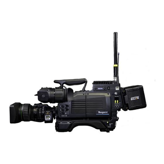
HDK-99
( FA-97A )
HIGH DEFINITION CAMERA SYSTEM
OPERATION MANUAL
Table of
Contents
Previous
Page
Next
Page
1
2
3
4
5
Advertisement
Table of Contents
Need help?
Do you have a question about the HDK-99 and is the answer not in the manual?
Ask a question
Questions and answers
Related Manuals for Ikegami HDK-99
Digital Camera Ikegami HDL-20 Specifications
Full digital small and smart hdtv camera (2 pages)
Digital Camera Ikegami HL-59 Overview
Digital processing camera (6 pages)
Digital Camera Ikegami HDK-970A Specifications
Unicam hd 16-bit full digital 3g hdtv camera system (4 pages)
Digital Camera Ikegami HDL-23 Product Specification
Full digital small and compact 3 cmos hdtv camera (2 pages)
Digital Camera Ikegami HDK-790EXIII Manual
Full digital hdtv companion camera system (25 pages)
Digital Camera Ikegami HDK-79EXII Manual
Full digital hdtv companion camera system (25 pages)
Digital Camera Ikegami HDL-4500 Operation Manual
3cmos super high sensitive hdtv camera (70 pages)
Digital Camera Ikegami HDK-79GX Operation Manual
High definition camera system (158 pages)
Digital Camera Ikegami HDK-73 Operation Manual
High definition camera system (160 pages)
Digital Camera Ikegami HDK-97C Operation Manual
3g high definition camera system (156 pages)
Digital Camera Ikegami HDK-97C Manual
3g high definition camera system (22 pages)
Digital Camera Ikegami ICD-48E Instruction Manual
B/w camera (58 pages)
Digital Camera Ikegami ISD-A35S Instruction Manual
Color camera (50 pages)
Digital Camera Ikegami SKC-141TC Brochure & Specs
Frame shutter monochrome camera (2 pages)
Digital Camera Ikegami MKC-507 Quick Manual
Digital process compact 3ccd color camera (3 pages)
Digital Camera Ikegami ISD-A15 Instruction Manual
Hyper wide dynamic dps camera (52 pages)
This manual is also suitable for:
Fa-97a
Table of Contents
Print
Rename the bookmark
Delete bookmark?
Delete from my manuals?
Login
Sign In
OR
Sign in with Facebook
Sign in with Google
Upload manual
Upload from disk
Upload from URL


Need help?
Do you have a question about the HDK-99 and is the answer not in the manual?
Questions and answers