
Related Manuals for Grizzly G0644


Summary of Contents for Grizzly G0644
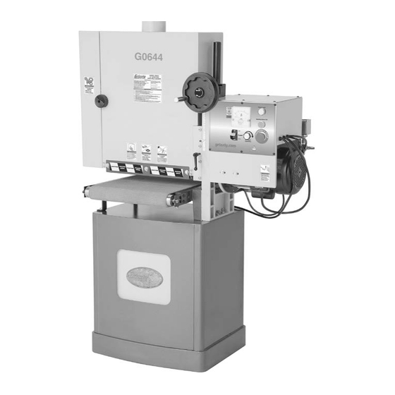
- Page 1 MODEL G0644 15" OPEN-END WIDE BELT SANDER OWNER'S MANUAL WARNING: NO PORTION OF THIS MANUAL MAY BE REPRODUCED IN ANY SHAPE OR FORM WITHOUT THE WRITTEN APPROVAL OF GRIZZLY INDUSTRIAL, INC.
-
Page 3: Table Of Contents
Table of Contents INTRODUCTION ..........2 SECTION 5: ACCESSORIES ......26 SECTION 6: MAINTENANCE ......27 SECTION 7: SERVICE ........29 SECTION 1: SAFETY ........7 SECTION 2: CIRCUIT REQUIREMENTS ..10 SECTION 3: SETUP ........11 SECTION 4: OPERATIONS ......19 WARRANTY AND RETURNS ...... -
Page 4: Introduction
INTRODUCTION Manual Accuracy Contact Info your machine may not exactly match the manual Machine Description www.grizzly.com... -
Page 5: Basic Identification
If you have never used this type of machine or equipment before, WE STRONGLY RECOMMEND that you read books, trade magazines, or get formal training before beginning any projects. Regardless of the content in this section, Grizzly Industrial will not be held liable for accidents caused by lack of training. -
Page 6: Operation Control Identification
Operation Control Identification Figure 2. -
Page 7: Machine Data Sheet
MACHINE DATA SHEET Customer Service #: (570) 546-9663 · To Order Call: (800) 523-4777 · Fax #: (800) 438-5901 MODEL G0644 15" 3 HP OPEN END WIDE-BELT SANDER Product Dimensions: Weight................................418 lbs. Length/Width/Height........................40 x 24 x 62-1/2 in. - Page 8 Conveyor Feed Type........................Direct Current Variable Speed Horsepower............................1/10 HP Voltage..............................220VDC Prewired..............................220VDC Phase................................ Single Amps................................1A Speed..............................10 - 34 RPM Cycle................................60 Hz Number Of Speeds............................1 Power Transfer .............................Gearbox Bearings.......................... Sealed and Lubricated Main Specifications: Operation Information No Of Sanding Heads............................1 Maximum Board Width..........................
-
Page 9: Section 1: Safety
SECTION 1: SAFETY For Your Own Safety, Read Instruction Manual Before Operating this Machine The purpose of safety symbols is to attract your attention to possible hazardous conditions. This manual uses a series of symbols and signal words intended to convey the level of importance of the safety messages. -
Page 10: Safety Instructions For Machinery
Safety Instructions for Machinery 7. ONLY ALLOW TRAINED AND PROP- 16. REMOVE CHUCK KEYS OR ADJUSTING ERLY SUPERVISED PERSONNEL TO TOOLS. OPERATE MACHINERY. 17. DAMAGED MACHINERY. 8. KEEP CHILDREN/VISITORS AWAY. 18. DO NOT FORCE MACHINERY. 9. UNATTENDED OPERATION. 19. SECURE WORKPIECE. 10. -
Page 11: Safety Instructions For Wide Belt Sanders
Safety Instructions for Wide Belt Sanders READ THIS MANUAL. WORKPIECE QUANTITY. KICKBACK. Until you have a clear understanding WORKPIECE INSPECTION. how kickback can occur when using this machine, DO NOT operate this sander! WORKPIECE FEED RATE. BODY PLACEMENT. AVOIDING ENTANGLEMENT. 10. -
Page 12: Section 2: Circuit Requirements
SECTION 2: CIRCUIT REQUIREMENTS Power Connection Device 220V Single-Phase Operation Figure 3 Serious personal injury could occur if you connect the machine to power before com- pleting the setup process. DO NOT connect the machine to the power until instructed later in this manual. -
Page 13: Section 3: Setup
SECTION 3: SETUP Needed for Setup This machine presents serious injury hazards to untrained users. Read through this entire manu- al to become familiar with Description the controls and opera- tions before starting the machine! Wear safety glasses dur- ing the entire setup pro- cess! Unpacking This machine and its com-... -
Page 14: Figure
Inventory Note: If you can't find an item on this list, check the mounting location on the machine or examine the packaging materials carefully. Occasionally we pre-install certain components for shipping purposes. Box 1: (Figure 4) Figure 5. Box 2: (Figure 5) Hardware Bag (Not Shown) SUFFOCATION HAZARD! Immediately discard all plas-... -
Page 15: Figure
Clean Up Site Considerations Floor Load Machine Data Sheet Page 5 Figure 6 For optimum performance, clean all moving parts or sliding contact surfaces. Placement Location Figure 7 Gasoline and petroleum products have low flash points and can explode or cause fire if used to clean machinery. - Page 16 Moving & Assembling Sander The Model G0644 is a Figure 9 heavy machine. Serious personal injury may occur if safe moving methods are not used. To be safe, get assistance and use power equipment to move the shipping boxes and remove the machine from the boxes.
- Page 17 Note: The source of compressed air must provide a steady supply of clean, dry air at 57 PSI or more, not to exceed 120 PSI. Exceeding 120 PSI may result in unpredict- able operation of the sander and damage to the pneumatic system.
- Page 18 Dust Collection Test Run This sander creates substantial amount of wood dust while operating. Failure to wear a respirator rated for wood dust and use an adequate dust collection system when oper- ating this machine can result in short and long-term respiratory illness.
- Page 19 Figure 15 Note: The sanding motor must be ON before the conveyor can be started. Figure 16 Figure 15. Figure 16. Note: You will hear a metallic "thump" when the sanding belt changes oscillation direction. This noise is normal.
- Page 20 Recommended OFF, Adjustments SERVICE Page 31 Page 32 Page 32 Page Page 34 Page 34 Page 35...
-
Page 21: Section 4: Operations
WE STRONGLY REC- OMMEND that you read books, trade maga- zines, or get formal training before begin- ning any projects. Regardless of the con- tent in this section, Grizzly Industrial will not be held liable for accidents caused by lack of training. -
Page 22: Basic Controls
H. Elevation Lock: Basic Controls Figure 17 Elevation Scale & Pointer: Elevation Handwheel: Choosing Sandpaper Figure 18 Figure 17. A. Amperage Load Chart: Grit Class Usage B. Amperage Load Meter: C. Power Light: Figure 18. D. Sanding Motor ON Button: E. - Page 23 Sanding Belt Replacement To change the sanding belt: Figure 19 Figure 20. Note: Some sanding belts are designed to sand in only one direction and have arrows printed on the inside of the belt to show that direction. The front of the sanding drum sup- port has an arrow pointing up showing the direction the sanding belt will travel when in operation (see Figure 20).
-
Page 24: Conveyor Speed
Conveyor Speed Figure 22 Note: The Model G0644 automatically applies the correct tension to the sanding belt when the tensioning lever is secured on the top catch. The moving sanding belt and roller/drum are an entanglement hazard. To avoid the risk... -
Page 25: Depth Of Cut
Depth of Cut Figure 24 Figure 23 first Figure 24. NOTICE DO NOT VOID THE WARRANTY! Keep the amp load within the green SAFE range. If you operate the sander above 14 amps or in the red WARNING range, capacitor or motor failure may occur and will not be covered under warranty. -
Page 26: Sanding Tips
Sanding Tips Choosing Sandpaper Page 20 DO NOT sand more than one board at a time side-by-side. Minor variations in thickness can cause one board to be propelled at a high speed of rate by the sanding belt and could result in serious personal injury. Sanding Belt Oscillation Rate ACCESSORIES... - Page 27 Figure 26 Steps 1–4 NOTICE The sanding belt oscillation system requires compressed air connected to the machine and adjusted to 57 PSI. Without this com- pressed air, the sander will not operate. Figure 26. To adjust the sanding belt oscillation rate: Figure 26 Note: The farther in towards the center you adjust the hex bolt, the slower the sanding...
-
Page 28: Section 5: Accessories
SECTION 5: ACCESSORIES G8027—1 HP Dust Collector G8982—Shop Fox Roller Table Figure 29. Aluminum Oxide Sanding Belts 16"W x 48"L Figure 27. ® H2845—PRO-STICK Sanding Pad H8739—60 Grit H8740—80 Grit H8741—100 Grit H8742—120 Grit H8743—150 Grit H8744—220 Grit Figure 28. -
Page 29: Section 6: Maintenance
SECTION 6: MAINTENANCE Lubrication Always disconnect power to the machine before performing maintenance. Failure to do this may result in serious person- al injury. Schedule To lubricate the elevation gibs: Daily: Figure 30 Bi-Monthly: Cleaning Figure 30. ACCESSORIES Page 26... - Page 30 To lubricate the elevation gears: Air Regulator/Filter Figure 32 Figure 31 Figure 32. Figure 31.
-
Page 31: Section 7: Service
SECTION 7: SERVICE Troubleshooting Motor & Electrical Page... - Page 32 Motor & Electrical (continued) Sanding Operation SYMPTOM POSSIBLE CAUSE CORRECTIVE ACTION Page 33...
- Page 33 Conveyor Belt Tensioning Note: Make sure the distance of the refer- ence measurement taken in Step 1 is the same on both sides. Note: Do not overtighten the conveyor belt. Your goal is reach an approximate ⁄ " hang- ing gap on the underside of the conveyor belt (see Figure 34) and that the belt no longer slips on the rollers.
- Page 34 Conveyor Belt Gib Adjustment Tracking To adjust the gib: To adjust the conveyor belt tracking: Page 27 Page 31 Figure 35 Figure 33 Note: Tracking changes may take a couple of minutes before they are noticeable. Figure 35. Steps 2 & 3...
- Page 35 To adjust the sanding drum and conveyor par- Sanding Drum & allelism: Conveyor Parallelism Note: Use the measurements you recorded when checking the parallelism in the previous procedure. Figure 36 Figure 36. To check the sanding drum and conveyor par- allelism: Steps 1–4...
- Page 36 Air Pressure Safety Adjusting Depth Of Switch Cut Safety Bar Figure 38 Figure 37 Figure 37. Figure 38. To adjust the depth of cut safety bar to the factory setting: Page 33 Figure 37...
- Page 37 To adjust the height of the pressure rollers: Page 33 Figure 40 Adjusting Pressure Rollers Figure Figure 40. Step 2 Figure 39.
- Page 38 Replacing Conveyor Belt Figure 42 To replace the conveyor belt: Figure 41 Figure 42. Figure 42 Figure 41. NOTICE Take care not to scratch or dent the front conveyor roller as you remove it from the sander. Damage to the conveyor roller could result in premature wear of the conveyor belt.
- Page 39 Figure 44 Figure 43 Note: After loosening the left conveyor roller bracket, the rear conveyor roller assembly is supported by its attachment to the conveyor motor assembly. However, to avoid damaging this roller assembly, DO NOT put unneces- sary strain on it. Figure 44.
- Page 40 Electrical Wiring Overview...
- Page 41 Electrical Box & Control Panel Wiring Diagram COLOR KEY Black Blue White Green L6-20 Plug (as recommended)
-
Page 42: Electrical Components
Electrical Components Figure 46. Page 39 Figure 47. Page 39... - Page 43 Electrical Components Figure 48. Figure 51. Conveyor Motor Figure 49. Figure 52. Air Pressure Safety Switch Electrical Box Electrical Box Air Pressure Brake Solenoid Figure 50. Figure 53.
- Page 44 Air System Diagram...
- Page 45 Parts Breakdown...
-
Page 46: Parts List
Parts List REF PART # DESCRIPTION REF PART # DESCRIPTION P0644001 CONVEYOR TABLE PW04M FLAT WASHER 10MM P0644002 CONVEYOR ROLLER BRACKET LR PLW06M LOCK WASHER 10MM PS16M PHLP HD SCR M8-1.25 X 16 PLN05M LOCK NUT M10-1.5 P6003 BALL BEARING 6003ZZ PSB11 CAP SCREW 5/16-18 X 1-1/4 P0644005... - Page 47 Parts List REF PART # DESCRIPTION REF PART # DESCRIPTION P0644093 TUBE CONNECTOR P0644129 BUFFER PAD P0644094 CONNECTING TUBE P608 BALL BEARING 608ZZ P0644095 4-WAY VALVE PW01M FLAT WASHER 8MM P0644096 AIR INLET 1/4 NPT P0644132 CYLINDER BRACKET P0644097 CONNECTOR PS06M PHLP HD SCR M5-.8 X 20 P0644098...
- Page 48 Label Placement & List REF PART # DESCRIPTION REF PART # DESCRIPTION P0644201 MACHINE ID LABEL P0644208 GRIZZLY NAMEPLATE 9-1/4" X 4-1/2" P0644202 MODEL NUMBER LABEL P0644209 ENTANGLEMENT HAZARD LABEL VERT P0644203 ELEVATION HANDWHEEL LABEL P0644210 EYE/LUNG HAZARD LABEL VERT P0644204 CONTROL PANEL LABEL P0644211...
- Page 49 WARRANTY CARD The following information is given on a voluntary basis. It will be used for marketing purposes to help us develop better products and services. Of course, all information is strictly confidential. Note: We never use names more than 3 times. _____________________________________________________________________ _________________________________________________________________________________ _________________________________________________________________________________...
-
Page 51: Warranty And Returns
WARRANTY AND RETURNS 1 year... - Page 52 ® Buy Direct and Save with Grizzly – Trusted, Proven and a Great Value! ~Since 1983~ Visit Our Website Today For Current Specials! ORDER 24 HOURS A DAY! 1-800-523-4777...
Need help?
Do you have a question about the G0644 and is the answer not in the manual?
Questions and answers