Table of Contents
Advertisement
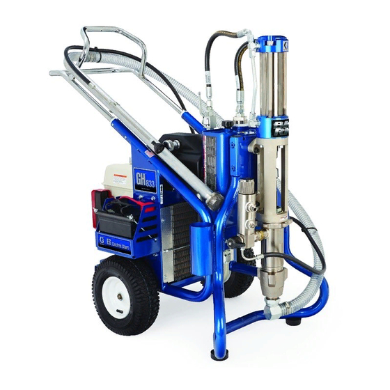
Repair
™
GH
833 Sprayers
Korean patent: 10-0647761
- Use with Architectural Coatings, Paints, Roof Coatings
4000 psi (27.6 MPa, 275.8 bar) Maximum Working Pressure
Important Safety Instructions. Read all
warnings and instructions in this manual. Save
these instructions.
Model: 249318, 249617, 253471, 253472
Related Manuals
311279
311484
311485
311254
Graco Inc. P.O. Box 1441 Minneapolis, MN 55440-1441
Copyright 2006, Graco Inc. is registered to I.S. EN ISO 9001
and Below Grade Coatings -
311283D
ENG
ti7107b
Advertisement
Table of Contents

Subscribe to Our Youtube Channel
Related Manuals for Graco 249318


Summary of Contents for Graco 249318
- Page 1 - Use with Architectural Coatings, Paints, Roof Coatings and Below Grade Coatings - 4000 psi (27.6 MPa, 275.8 bar) Maximum Working Pressure Important Safety Instructions. Read all warnings and instructions in this manual. Save these instructions. Model: 249318, 249617, 253471, 253472 Related Manuals 311279 311484 311485 311254 Graco Inc.
- Page 2 Warning The following are general warning related to the safe setup, use, grounding, maintenance and repair of this equipment. Additional, more specific warnings may be found throughout the body of this manual where applicable. Symbols ap- pearing in the body of the manual refer to these general warnings. When these symbols appear throughout the man- ual, refer back to these pages for a description of the specific hazard.
- Page 3 EQUIPMENT MISUSE HAZARD Misuse can cause death or serious injury. • Do not operate the unit when fatigued or under the influence of drugs or alcohol. • Do not exceed the maximum working pressure or temperature rating of the lowest rated system component.
-
Page 4: Component Identification
Component Identification Description Hydraulic pump valve Pressure control Lock ring Drain valve Engine ON/OFF switch Engine controls Trigger lock Serial number ID label Lift locations Suction holder Hydraulic oil fill Component Identification ti7133 311283D... -
Page 5: Operation
Operation Pressure Relief Procedure System pressure must be manually relieved to prevent it from starting or spraying accidentally. Fluid under high pressure can be injected into the skin and cause serious injury. To reduce risk of injury from injection, follow this procedure whenever you are instructed to relieve pressure, stop spraying, service equipment or install or clean spray tip. -
Page 6: Maintenance
Maintenance For detailed engine maintenance and specifications, refer to separate Honda Engines Owner’s Manual, supplied. Frequency Daily Check engine oil level and fill as necessary. Daily Check hydraulic oil level and fill as necessary. Daily Check hose for wear and damage. Daily Check gun safety for proper operation. -
Page 7: Troubleshooting
PROBLEM Gas engine pulls hard (won't start) Gas engine does not start Gas engine doesn't work properly Gas engine operates, but displace- ment pump doesn't operate Displacement pump operates, but output is low on upstroke Displacement pump operates but output is low on downstroke and/or on both strokes Paint leaks and runs over side of wet- Excessive leakage around hydraulic... - Page 8 PROBLEM The sprayer overheats Spitting from gun Excessive hydraulic pump noise *Check hydraulic fluid level often. Do not allow it to become too low. Use only Graco approved hydraulic fluid, page 6. CAUSE Paint buildup on hydraulic compo- nents Oil level is low Air in fluid pump or hose Loose intake suction Fluid supply is low or empty...
-
Page 9: Displacement Pump Replacement
Displacement Pump Replacement See manual 311485 for pump repair instructions. Removal 1. Flush pump (36). Stop pump on down stroke if possible. 2. Relieve pressure, page 5. 3. Remove suction set (147) from pump (36). 4. Remove filter housing (110), page 15. 311283D 5. -
Page 10: Installation
8. Loosen jam nut (122) with a hammer. Unscrew pump (36) from power head. 9. Remove pump (36). ti7804 Installation 1. Screw jam nut (122) to bottom of pump threads (36). 2. Slide cover (124) up over pump rod. Screw pump completely up into power head. - Page 11 7. Install clip pin (121) to secure. 311283D 8. Install filter housing (110), page 15. ti7809 9. Connect suction hose (147) to pump outlet (36). Displacement Pump Replacement ti7772...
-
Page 12: Pump Power Head Replacement
Pump Power Head Replacement Removal 1. Relieve pressure, page 5. 2. Remove hydraulic lines (100, 101) from head (75). 3. Loosen (4) mounting bolts (7) on the adapter enough to lift and remove assembly. ti7841 4. Remove power head from unit. Installation 1. - Page 13 2. Tighten power head bolts (7). Torque bolts to 400 + 10 in-lb (45 + 1 N•m). 3. Attach hoses (100, 101) to head (75). Torque to 450 + 10 in-lb (50.84 N•m). 4. To purge air from hydraulic lines, increase pressure enough to start hydraulic motor stroking and allow fluid to circulate for 15 seconds.Turn pressure down.
-
Page 14: Hydraulic Motor
Hydraulic Motor 450 in-lb (51 N.m) 600 in-lb (68 N.m) 60 in-lb (7 N.m) 930 in-lb (105 N.m) Torqued in 3 steps Hydraulic Motor ti7868 311283D... -
Page 15: Filter Housing Replacement
Filter Housing Replacement Removal 1. Relieve pressure, page 5. 2. Remove paint and drain lines from filter housing. 3. Loosen filter housing fitting (110) until housing and remove housing from pump. 311283D Installation 1. Install filter housing (110) in pump opening. 2. -
Page 16: Hydraulic Pump Replacement
Hydraulic Pump Replacement Changing Hydraulic Oil Draining Oil a. Place drain pan under oil tank and drain plug. b. Unscrew reservoir (64) drain plug and drain oil from reservoir. Refilling Oil a. Replace drain plug. b. Fill tank with Graco Hydraulic Oil, ISO 46. Tank holds approximately 4 gallons. - Page 17 5. Remove (4) belt cover screws (79), washers (78) and grommets (80) (2 each side). 6. Remove belt cover (67). ti7795 311283D 7. Remove belt (19), page 20. 8. Loosen set-screws (87) on front of large pulley (4). ti7796 9. Remove pulley (4) from hydraulic pump shaft. 10.
- Page 18 11. Remove hydraulic pump (3). 12. Remove fittings (30, 34, 35) from pump (3) and set aside to use on the new pump. Installation 1. Install fittings (30, 34, 35) from old pump on new pump. Torque fitting 30 and 35 to 600 + 10 in-lb (67.8 N.m).
- Page 19 6. Replace set-screws (87). Tighten and torque to 60 + 2 in-lb (6.8 + 0.2 N•m). NOTE: Tighten set-screw on shaft before tightening set-screw on pump shaft. 7. Position belt (19) over pulleys (4, 6); Installing Belt, page 20. 8. Replace belt cover (67) and grommets (80), wash- ers (78) and screws (79), (2 each side).
-
Page 20: Belt Removal And Replacement (Recommended Method)
Belt Removal and Replacement (recommended method) Removing Belt a. Place a ziptie around belt (19). ziptie ti7843 Moving parts can pinch or amputate fingers and other body parts. To avoid serious injury be sure engine is in OFF position before pulling engine recoil. b. -
Page 21: Alternate Belt Removal And Installation
Alternate Belt Removal and Installation Removing Belt a. Loosen engine bolts (21) to relieve tension on belt. b. Slide belt off pulleys. Installing Belt a. Install belt (19) over small (6) and large (4) pulleys. 311283D b. Tighten engine bolts (21). Torque to 225 + 10 in-lb (25.4 + 1.1 N.m). -
Page 22: Replacing Oil Reservoir
Replacing Oil Reservoir Removal 1. Relieve pressure, page 5. 2. Drain oil from reservoir (64) following Draining Oil procedure, page 16. Keep plug for use on new res- ervoir. 3. Remove fill cap (27) and filter assembly (111). Keep for use on new reservoir. 7. - Page 23 ti7791 8. Remove (2) top bolts (86) and 2 bottom nuts (84) securing reservoir (64) to frame. ti7846 ti7786 311283D Hydraulic Pump Replacement 9. Lift reservoir (64) out of frame. Installation 1. Install plug (102), return elbow (31), suction fitting (32), inlet screen (89) and filter assembly (111) in new reservoir (64).
- Page 24 2. Install new reservoir (64) in frame. 3. Replace bolts (86) and nuts (84). Tighten bolts. Torque to 125 + 10 in-lb 14 + 1.1 N•m). 4. Connect coolant line to reservoir (64). Torque to 225 in-lb (14.1 N.m). ti7766 5.
- Page 25 7. Verify drain plug has been replaced. Fill oil reservoir with oil to high mark on dip stick (approximately 3.5 gallons). 8. Replace cap (27). 311283D ti7784 Drain Plug ti7785 Hydraulic Pump Replacement...
-
Page 26: Changing Hydraulic Fluid Filter
Changing Hydraulic Fluid Filter Removal 1. Relieve pressure, page 5. 2. Loosen and remove hose (101) from fitting (103). 3. Remove filter housing (111) from reservoir (64). 4. Remove bottom filer cap (155) from housing (111). 5. Pull filter (108) off cap (155). Installation 1. -
Page 27: Cooler Replacement
Cooler Replacement Removal 1. Relieve pressure, page 5. 2. Loosen ground screw and remove ground clamp (95) from sprayer. 3. Loosen and remove return line to oil tank and hydraulic line to cooler. 311283D 4. Remove screws (79), washers (78) and support bar (77) from cooling coil (72). - Page 28 Installation 1. Install new coil (72). Replace support bar (77), washers (78) and screws (79). Tighten screws. 2. Reconnect return line to oil tank and hydraulic line to cooler. Torque to 225 in-lb (25.4 N.m). 3. Replace ground wire (95) and tighten screw. Torque to 25-30 in-lbs (2.8 - 3.4 N.m).
-
Page 29: Motor Replacement
Motor Replacement Removal 1. Relieve pressure, page 5. 2. Remove screws (79) and washers (78) and belt cover (67). 3. Remove belt (19), page 20. 4. Remove screws (21), washers (70) and nuts (10) securing motor (5) to frame. 5. Remove motor (5) from frame. Replacing Motor Fan Removal a. - Page 30 Motor Replacement ti7797 311283D...
-
Page 31: Removing Handle
Removing Handle Fixed Mounting (optional) To prevent damaging the unit when transporting it in a truck or on a trailer, Graco recommends fixed mounting to the vehicle. Repositioning Handle Before you can secure the unit to a truck or trailer bed, you must reposition the handle. -
Page 32: Securing Unit To Vehicle Bed
Securing Unit to Vehicle Bed For fixed mounting, fasten U-bolts over sprayer frame as indicated in the following illustration. 1. Reposition handle, steps 1-5, page 31. U-bolts 2. Place U-bolts over sprayer frame and through holes in vehicle bed. Place a washer and nut over bolt end. -
Page 33: Technical Data
Technical Data Sprayer Hydraulic Pressure psi (bar) Hydraulic Reservoir Capacity Gallon (liters) Motor HP (kW) Maximum Delivery gpm (lpm) Maximum Tip Size • 1 gun • 2 guns • 3 guns • 4 guns • 5 guns • 6 guns Fluid Inlet inches Fluid Outlet inches Dimensions... -
Page 34: Warranty
Graco warrants all equipment referenced in this document which is manufactured by Graco and bearing its name to be free from defects in material and workmanship on the date of sale to the original purchaser for use. With the exception of any special, extended, or limited warranty published by Graco, Graco will, for a period of twelve months from the date of sale, repair or replace any part of the equipment determined by Graco to be defective.
Need help?
Do you have a question about the 249318 and is the answer not in the manual?
Questions and answers