Table of Contents
Advertisement
Instructions - Parts List
AA Series Spray Gun
For air-assisted spraying and finishing of paints and coatings.
Important Safety Instructions:
Read all warnings and instructions in this manual. Save
these instructions.
See page 2 for List of Models and Table of Contents.
Model G40
Graco Inc. P.O. Box 1441 Minneapolis, MN 55440-1441
Copyright 2005, Graco Inc. is registered to I.S. EN ISO 9001
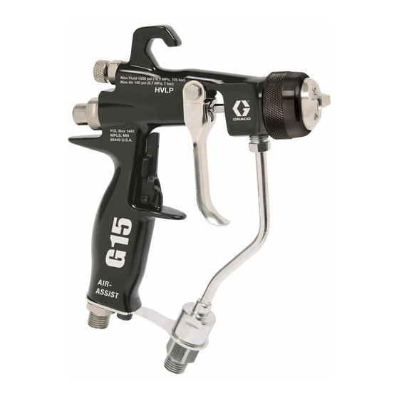
Model G15
TI6844A
TI6553A
Model G40 w/RAC tip
II 2 G
311001F
TI7204B
Advertisement
Table of Contents

Subscribe to Our Youtube Channel
Related Manuals for Graco 288844


Summary of Contents for Graco 288844
- Page 1 See page 2 for List of Models and Table of Contents. Model G15 TI6553A Model G40 Model G40 w/RAC tip TI7204B TI6844A Graco Inc. P.O. Box 1441 Minneapolis, MN 55440-1441 II 2 G Copyright 2005, Graco Inc. is registered to I.S. EN ISO 9001...
-
Page 2: Table Of Contents
Graco Standard Warranty ....36 ® Graco Information ......36 Reverse-A-Clean (RAC) Tip . -
Page 3: Related Manuals
Related Manuals Related Manuals This manual is available in the following languages: Manual Language 311001 English 311145 Chinese 311146 Danish 311147 Dutch 311148 Finnish 311149 French 311150 German 311151 Italian 311152 Japanese 311153 Korean 311154 Norwegian 311155 Polish 311156 Russian 311157 Spanish 311158... -
Page 4: Warnings
Use fluids and solvents that are compatible with equipment wetted parts. See Technical Data in all equipment manuals. Read fluid and solvent manufacturer’s warnings. • Check equipment daily. Repair or replace worn or damaged parts immediately with genuine Graco replacement parts only. •... - Page 5 Warnings WARNING PRESSURIZED ALUMINUM PARTS HAZARD Do not use 1,1,1-trichloroethane, methylene chloride, other halogenated hydrocarbon solvents or fluids containing such solvents in pressurized aluminum equipment. Such use can cause serious chemical reaction and equipment rupture, and result in death, serious injury, and property damage. TOXIC FLUID OR FUMES HAZARD Toxic fluids or fumes can cause serious injury or death if splashed in the eyes or on skin, inhaled, or swallowed.
-
Page 6: Installation
The typical installation shown in F . 1 is only a guide for selecting and installing air-assisted spray systems. Con- tact your Graco distributor for assistance in designing a system to meet your needs. Check your local electrical code and pump manual for detailed grounding instructions. -
Page 7: Air Line
Installation Air Line Fluid Line 1. Install an air filter (A) on the gun air line to ensure a • Before connecting the fluid line, blow it out with air dry, clean air supply to the gun. Dirt and moisture and flush it with solvent. -
Page 8: Setup
See Spray Tip Selection Chart, page 30. Contact your Graco distributor for assistance in selecting an appropri- Model G15 guns (288844) use an air cap alignment pin ate spray tip for your application. to position the air cap. The standard location of the air cap alignment pin is the horizontal air cap position. - Page 9 Setup ® Reverse-A-Clean (RAC) Tip ® Insert the gasket seat. Model 249238 guns use a Reverse-A-Clean (RAC) tip. To assemble the RAC tip, insert the seat housing into the air cap assembly. TI7198A . 10 TI7196A Screw the RAC tip assembly onto the gun and tighten firmly by hand.
-
Page 10: Operation
The card contains important . 12 treatment information should an injection injury occur. Additional cards are available at no charge from Graco. 6. Open all fluid drain valves in the system, having a waste container ready to catch drainage. Leave Pressure Relief Procedure drain valve(s) open until you are ready to spray again. -
Page 11: How The Air-Assisted Spray Gun Operates
Operation How the Air-Assisted Spray Gun 3. Slowly increase the fluid pressure, just to the point where a further increase in fluid pressure does not Operates significantly improve fluid atomization. The air-assisted spray gun combines airless and air 4. Close off the pattern adjustment air by turning the spraying concepts. -
Page 12: Hvlp Operation
Operation HVLP Operation 1. To achieve the best results when applying fluid, keep the gun perpendicular to the surface and main- tain a consistent distance of approximately 8 to 12 in. (200 to 300 mm) from the object being sprayed. For HVLP operation, the atomization air must not exceed 10 psi. -
Page 13: Daily Gun Care, Flushing, And Cleaning
Daily Gun Care, Flushing, and Cleaning Daily Gun Care, Flushing, and Cleaning CAUTION Methlyene chloride with formic or propionic acid is not recommended as a flushing or cleaning solvent with SKIN INJECTION HAZARD this gun as it will damage aluminum and nylon compo- nents. -
Page 14: General System Maintenance
Daily Gun Care, Flushing, and Cleaning General System Maintenance Flushing and Cleaning 1. Relieve the pressure, page 10. 2. Clean the fluid and air line filters daily. 3. Check for any fluid leakage from the gun and fluid FIRE AND EXPLOSION HAZARD hoses. - Page 15 Daily Gun Care, Flushing, and Cleaning 4. Connect the solvent supply hose (T) to the gun. CAUTION Trigger the gun whenever you tighten or remove the diffuser (5). This keeps the needle ball away from the seating surface and prevents the seat from being damaged.
-
Page 16: Reverse-A-Clean
Daily Gun Care, Flushing, and Cleaning 16. After cleaning the gun, lubricate the following parts with lubricant 111265 weekly: • Trigger pivot pin (A) • Boss on both sides of the gun where the trigger contacts the gun body (B) •... - Page 17 Daily Gun Care, Flushing, and Cleaning Rotate the SwitchTip. Engage the trigger lock. ENGAGED TI6581A TI7200A . 32 . 29 Return the SwitchTip to its original position. Disengage the trigger lock. DISENGAGED TI7201A TI6582A . 30 . 33 Trigger the gun into a pail to clear the clog. Disengage the trigger lock and continue spraying.
-
Page 18: Troubleshooting
Troubleshooting Troubleshooting • Check all possible remedies in the trouble- shooting charts before disassembling the gun. • Some improper patterns are caused by the SKIN INJECTION HAZARD improper balance between air and fluid. Follow Pressure Relief Procedure on page 10. Read warnings, page 4. - Page 19 Troubleshooting Problem Cause Solution Fluttering or spitting spray. Insufficient fluid supply. Adjust fluid regulator or fill fluid supply tank. Air in paint supply line. Check, tighten pump siphon hose connec- tions, bleed air from paint line. Attempting to “feather” (partially Cannot “feather”...
-
Page 20: Repair
Repair Repair Items Needed for Service • Seal Installation Tool (28)-- provided • Nut Driver Tool (29) -- provided • Gun Tool (30) -- provided • O-ring Pick • 7/32 in. Hex Wrench • 3/16 in. Hex Wrench • Compatible Solvent Torque to 90 in-lb •... -
Page 21: Needle Repair
(red side) must point toward the gun tip. • The plastic seat (5c†), standard in model G15 guns (288844), can be reinstalled in either direction. Do not reverse the direction of the plastic seat if it is worn. The seat must be 3‡... -
Page 22: Air Valve Repair
Repair Air Valve Repair Fluid Tube Replacement 1. Unscrew the spring cap (11) from the back of the 1. Remove the air inlet fitting (17) using the gun tool gun body (1) using the gun tool (30). Remove the (30) and remove the screw (20) using a 3/16 in. hex two springs (15 and 19), the shaft (9), and seat (10). - Page 23 Repair 311001F...
-
Page 24: Reassembly
Repair Reassembly 6. Install the two springs (15 and 19). Screw the spring cap (11) into the back of the gun body. Torque to 175-185 in-lb (20-21 N•m). • See Repair Kits, page 20. 7. Lightly lubricate the needle assembly o-rings and 1. - Page 25 Do not lubricate diffuser o-rings. (249238 & Brass part must be behind trigger. 249246 only) (288844 & 249242 only) Lips face out of gun body. Torque to 50-60 in-lb (6-7 N•m). (288844 & 249242 only) Torque to 125-135 in-lb (14-15 N•m).
-
Page 26: Parts
Parts Parts Part No. 288844/G15 Gun Part No. 249242/G40 Gun Part No. 249246/G40 Gun, High Flow 5b† (carbide only) 5c† 5d† 21a (G15 only) ◆*6a 6 (G40 only) ◆*6b 13‡ 6 (G15 only) 3‡ 14‡ (288844 & 249242 only) (249246 only) (288844 &... - Page 27 Parts Part No. 288844/G15 Gun w/Plastic Seat Part No. 249242/G40 Gun w/Standard Tip Part No. 287926/G15 Gun w/Carbide Seat Part No. 249246/G40 Gun, High Flow Ref. Ref. Part No. Description Qty. Part No. Description Qty. BODY, gun BODY, gun 249423 STOP, trigger 249423 STOP, trigger 288558 NEEDLE, assy;...
-
Page 28: Parts
Parts Parts Part No. 249238/G40 Gun w/RAC Tip ★†5b 5c†★ ★*5g 5d†★ ★*5f ★4 ★5a 13‡ ★35 ★*6a ★6 3‡ 14‡ TI7203B 311001F... - Page 29 Parts Part No. 249238/G40 Gun w/RAC Tip Ref. Part No. Description Qty. BODY, gun 249423 STOP, trigger 288559 NEEDLE, assy; 3/32 ball; carbide includes item 2a 2a*✓ 110004 PACKING, o-ring; PTFE 3‡ TRIGGER, gun 4★ 15G713 NUT, air plug 5★ 249877 DIFFUSER, assy, RAC 5a★...
-
Page 30: Spray Tip Selection Chart
QT = fluid output (fl oz/min) from the above table for the selected orifice size. † These tip sizes include a 150 mesh tip filter. ‡ Do not use these tips with Model G15 guns (288844). ★ GG4 tips only. -
Page 31: Ltx Rac Spray Tips
Spray Tip Selection Chart RAC SwitchTips, for use with AA Series Air Cap All tips in the Spray Tip Selection Charts below can Tips are sometimes packaged with other promo- be used with Model 249238 G40 guns equipped tional parts intended for the airless market. Disre- with RAC air cap 288465. -
Page 32: Fft Fine Finish Rac Spray Tips
Spray Tip Selection Chart RAC SwitchTips, for use with AA Series Air Cap Continued • All tips in the Spray Tip Selection Charts below can be used with Model 249238 G40 guns equipped with RAC air cap 288465. FFT Fine Finish RAC Spray Tips Order desired tip (Part No. -
Page 33: Accessories
Accessories Accessories Use Only Genuine Graco Parts and Accessories Air Fitting and Tubing Kit 249473 RAC Gasket 246453 Alternative-style connector for air inlet and hose. 3/8 in. Pack of five standard replacement RAC gaskets (item to 1/4 npt(f) Push-To-Lock fitting, 25 ft (7.62 m) long, 3/8 33a). -
Page 34: Technical Data
Technical Data Technical Data Category Data Maximum Working Fluid Pressure ....Model G15: 1500 psi (10 MPa, 105 bar) Model G40: 4000 psi (28 MPa, 280 bar) Maximum Working Air Pressure . -
Page 35: Dimensions
Dimensions Dimensions Model G15 6.9 in. (17.5 cm) 8.0 in. (20.3 cm) 5.0 in. (12.7 cm) TI6583A 6.1 in. (15.5 cm) Model G40 6.9 in. (17.5 cm) 8.0 in. (20.3 cm) 5.8 in. (14.7 cm) TI6845A 6.9 in. (17.5 cm) 311001F... -
Page 36: Graco Standard Warranty
With the exception of any special, extended, or limited warranty published by Graco, Graco will, for a period of twelve months from the date of sale, repair or replace any part of the equipment determined by Graco to be defective.
Need help?
Do you have a question about the 288844 and is the answer not in the manual?
Questions and answers