Table of Contents
Advertisement
Quick Links
Repair
™
GH
833 Sprayers
For use with Architectural Coatings, Paints, Roof Coatings and Below Grade Coatings. For
professional use only. Not approved for use in explosive atmospheres or hazardous
(classified) locations.
Models: 249318, 249617, 253471, 253472, 16U287, 16U288, 16V258, 16V260,
249318V, 16U287V
4000 psi (27.6 MPa, 275.8 bar) Maximum Working Pressure
IMPORTANT SAFETY INSTRUCTIONS
Read all warnings and instructions in this manual and related manuals.
Be familiar with the controls and the proper usage of the equipment.
Save these instructions.
Related Manuals
311279
311484
311485
311254
311283J
EN
ti21208a
Advertisement
Table of Contents

Subscribe to Our Youtube Channel
Related Manuals for Graco 16U287


Summary of Contents for Graco 16U287
- Page 1 For use with Architectural Coatings, Paints, Roof Coatings and Below Grade Coatings. For professional use only. Not approved for use in explosive atmospheres or hazardous (classified) locations. Models: 249318, 249617, 253471, 253472, 16U287, 16U288, 16V258, 16V260, 249318V, 16U287V 4000 psi (27.6 MPa, 275.8 bar) Maximum Working Pressure IMPORTANT SAFETY INSTRUCTIONS Read all warnings and instructions in this manual and related manuals.
- Page 2 Warning Warning The following warnings are for the setup, use, grounding, maintenance, and repair of this equipment. The exclama- tion point symbol alerts you to a general warning and the hazard symbols refer to procedure-specific risks. When these symbols appear in the body of this manual, refer back to these Warnings. Product-specific hazard symbols and warnings not covered in this section may appear throughout the body of this manual where applicable.
- Page 3 Warning WARNING WARNING WARNING WARNING EQUIPMENT MISUSE HAZARD Misuse can cause death or serious injury. • Do not operate the unit when fatigued or under the influence of drugs or alcohol. • Do not exceed the maximum working pressure or temperature rating of the lowest rated system com- ponent.
-
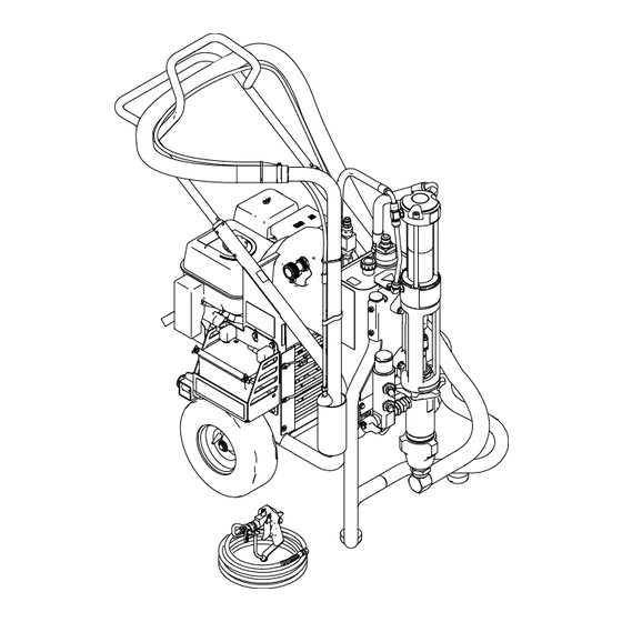
Page 4: Component Identification
Component Identification Component Identification Ref. Description Engine Controls Ignition Engine ON/OFF Switch Lift Location Suction Holder Trigger Lock Drain Valve Lock Ring Hydraulic Pump Valve Serial Number ID Label Pressure Control Hydraulic Oil Fill 311283J... -
Page 5: Operation
Operation Operation Pressure Relief Procedure General Repair Information Hydraulic system and engine may become very hot System pressure must be manually relieved to prevent during operation and could burn skin if touched. Flam- it from starting or spraying accidentally. Fluid under mable materials spilled on hot, bare engine could high pressure can be injected into the skin and cause cause fire or explosion. -
Page 6: Maintenance
Owner’s Manual for correct oil viscosity. Semi-annually Check belt wear; replace if necessary. Yearly or 2000 Replace hydraulic oil and filter element with Graco ISO 46 Hydraulic Oil hours 169236; 5 gallon/20 liter or 207428; 1 gallon/3.8 liter) and filter element 287871. -
Page 7: Troubleshooting
Clean filter used) is dirty or clogged Intake line to pump inlet is not tight Tighten Hydraulic motor is worn or damaged Bring sprayer to Graco distributor for repair Large pressure drop in fluid hose Use larger diameter or shorter hose... - Page 8 Fluid supply is low or empty Refill supply container. Excessive hydraulic pump noise Low hydraulic fluid level Turn sprayer OFF. Add fluid*. *Check hydraulic fluid level often. Do not allow it to become too low. Use only Graco approved hydraulic fluid, page 311283J...
-
Page 9: Compensator Seal Replacement
Compensator Seal Replacement Compensator Seal Replacement Removal 4. Install new gaskets and torque screws. Torque 50 in-lbs 4 plcs Compensator O-Ring Assembly Lubricate before installation 1. Relieve pressure, page 5. Allow hydraulic system to Gasket Adapter Note Gasket Orientation Block cool before beginning the service procedure. -
Page 10: Displacement Pump Replacement
Displacement Pump Replacement Displacement Pump Replacement See manual 311485 for pump repair instructions. 5. Remove clip (121). Removal 1. Flush pump (36). Stop pump on down stroke if possible. 2. Relieve pressure, page 5. 3. Remove suction set (147) from pump (36). ti7789 6. -
Page 11: Installation
Displacement Pump Replacement 8. Loosen jam nut (122) with a hammer. Unscrew 3. Hand tighten jam nut (122). Then tighten securely pump (36) from power head. 1/8 to 1/4 turn with hammer or torque to 330 ft-lb (447.4 N•m). ti7782 9. - Page 12 Displacement Pump Replacement 7. Install clip pin (121) to secure. 8. Install filter housing (110), page 15. ti7809 ti7772 9. Connect suction hose (147) to pump outlet (36). 311283J...
-
Page 13: Pump Power Head Replacement
Pump Power Head Replacement Pump Power Head Replacement Removal Installation 1. Install power head on unit. 1. Relieve pressure, page 5. 2. Remove hydraulic lines (100, 101) from head (75). ti7851 2. Tighten power head bolts (7). Torque bolts to 400 + 10 in-lb (45 + 1 N•m). -
Page 14: Hydraulic Motor
Hydraulic Motor Hydraulic Motor 450 in-lb (51 N•m) 600 in-lb (68 N•m) 60 in-lb (7 N•m) 930 in-lb (105 N•m) Torqued in 3 steps ti7868 311283J... -
Page 15: Filter Housing Replacement
Filter Housing Replacement Filter Housing Replacement Installation 1. Install filter housing (110) in pump opening. Removal 1. Relieve pressure, page 5. 2. Remove paint and drain lines from filter housing. ti7772 2. Tighten fitting. 3. Attach paint and drain lines. ti7845 3. -
Page 16: Hydraulic Pump Replacement
Place a container under hoses to catch any dripping oil. ti7784 Refilling Oil a. Replace drain plug. b. Fill tank with Graco Hydraulic Oil, ISO 46. Tank holds approximately 4 gallons. Removal ti7790 1. Relieve pressure, page 5. Allow hydraulic system to cool before beginning the service procedure. - Page 17 Hydraulic Pump Replacement 5. Remove four belt cover screws (79), washers (78) 7. Remove belt (19), page 20. and grommets (80) (2 each side). 8. Loosen set-screws (87) on front of large pulley (4). ti7796 6. Remove belt cover (67). ti7783 9.
- Page 18 Hydraulic Pump Replacement 11. Remove hydraulic pump (3). 2. Install new pump (3) in frame. 3. Install screws (9) and nuts (10). Torque to 225 + 10 in-lb (25.42 N•m). ti7800 12. Remove fittings (30, 34, 35) from pump (3) and set aside to use on the new pump.
- Page 19 Hydraulic Pump Replacement 6. Replace set-screws (87). Tighten and torque to 60 9. Install suction lines. Tighten fittings. Torque fitting A + 2 in-lb (6.8 + 0.2 N•m). to 225 + 10 in-lb (25.4 + 1.1 N•m). Fitting B to 450 +10 in-lb (50.1 + 1.1.
-
Page 20: Belt Removal And Replacement (Recommended Method)
Hydraulic Pump Replacement Belt Removal and Replacement Installing Belt (recommended method) a. Put belt over lower pulley (6) and align correctly. Removing Belt a. Place a ziptie around belt (19). b. Line up belt over top left side of large pulley (4). ziptie ti7843 ti7869... -
Page 21: Alternate Belt Removal And Installation
Hydraulic Pump Replacement Alternate Belt Removal and Installation b. Tighten engine bolts (21). Torque to 225 + 10 in-lb (25.4 + 1.1 N•m). Removing Belt c. Check belt (19) alignment on both large (4) and a. Loosen engine bolts (21) to relieve tension on small pulley (6). -
Page 22: Replacing Oil Reservoir
Hydraulic Pump Replacement Replacing Oil Reservoir Removal 4. Loosen and remove suction hose (153). 1. Relieve pressure, page 5. 2. Drain oil from reservoir (64) following Draining Oil procedure, page 16. Keep plug for use on new res- ervoir. ti7785 5. - Page 23 Hydraulic Pump Replacement Installation 8. Remove two top bolts (86) and two bottom nuts (84) securing reservoir (64) to frame. 1. Install plug (102), return elbow (31), suction fitting (32), inlet screen (89) and filter assembly (111) in new reservoir (64). ti7846 ti7893 ti7786...
- Page 24 Hydraulic Pump Replacement 3. Replace bolts (86) and nuts (84). Tighten bolts. 6. Reattach suction hose (153). Toque to 600 + 10 Torque to 125 + 10 in-lb 14 + 1.1 N•m). in-lb (68 + 1.1 N•m). 4. Connect coolant line to reservoir (64). Torque to 225 in-lb (14.1 N•m).
-
Page 25: Changing Hydraulic Fluid Filter
Changing Hydraulic Fluid Filter Changing Hydraulic Fluid Filter Removal Installation 1. Install new o-ring (113) from kit. 2. Install new filter (108) over cap (155). 3. Install cap (155) and filter (108) in filter housing 1. Relieve pressure, page 5. (111). -
Page 26: Cooler Replacement
Cooler Replacement Cooler Replacement 4. Remove screws (79), washers (78) and support bar (77) from cooling coil (72). Removal 1. Relieve pressure, page 5. 2. Loosen ground screw and remove ground clamp (95) from sprayer. ti7794 5. Remove coil (72) from sprayer frame. ti7799 3. - Page 27 Cooler Replacement Installation 3. Replace ground wire (95) and tighten screw. Torque to 25-30 in-lbs (2.8 - 3.4 N•m). 1. Install new coil (72). Replace support bar (77), washers (78) and screws (79). Tighten screws. ti7774 ti7768 2. Reconnect return line to oil tank and hydraulic line 4.
-
Page 28: Engine Replacement
Engine Replacement Engine Replacement Removing Pulley (6) NOTE: This procedure is only necessary if you are replacing the engine. When you install a new engine you reuse the existing pulley. Removal Removal 1. Relieve pressure, page 5. a. Loosen set screw (87) located on the side of 2. - Page 29 Engine Replacement ti20932a 311283J...
-
Page 30: Removing Handle
3. Remove frame tube plugs (120) located behind the wheels. Fixed Mounting (optional) To prevent damaging the unit when transporting it in a truck or on a trailer, Graco recommends fixed mounting to the vehicle. Repositioning Handle 4. Insert plugs (120) in upper frame handle tubes (a). -
Page 31: Securing Unit To Vehicle Bed
Removing Handle Securing Unit to Vehicle Bed For fixed mounting, fasten U-bolts over sprayer frame 2. Place U-bolts over sprayer frame and through holes as indicated in the following illustration. in vehicle bed. Place a washer and nut over bolt end. -
Page 32: Technical Data
Width inch (cm) 28 (71) Length inch (cm) 47 (119.3) Sound Levels* Sound Pressure 91 dB(A) Sound Power 106 dB(A) *measured at maximum normal load conditions Graco-Approved Hydraulic Oil 169236 - 5 gallons (19 liters) 207428 - 1 gallon (3.8 liters) 311283J... -
Page 33: Graco Standard Warranty
With the exception of any special, extended, or limited warranty published by Graco, Graco will, for a period of twelve months from the date of sale, repair or replace any part of the equipment determined by Graco to be defective. - Page 34 Original instructions. This manual contains English. MM 311283 Graco Headquarters: Minneapolis International Offices: Belgium, China, Japan, Korea GRACO INC. AND SUBSIDIARIES • P.O. BOX 1441 • MINNEAPOLIS MN 55440-1441 • USA Copyright 2006, Graco Inc. All Graco manufacturing locations are registered to ISO 9001. www.graco.com...
Need help?
Do you have a question about the 16U287 and is the answer not in the manual?
Questions and answers