
Related Manuals for Raritan TMCAT17 series


Summary of Contents for Raritan TMCAT17 series
- Page 1 TMCAT17 Series User Guide Release 1.0 Copyright © 2013 Raritan, Inc. TMCAT-0D-v1.0-E March 2013 255-37-0121-00...
- Page 2 Raritan, Inc. © Copyright 2013 Raritan, Inc. All third-party software and hardware mentioned in this document are registered trademarks or trademarks of and are the property of their respective holders.
- Page 3 In Raritan products which require Rack Mounting, please follow these precautions: Operation temperature in a closed rack environment may be greater than room temperature. Do not exceed the rated maximum ambient temperature of the appliances. See Specifications. Ensure sufficient airflow through the rack environment.
-
Page 4: Table Of Contents
Contents Chapter 1 Introduction Product Overview........................... 1 TMCAT17 Switch.........................1 MCCAT User Station ......................2 MCCAT Computer Interface Module (MCIM) ..............2 MCUTP Cable........................2 Product Photos ..........................3 Product Features ........................... 5 TMCAT17 Switch.........................5 MCCAT User Station ......................6 Package Contents.......................... 6 TMCAT17 Switch.........................6 MCCAT User Station (Optional) .................. - Page 5 Contents Activating the OSD........................29 Deactivating the OSD ........................29 Variations of Highlight Colors ...................... 29 Channel Colors ..........................30 What are Active and Inactive Channels ................30 Channel Colors and Statuses....................31 OSD Operation Keys ........................32 Chapter 4 Advanced Operation Switching the Channel Sorting.....................
- Page 6 Maximum Distance between Users and TMCAT17 Switches .............76 Maximum Distance between Users and Computers ..............76 Maximum Distance for User Station Direct Mode................77 Appendix C Compatibility with Other Raritan Products Analog KVM Switches ......................... 78 Digital KVM Switches........................78 Compatible CIMs ......................... 80 Connecting a Serial Device via the Serial CIM..............81...
- Page 7 Contents Appendix D Two-Tier System Overview ............................86 Limitations of the Two-Tier System .....................87 Establishing a Two-Tier System ....................87 STEP (A): Programme an MCCAT Switch as a Second-Tier Device ....... 87 STEP (B): Connect the Second-Tier MCCAT Switch to the Base Switch......88 STEP (C): Specify the Type of the Second-Tier Device on the OSD........89 STEP (D): Connect Computers to the TMCAT17 System ..........90 One-User MCCAT Switches ......................90...
-
Page 8: Chapter 1 Introduction
Category 5 (Cat5) unshielded twisted-pair (UTP) cables. If you connect Raritan's MasterConsole CAT (MCCAT) KVM switches to the TMCAT17 switch to form a "two-tier" system, the number of computers can be expanded up to 256 computers. -
Page 9: Mccat User Station
Chapter 1: Introduction MCCAT User Station An MCCAT user station connects a set of keyboard, mouse and monitor to a compatible KVM switch. After connecting the user station to the TMCAT17 switch, two users can access the system at a time. There is only one MCCAT user station model: MCCAT-UST. -
Page 10: Product Photos
Chapter 1: Introduction Model Cable length MCUTP06-PS2 0.6 meter (2 feet) MCUTP20-PS2 2 meters (6.5 feet) MCUTP40-PS2 4 meters (13 feet) MCUTP60-PS2 6 meters (20 feet) Sun USB type This type comes with an HD15 VGA connector, a Sun USB connector and an RJ-45 connector. - Page 11 Chapter 1: Introduction MCCAT-UST (Front and Rear View) MCUTP20-PS2 Cable MCUTP20-USB or MCUTP20-SUSB Cable...
-
Page 12: Product Features
Chapter 1: Introduction Product Features TMCAT17 Switch A user can control multiple computers per unit. The number of computers that can be controlled varies depending on the model you purchased: TMCAT1728 can control a maximum of 8 computers ... -
Page 13: Mccat User Station
Chapter 1: Introduction MCCAT User Station Interconnect with a compatible KVM switch via a standard Cat5 UTP cable Support a standard USB or PS/2 keyboard and mouse Easy firmware upgrade via a standard RS-232 serial cable Package Contents You may purchase the TMCAT17 switch alone or both of the TMCAT17 switch and MCCAT user station. -
Page 14: Tmcat17 Switch
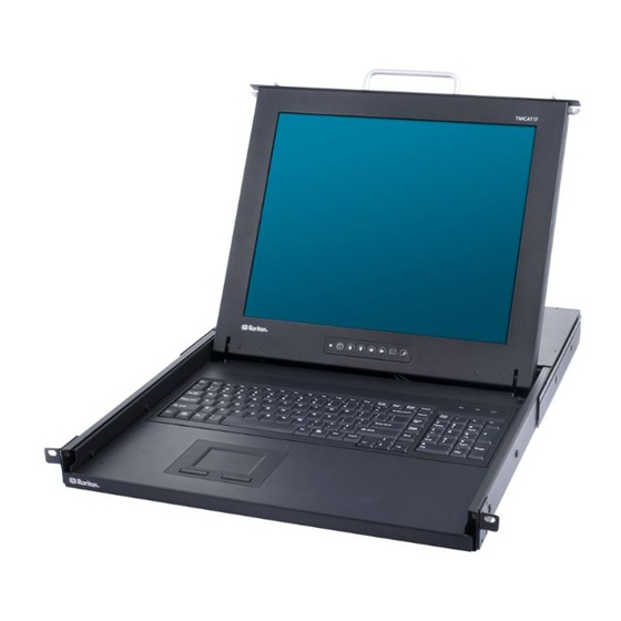
Chapter 1: Introduction TMCAT17 Switch Front View Handle Allows you to carry the TMCAT17 device or pull it out of the rack. Latches Lock or unlock the LCD panel and keyboard assembly. LCD display Displays the video. LCD controls Activate and navigate through the LCD OSD interface. Support brackets Support the TMCAT17 device when the brackets are inserted into the mounting brackets installed in the rack. -
Page 15: Mccat User Station
Chapter 1: Introduction Power switch Toggles the power on or off. Ground screw Connects a grounding wire. User 2 port Connects an optional MCCAT user station. Admin port Connects a computer for upgrading the firmware. Channel ports Connect computers. Depending on the model you purchased, the device may have 8 or 16 channel ports. - Page 16 Chapter 1: Introduction USB K/M ports Connect a USB keyboard and mouse. PS/2 keyboard port Connects a PS/2 keyboard. PS/2 mouse port Connects a PS/2 mouse. Power jack Connects a power adapter. Warning: Do NOT connect both PS/2 and USB keyboards or both PS/2 and USB mice simultaneously.
-
Page 17: Chapter 2 Quick Start
Quick Start Chapter 2 In This Chapter Before Installation..................10 Rackmount Installation ................11 Installing a Basic System.................14 Using the TMCAT17 Switch ..............20 Before Installation It is very important to locate the TMCAT17 in a suitable environment. The surface for placing and fixing the TMCAT17 should be stable and level or mounted into a suitable cabinet. -
Page 18: Rackmount Installation
Chapter 2: Quick Start Rackmount Installation Rackmount Kit Component list Mounting brackets M6 cage nuts M6 washers M6 screws... -
Page 19: Rack-Mounting The Tmcat17 Device
Chapter 2: Quick Start Rack-Mounting the TMCAT17 Device Before rack-mounting the device, make sure M6 cage nuts have been inserted into the holes of vertical rails where you intend to mount TMCAT17. To rack-mount the device: Adjust the mounting brackets to fit the depth of your rack. - Page 20 Chapter 2: Quick Start Pick up TMCAT17. Line up the rear of support brackets on the TMCAT17 with the front of mounting brackets installed in the rack. Push TMCAT17 to make the support brackets slide into the slots of mounting brackets.
-
Page 21: Installing A Basic System
Chapter 2: Quick Start Installing a Basic System Preparing Requisite Items Collect these components or devices before connecting computers. MCIMs or MCUTP cables (one per computer) If using MCIMs, Cat5 UTP cables are required The MCUTP cable is not compatible with Windows 98 operating system. - Page 22 Chapter 2: Quick Start - OR - If using MCIM-PS2 or PS/2 MCUTP cable: a. Plug the MCIM or MCUTP's PS/2 mouse connector into the computer's PS/2 mouse port. b. Plug the MCIM or MCUTP's PS/2 keyboard connector into the computer's PS/2 keyboard port.
- Page 23 Chapter 2: Quick Start - OR - If using the Sun USB MCUTP cable: a. Plug the MCUTP's Sun USB connector into one of the available USB ports on the Sun server. b. Plug the MCUTP's video connector into the VGA port on the Sun server.
-
Page 24: Connecting A User Station (Optional)
Connecting a User Station (Optional) You can connect the MCCAT user station to any compatible KVM switch, such as the "two-user" MCCAT switch or TMCAT17 series, to increase the number of users who can access the KVM switch and computers. - Page 25 Chapter 2: Quick Start b. Plug the keyboard's connector into the PS/2 or USB port on the user station. Warning: Do NOT connect both PS/2 and USB keyboards or both PS/2 and USB mice simultaneously. If you do so, only the USB keyboard and/or mouse work properly.
- Page 26 Chapter 2: Quick Start b. Plug the other end of the cable into the User 2 port of the KVM switch. 4. Connect the power adapter to the user station. a. Plug one end of the power adapter into the power jack of the user station.
-
Page 27: Using The Tmcat17 Switch
Chapter 2: Quick Start Using the TMCAT17 Switch Opening TMCAT17 This section describes how to physically open the LCD KVM switch when it is installed in a rack. Note: The diagrams are for illustration, and may not look exactly the same as the LCD KVM switch you purchased or the rack in your workplace. -
Page 28: Login
1. The Login box appears on the screen after turning ON the TMCAT17 system. 2. Type your user name and password. For example, if you are the administrator, the user name is "admin," and the default password is "raritan." a. Type admin in the User Name field, and press Enter. - Page 29 Chapter 2: Quick Start b. Type raritan in the Password field, and press Enter. The password is case sensitive. 3. The Selection Menu appears, indicating your login is successful. Important: It is strongly recommended to change the default password for the security of your TMCAT17 system.
-
Page 30: Accessing A Computer Or Channel
Chapter 2: Quick Start Accessing a Computer or Channel Use the Selection Menu to access any computer connected to the TMCAT17 switch. The first OSD menu that appears after login is the Selection Menu, which does not show any channel name by default until you assign them. To select a channel on the Selection Menu: 1. -
Page 31: Logout
Chapter 2: Quick Start For more information on the Selection Menu, see Selection Menu page 28) in the User Guide. Logout After completing your tasks in the TMCAT17 system, you should log out to prevent unauthorized people from accessing the system. To log out of the TMCAT17 system: 1. - Page 32 Chapter 2: Quick Start 2. Push the assembly of the LCD panel and keyboard tray back into the rack until you hear the click sound of latches. Note: If the assembly is stuck and cannot be pushed back, then push the black arrows on both sides while pushing back the assembly.
-
Page 33: Chapter 3 Introduction To The Osd Interface
Introduction to the OSD Interface Chapter 3 The OSD interface offers these functions: Channel selection System configuration Displaying product information In This Chapter OSD Layout..................... 26 Activating the OSD.................. 29 Deactivating the OSD ................29 Variations of Highlight Colors..............29 Channel Colors .................. -
Page 34: Osd Menu
Chapter 3: Introduction to the OSD Interface Message bar The location that displays messages or prompts relevant with current OSD screen. * Input/output devices refer to the keyboard, mouse, and monitor. OSD Menu Menu title The title of the current menu or submenu. Data display area The area that displays information or settings of the current menu or submenu. - Page 35 Chapter 3: Introduction to the OSD Interface Selection Menu In addition to the OSD menu's main layout, the Selection Menu provides additional elements, which are helpful for locating and selecting channels. Current page The number of current page. number Total of pages The total number of pages.
-
Page 36: Activating The Osd
Chapter 3: Introduction to the OSD Interface Activating the OSD The OSD disappears after you access any channel. To access a different channel or change the system settings, you must activate the OSD. To activate the OSD: Press the hot key (default: Scroll Lock) twice QUICKLY. You can assign a hot key other than Scroll Lock. -
Page 37: Channel Colors
Chapter 3: Introduction to the OSD Interface Channel Colors Different channel colors on the Selection Menu represent different channel statuses. Channel colors vary according to these criteria: The channels are active or inactive. See What are Active and Inactive Channels (on page 30). -
Page 38: Channel Colors And Statuses
Chapter 3: Introduction to the OSD Interface Inactive Channels The TMCAT17 switch recognizes a channel as being inactive when it does not detect that the channel port is connected to a powered CIM or MCUTP cable, which involves these scenarios: ... -
Page 39: Osd Operation Keys
Chapter 3: Introduction to the OSD Interface OSD Operation Keys When you have logged in to the system, and the OSD is displayed on the screen, you can use these keys to navigate through the OSD menus, change settings, and so on. To switch between menus: Function Switches to the Help menu... - Page 40 Chapter 3: Introduction to the OSD Interface Function make Cancels the current selection or the changes you make To exit from the menu or system: Function Exits from the current menu or submenu Logs you out of the TMCAT17 system Others: Function Toggles the Scan function on or off...
-
Page 41: Chapter 4 Advanced Operation
Advanced Operation Chapter 4 This chapter introduces more features about the operation of the product. If your TMCAT17 system is a two-tier system, make sure you follow these guidelines: All of the second-tier MCCAT switches have been programmed as the second-tier devices. -
Page 42: Switching The Channel Sorting
Chapter 4: Advanced Operation Switching the Channel Sorting The Selection Menu is sorted by channel number by default, but you can sort it based on channel names. To switch the channel sorting: Press F12 when the Selection Menu is displayed. The Selection Menu switches from the current sorting to the other sorting. -
Page 43: Cycling Through Channels
Chapter 4: Advanced Operation Cycling Through Channels You can turn on the Scan function to have the TMCAT17 system automatically display the video of every computer one by one on the screen. If the system scans a channel port where a second-tier device is connected, it will scan all channels of the second-tier device first before proceeding with the next channels on the base switch. -
Page 44: Sharing The Computer
Chapter 4: Advanced Operation When the Scan function is OFF The system allows you to select active channels only, which are displayed in green on the Selection Menu. To turn on the Skip function: 1. If you do not see the OSD on the screen, press the hot key twice QUICKLY to activate it. -
Page 45: Activating The Help Menu
Chapter 4: Advanced Operation To release the computer control: If you are the controlling user, you can release the computer control by doing one of these: Exit from the channel by selecting another channel or logging out Both of you and the other user who accesses the same channel stop using the keyboard and mouse for 5 seconds After the computer control is released, any user who first generates the keystroke or moves the mouse gains the control of the computer. -
Page 46: Supporting Sun Servers
Chapter 4: Advanced Operation Supporting Sun Servers The product supports Sun servers. To connect Sun servers, you must use the CIM or MCUTP cable designed for Sun servers, that is, DCIM-USB G2 or MCUTPxx-SUSB, where xx represents the cable length. To connect Sun servers via the MCUTPxx-SUSB cables: ... -
Page 47: Refreshing Channel Statuses
Chapter 4: Advanced Operation Combination Keys Table This table lists special Sun keys and corresponding combination keys. Sun key Combination keys Again Ctrl + Alt + F2 Props Ctrl + Alt + F3 Undo Ctrl + Alt + F4 Front Ctrl + Alt + F5 Copy Ctrl + Alt + F6... - Page 48 Chapter 4: Advanced Operation If few channels are impacted, you can access impacted channels one by one to update their channel statuses. See Accessing a Computer or Channel (on page 23).
-
Page 49: Chapter 5 System Settings
User name: admin Password: raritan If your TMCAT17 system is a two-tier system, make sure you follow these guidelines: All of the second-tier MCCAT switches have been programmed as the second-tier devices. -
Page 50: Assigning Or Modifying Channel Names
Chapter 5: System Settings Assigning or Modifying Channel Names By default there are no channel names assigned to any connected devices on the Selection Menu. Only channel port numbers are available. It is not easy to identify the computers or devices without appropriate channel names, so you should specify a channel name for each connected computer or device. -
Page 51: Changing The Scan Rate
Chapter 5: System Settings Changing the Scan Rate When the Scan function is ON, the system scans each channel for 5 seconds by default. You can change the scan rate of each channel. Valid range is 5 to 24 seconds. To change scan rates: 1. -
Page 52: Changing Passwords
It is strongly recommended to change the default password for the security of your TMCAT17 system. The default password for the administrator account (Admin) is "raritan" (all lower case), and there are no passwords for any user accounts by default. -
Page 53: Changing The Hot Key
Chapter 5: System Settings 8. The message "Confirm password" appears on the message bar. Re-type the new password, and press Enter. When the message "Password Changed" appears on the message bar, the password is changed successfully. 9. Repeat Steps 4 to 8 to change the passwords for other user accounts. Important: Write down your new passwords and keep them in a safe place. -
Page 54: Changing The Operation Mode
Chapter 5: System Settings Changing the Operation Mode There are two operation modes in the TMCAT17 system: Private and PC Share modes. Private mode: When a user is accessing any channel, the other user cannot access the same channel unless the first user exits from that channel. -
Page 55: Setting Up The Green Mode
Chapter 5: System Settings Setting Up the Green Mode Green Mode is the power-saving mode for the monitor. When the TMCAT17 system does NOT detect any keystrokes or mouse activities for a preset period of time after you access a channel, the system enters the Green Mode, and the screen becomes blank. -
Page 56: Setting Up The Logoff Timeout Function
Chapter 5: System Settings If pressing Esc, the message “Save the changes [Y/N/ESC]” appears on the message bar. Press Y to save the changes, N to abort the changes, or Esc to return to the current menu or submenu. Setting Up the Logoff Timeout Function You can turn on the Logoff Timeout feature so when a logged-in user stops using the keyboard and mouse for a preset period of time, the... -
Page 57: Hiding The Login Box
Chapter 5: System Settings If pressing Esc, the message “Save the changes [Y/N/ESC]” appears on the message bar. Press Y to save the changes, N to abort the changes, or Esc to return to the current menu or submenu. Hiding the Login Box The Login box is continuously displayed on the screen by default. -
Page 58: Managing User Accounts
Chapter 5: System Settings 3. Press S to save the changes or Esc to quit the current menu or submenu. If pressing Esc, the message “Save the changes [Y/N/ESC]” appears on the message bar. Press Y to save the changes, N to abort the changes, or Esc to return to the current menu or submenu. -
Page 59: Deleting User Accounts
Chapter 5: System Settings 3. Select the second submenu, User Configuration. To select the submenu, either press 2, or press to highlight it and then press Enter. The User Configuration submenu appears. 4. Press Insert. The system creates a new user account with the name syntax—User<xx>, where <xx>... -
Page 60: Setting Up The Channel Id Display Function
Chapter 5: System Settings Setting Up the Channel ID Display Function Whenever you access any channel to which a computer or any non-KVM-switch device is connected, a line of text comprising the device name, channel number and name appears on the screen for seconds. The line is the "ID"... -
Page 61: Adjusting The Id Display Position
Chapter 5: System Settings To display the ID continuously on the screen, select "- -" (dashes). 7. Press S to save the changes or Esc to quit the current menu or submenu. If pressing Esc, the message “Save the changes [Y/N/ESC]” appears on the message bar. -
Page 62: Adjusting The Osd Menu Position
Chapter 5: System Settings Adjusting the OSD Menu Position You may move the OSD menu to the position you prefer on the screen. To adjust the OSD menu position: 1. If you do not see the OSD on the screen, press the hot key twice QUICKLY to activate it. - Page 63 Chapter 5: System Settings 4. The message "Reset To Default [Y/N/ESC]" appears on the message bar. Press Y to reset the system, or N or Esc to cancel the reset. 5. When you hear the beep sound and see the login box displayed on the screen, the system reset is complete.
-
Page 64: Chapter 6 Lcd Panel Operation
LCD Panel Operation Chapter 6 You can customize visual display properties of the built-in LCD display, such as colors and image position, by changing the settings on the LCD OSD menu. In This Chapter LCD Controls ...................57 LCD OSD Layout..................58 OSD Submenus..................58 Changing LCD OSD Settings ..............60 Auto-Adjusting Display Settings ..............61... -
Page 65: Lcd Osd Layout
Chapter 6: LCD Panel Operation LCD OSD Layout You can view the LCD information, and adjust the visual images displayed and the LCD OSD properties through LCD OSD menus. Number Information Description OSD title The bar shows the LCD version, and the resolution and refresh rate applied to current video image. -
Page 66: Image
Chapter 6: LCD Panel Operation Image This submenu determines how the screen image is displayed. Brightness: Adjust background black level of the screen image. Contrast: Adjust the difference between the image background (black level) and the foreground (white level). ... -
Page 67: Misc
Chapter 6: LCD Panel Operation Auto Adjust: Fine tune the video signal to eliminate waviness and distortion. The "Auto Adjusting" message is displayed during the process. H Position: Align the screen image left or right. V Position: Align the screen image up or down. ... -
Page 68: Auto-Adjusting Display Settings
Chapter 6: LCD Panel Operation 2. Press to select the submenu (icon) you want, and press to confirm. When a submenu is selected, it is highlighted in orange. 3. Press to select the field whose value or option you want to change. -
Page 69: Resetting Lcd Osd Settings
Chapter 6: LCD Panel Operation 4. Press to select the option, Yes, and then press confirm. A message "Auto Adjusting" is displayed on the screen, and the screen flickers momentarily until it finds the ideal profile. Resetting LCD OSD Settings You can restore all of LCD OSD settings to factory defaults at any time. -
Page 70: Chapter 7 Keyboard Layout Settings (For Sun Usb Mcutp Cable)
Keyboard Layout Settings (for Sun Chapter 7 USB MCUTP Cable) Different language versions of keyboards are provided for use in different countries. For example, the layout of a French keyboard is different from that of a US English keyboard. With the Sun USB MCUTP cable, you can change the keyboard's layout setting to match your keyboard type if you are not using a US English keyboard (the factory default). - Page 71 Chapter 7: Keyboard Layout Settings (for Sun USB MCUTP Cable) 3. Press Left Ctrl + NumLock to enter the setting mode. A message similar to the following appears in the text editor. Frequently-used keyboard layout codes Current keyboard layout is US English (code 33) 4.
-
Page 72: Keyboard Layout Codes
Chapter 7: Keyboard Layout Settings (for Sun USB MCUTP Cable) Newly-changed keyboard code 5. Press Esc to exit the setting mode. 6. Log out of the server. If a message appears, asking whether you want to save the text file, you can ignore it. -
Page 73: Chapter 8 User Station Direct Mode
User Station Direct Mode Chapter 8 Sometimes when you have to cope with an emergency, such as the crash cart operation, you may need to connect the MCCAT user station to the computer directly. This is called Direct Mode. To connect the MCCAT user station to the computer: 1. - Page 74 Chapter 8: User Station Direct Mode If using the MCUTP cable: Plug the RJ-45 connector of the cable into the Cat5 Port of the user station. Note: If any abnormal video issues occur, power cycle the MCCAT user station by unplugging and re-plugging its power adapter to resolve the problem.
-
Page 75: Chapter 9 Firmware Upgrade
5. Click Firmware Upgrade. The webpage showing a list of firmware files opens. If this is your first time to download the firmware from the Raritan website, the Firmware Request form opens. Fill in the form, and click Submit. -
Page 76: Step (B): Connect The Desired Device To The Computer Running The Upgrade Utility
TMCAT17 switch or MCCAT user station to the computer where the upgrade utility is installed. Note: If you don't have the cable, contact Raritan Technical Support for assistance. 1. Plug one end of the serial cable into one of the computer's serial ports. -
Page 77: Step (C): Launch The Upgrade Utility
STEP (C): Launch the Upgrade Utility The upgrade utility for TMCAT17 switch and MCCAT user station is the same one for Raritan Paragon devices, that is, the Paragon Update utility. Paragon Update utility older than 2.4.3 does not support upgrading the TMCAT17 switch and MCCAT user station. - Page 78 Chapter 9: Firmware Upgrade e. Ensure <Default No Encryption> is selected in the Encryption Key field. (Optional) Click Save to save the device information so that next time you don't have to specify the same information again. 3. Select the checkbox next to the device that you want to upgrade. 4.
- Page 79 Click Yes. The Check Device Information window opens. b. To quit the window, click OK. Note: MCCAT and TMCAT17 series belong to the same hardware type. The Check Device Information window always shows the hardware is MCCAT no matter the connected KVM switch is MCCAT or TMCAT17 series.
-
Page 80: Appendix A Specifications
Appendix A Specifications In This Chapter TMCAT17 Specifications .................73 Supported Video Resolutions ..............74 TMCAT17 Specifications Generic TMCAT1728 TMCAT17216 Form factor 1U 19" rackmountable (482.6mm), can be mounted in 750mm and 900mm cabinets Display type Grade A+ LCD, TFT panel display Display size 17"... -
Page 81: Supported Video Resolutions
Appendix A: Specifications Storage temperature -5° to 60° C Humidity 5~90% RH, non-condensing Power AC, 110-240V, 50~60Hz, auto-switching Certification FCC, CE, UL, RoHS Supported Video Resolutions Note: The integrated LCD display supports the video resolution up to 1280x1024 only, but the external monitor, which is connected to the TMCAT17 switch via the MCCAT user station, can support the resolution up to 1600x1200. - Page 82 Appendix A: Specifications Screen resolution Refresh rate (HZ) 1280x1024 60, 75, 85 1600x1200...
-
Page 83: Appendix B Cable Length Limitations
Appendix B Cable Length Limitations You should limit the Cat5 cable length between TMCAT17 system components and connected computers for keeping optimal video quality. This section lists the maximum cable length or distance supported in different scenarios. In This Chapter Maximum Distance between Users and TMCAT17 Switches....76 Maximum Distance between Users and Computers .......76 Maximum Distance for User Station Direct Mode ........77... -
Page 84: Maximum Distance For User Station Direct Mode
Appendix B: Cable Length Limitations Maximum Distance for User Station Direct Mode When you connect the MCCAT user station to a computer directly, that is, the Direct Mode, you should also limit the cable length for video quality. For information on the Direct Mode, see User Station Direct Mode page 66). -
Page 85: Appendix C Compatibility With Other Raritan Products
(http://www.raritan.com/support/firmware-and-documentation/). Digital KVM Switches The TMCAT17 switch is compatible with all of Raritan's Dominion KX II KVM switches except for Dominion KX II-101. Instead of connecting a VGA monitor, mouse and keyboard to the Dominion KX II device for local access and configuration, you can connect a TMCAT17 switch to it. - Page 86 Appendix C: Compatibility with Other Raritan Products Plug the MCIM or CIM's VGA and PS/2 or USB connectors into the appropriate ports labeled LOCAL USER on the Dominion KX II device. Note: For a list of CIMs compatible with TMCAT17, see...
-
Page 87: Compatible Cims
Compatible CIMs In addition to MCIM-PS2 and MCIM-USB, the TMCAT17 switch is also compatible with other Raritan Computer Interface Modules (CIMs). See the table in this section for information. The way to connect these CIMs is the same as the way to connect MCIMs. -
Page 88: Connecting A Serial Device Via The Serial Cim
To connect an ASCII serial device, LAN/WAN component or a computer through an RS-232 serial port to the TMCAT17 system, use one of Raritan's serial CIMs: P2CIM-SER or P2CIM-SER-EU. These CIMs can emulate an ASCII terminal and convert the serial data from the ASCII device to VGA video (800x600x60) and PS/2 keyboard signals. - Page 89 2. Connect the CIM to the KVM switch, using a standard Cat5 UTP cable. 3. Plug the CIM's USB connector into a powered USB port, or into a separately available Raritan PWR-SER-4 power adapter, to obtain power. For detailed information on the CIMs, see Paragon and Dominion KX...
-
Page 90: P2-Eust User Station
Note: If your P2-EUST's firmware is higher than 3F0, you must downgrade the device to 3F0 or earlier versions for compatibility with TMCAT1728/216 switches. For more information on P2-EUST, see the Paragon II User Guide, which can be downloaded from the Raritan website's Firmware and Documentation section (http://www.raritan.com/support/firmware-and-documentation/). -
Page 91: Supported Maximum Cable Length
Appendix C: Compatibility with Other Raritan Products 3. Connect the user station to the KVM switch via a standard Cat5 UTP cable. 4. Connect the power cord to the user station. 5. Turn on the user station and the monitor. -
Page 92: Appendix D Two-Tier System
If the system completely comprises the 16-channel-port models, the number of connected computers can be expanded up to 256 computers. Note: User documentation for MCCAT switches can be downloaded from Raritan website's Firmware and Documentation section (http://www.raritan.com/support/firmware-and-documentation/). In This Chapter Overview....................86... -
Page 93: Overview
Appendix D: Two-Tier System Overview When you connect one MCCAT switch or more to a TMCAT17 switch, you are organizing a "two-tier" system. All MCCAT switches connected to the same TMCAT17 switch are the SECOND-TIER devices, and the TMCAT17 switch that connects these second-tier devices is the "base switch,"... -
Page 94: Limitations Of The Two-Tier System
Appendix D: Two-Tier System Limitations of the Two-Tier System The two-tier system has several limitations. There is only one path (Cat5 UTP cable) between the base switch and each second-tier device. When a user from the base switch is accessing any channel of a second-tier device, there are no other paths left for the other user from the base switch to access the same second-tier device's channels. -
Page 95: Step (B): Connect The Second-Tier Mccat Switch To The Base Switch
Appendix D: Two-Tier System The TIER LED will be lit continuously, indicating that the MCCAT switch has been programmed as a second-tier device. 4. Repeat Steps 1 to 3 to change the programming of more MCCAT switches. Note: To programme a second-tier device back as the base switch, follow the same procedure in this section but press the channel number 1 button instead. -
Page 96: Step (C): Specify The Type Of The Second-Tier Device On The Osd
Appendix D: Two-Tier System 4. Turn ON all second-tier devices. 5. After hearing the beep sound from the second-tier devices, turn ON the base switch. Important: Make sure you turn on second-tier devices before turning on the base switch so that the base switch downloads up-to-date channel data from second-tier devices. -
Page 97: Step (D): Connect Computers To The Tmcat17 System
Appendix D: Two-Tier System If pressing Esc, the message “Save the changes [Y/N/ESC]” appears on the message bar. Press Y to save the changes, N to abort the changes, or Esc to return to the current menu or submenu. STEP (D): Connect Computers to the TMCAT17 System You can connect computers to available channel ports of any KVM switch in the system, including channel ports on the base switch and second-tier... -
Page 98: How To Connect Mccat18/116 Switches To The Base Switch
Appendix D: Two-Tier System How to Connect MCCAT18/116 Switches to the Base Switch A "one-user" MCCAT switch requires one MCIM-PS2 for connecting to the base switch. Do NOT use MCUTP cables or any CIM other than MCIM-PS2 to connect "one-user" MCCAT switches to the base switch. To connect "one-user"... -
Page 99: Setting Up The Second-Tier Channels
Appendix D: Two-Tier System b. Plug the other end of the Cat5 UTP cable into one of the channel ports on the base switch. 4. Repeat previous step(s) to connect other second-tier MCCAT switches to the base switch. 5. Turn ON all second-tier devices. 6. -
Page 100: Accessing The Second-Tier Channels
Appendix D: Two-Tier System 4. If you do not find the channel on the current page, press Page Down or Page Up to go to the next or previous page. 5. Press to highlight the channel where a second-tier MCCAT switch is connected, and press G. -
Page 101: Returning To The Base Switch's Osd
Appendix D: Two-Tier System 4. If you do not find the channel on the current page, press Page Down or Page Up to go to the next or previous page. 5. Press to highlight the channel you want. 6. Press Enter. The video of the accessed computer appears on the screen. -
Page 102: Appendix E Ground Screw
Appendix E Ground Screw If you want to prevent any electrical shock, you can use the ground screw on the rear panel to provide a safe electrical path to the ground. To prevent any potential shock hazard: Connect the ground screw to a wiring system or wiring device. -
Page 103: Appendix F Resetting To Factory Defaults
3. Release the reset button after the TMCAT17 device is powered ON and the Login box appears on the screen. Default Settings Field or function Factory default Administrator password raritan (all lower case) User passwords No passwords for any user account (User01~User07) Scan rate 5 seconds per channel Operation Mode... - Page 104 Appendix F: Resetting to Factory Defaults Field or function Factory default Login Blank Timing 5 minutes Logoff Timeout Timing 5 minutes...
-
Page 105: Appendix G Troubleshooting
TMCAT17 switch may have no display, become monochrome instead of color, or become unstable. If this is the case, you will need to provide a proper ID-pattern to the display card. Call Raritan Technical Support (see the last page) for help if necessary. ... - Page 106 If the problem persists, then the computer's mouse port is locks (unable to control mouse functions) when out of order. Otherwise, contact your dealer or Raritan for help. a particular computer is If the problem occurs after the TMCAT17 switch has been installed...
- Page 107 Keyboard Layout Settings (for Sun USB Closing TMCAT17 • 24 MCUTP Cable) • 63 Combination Keys Table • 40 Compatibility with Other Raritan Products • 78 Compatible CIMs • 79, 80 Connecting a Serial Device via the Serial CIM • LCD Controls • 57 LCD OSD Layout •...
-
Page 108: Index
Index Maximum Distance between Users and Computers • 76 Maximum Distance between Users and Selection Menu • 24, 28 TMCAT17 Switches • 76 Setting Up the Channel ID Display Function • Maximum Distance for User Station Direct Mode • 77 Setting Up the Green Mode •... - Page 109 Index What are Active and Inactive Channels • 5, 30,...
-
Page 110: United Kingdom
For CommandCenter Secure Gateway: Press 6, then Press 2 Phone: +31-10-2844040 Fax: 732-764-8887 Email: tech.europe@raritan.com Email for CommandCenter NOC: tech-ccnoc@raritan.com Email for all other products: tech@raritan.com United Kingdom Monday - Friday 8:30 a.m. to 5 p.m. GMT China Phone +44(0)20-7090-1390...
Need help?
Do you have a question about the TMCAT17 series and is the answer not in the manual?
Questions and answers