Table of Contents
Advertisement
Instructions
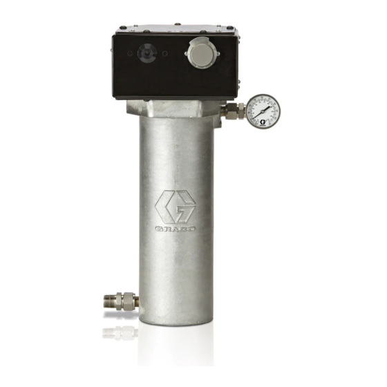
High Pressure Fluid Heater
VISCON HP
Used for variable heating of fluids.
7250 psi (50 MPa, 500 bar) Maximum Working Pressure
Important Safety Instructions
Read all warnings and instructions in this manual.
Save these instructions.
See page 2 for model numbers, descriptions, and
approvals information.
See page 3 for Table of Contents.
Hazardous Location Heater shown
309524L
TI12338A
Advertisement
Table of Contents

Related Manuals for Graco VISCON HP 309524L


Summary of Contents for Graco VISCON HP 309524L
- Page 1 Instructions High Pressure Fluid Heater VISCON HP Used for variable heating of fluids. 7250 psi (50 MPa, 500 bar) Maximum Working Pressure Important Safety Instructions Read all warnings and instructions in this manual. Save these instructions. See page 2 for model numbers, descriptions, and approvals information.
-
Page 2: Non-Hazardous Location Heaters
Models Models Hazardous Location Heaters Part No. VAC (50/60 Hz single phase) / Watts / Amps Series 245848 245863 245864 245862 246254 Non-hazardous Location Heaters Model No. VAC (50/60 Hz single phase) / Watts / Amps Series 245867 245868 245869 245870 246276 120 / 2300 / 19.2... -
Page 3: Table Of Contents
Graco Standard Warranty ....30 Graco Information ......30... -
Page 4: Warning
Warning SKIN INJECTION HAZARD High-pressure fluid from gun, hose leaks, or ruptured components will pierce skin. This may look like just a cut, but it is a serious injury that can result in amputation. Get immediate surgical treatment. • Do not point the gun at anyone or at any part of the body. •... - Page 5 Misuse can cause serious injury or death. • For professional use only. • Use equipment only for its intended purpose. Call your Graco distributor for information. • Read manuals, warnings, tags, and labels before operating equipment. Follow instructions. • Check equipment daily. Repair or replace worn or damaged parts immediately.
-
Page 6: Installation
Installation Installation Typical Installation Drawing The typical installation drawing is only a guide. Your Graco distributor can assist in designing your system. Key: Bleed-type Master Air Valve Air Filter Air Regulator and Gauge Air Line Lubricator Pump Runaway Valve Ground Wire... -
Page 7: Selecting Tubing
WARNING Read warnings, pages 4-5. • Select system components that meet temper- ature and pressure ratings listed in Technical Data, page 28. The heater’s normal output range is adjustable from 84-220°F (29-104°C). • Locate heater away from all flammable mate- rials and where operators will not come in contact with hot metal surfaces. -
Page 8: Mounting Heater
Installation Mounting Heater • The heater has a surface temperature of T2 (482°F, 250°C). Follow temperature code when locating heater. See Technical Data, page 28, for more temperature code informa- tion. • Heater controls must be easily accessible. • The mounting surface must be able to support the weight of the heater and fluid, and any stress caused during operation. -
Page 9: Fluid Connections & Accessories
Cart Mounting . 5) You need to have 2 each of cart mounting bar 183485 and clamp 183484. See Accessories, page 26, to order. 1. Place clamps (AA) around the cart vertical post (DD) and secure to the heater mounting bars (ZZ) with M8 x 1.25 x 30 mm bolts (6) and lockwasher (5). -
Page 10: Electrical Connections
5 full threads engaged and an 8 mm length of engaged threads. The above accessories are not provided by Graco. Make sure that accessories are appropri- ate for the conditions of use. 309524L... - Page 11 Wall Mounted Wiring Mount a 2-pole, explosion-proof electric switch (H) near the heater. See F . 7. The switch must meet the electri- cal codes for your location. Also use the correct cable and plug. Power terminal Ground terminal Neutral terminal or 2nd Tighten all terminal nuts to power terminal 30 in-lb (3.4 N•m)
-
Page 12: Determining Proper Fluid Temperature
Note that most of the viscosity reduction occurs by 130°F (55°C). Under-Boil is the Graco method of hot, airless spraying where the fluid is heated to a temperature just under the boiling point of its most volatile solvent. - Page 13 (60) . 10: Effect of Temperature on Viscosity The chart in F . 10 shows the effect of temperature in reducing two fluids to a sprayable viscosity, between 20 and 34 seconds using a No. 2 Zahn cup. Note that temperature has more of an effect on high solid fluids than on thin enamels.
-
Page 14: Operation
Operation Operation Pressure Relief Procedure WARNING Read warnings, page 4. Follow Pressure Relief Procedure when you stop spraying, and before cleaning, checking, or servicing equipment. 1. Engage the gun safety lock. 2. Shut off main power to the heater. 3. Circulate fluid for at least 10 minutes to cool the heated fluid and heater. -
Page 15: Setting Heater Control
Setting Heater Control (Refer to F . 11) 1. Set the heater control knob (33) to a trial setpoint of 4 or 5. 2. Start the pump and circulate fluid through the sys- tem at very low pressure, about 10-12 oz/min (0.30-0.35 liter/min). -
Page 16: Maintenance
Maintenance Maintenance WARNING Read warnings, pages 4 and 5. Make sure the main power is off and heater is cool before doing mainte- nance. Flushing Clogged fluid passages are difficult to clean and reduce heating efficiency, flow rate, and pressure. Flush fre- quently, including whenever system is not in use. -
Page 17: Troubleshooting
Troubleshooting Problem Heater will not heat. Temperature too low. Temperature too high. High fluctuating temperatures, about 220-250°F (104-120°C) at 0.1 GPM. Too much pressure drop or fluid will not flow. Heater fittings leak. 300°F (149°C) . 14: Electrical Schematic 309524L Cause No current. -
Page 18: Repair
Repair Repair WARNING Read warnings, pages 4-5. Make sure the main power is off and heater is cool before repairing. Hazardous Location Heaters: See F Non-hazardous Location Heaters: See F Primary Thermostat & Probe 1. Follow Pressure Relief Procedure, page 14. 2. - Page 19 REF. 10 Wiring Diagram Apply thermal lubricant Torque to 89 in-lb (10 N•m) Torque nuts (62) to 10-12 in-lb (1.1-1.3 N•m) . 15: Thermostat Repair – Hazardous Location Heaters REF. 10 Wiring Diagram Apply thermal lubricant Torque to 89 in-lb (10 N•m) Torque nuts (62) to 10-12 in-lb (1.1-1.3 N•m) .
-
Page 20: Thermal Limit Sensor
Repair Thermal Limit Sensor CAUTION To avoid damaging the capillary tube (GG), which can cause heater malfunction, do not kink or nick the tube. To avoid shorting out the heater, do not allow the cap- illary tube to contact the block terminal (3A). 1. - Page 21 Torque to 89 in-lb (10 N•m) Electrical Housing Junction Box Apply sealant Torque nuts (62) to 10-12 in-lb (1.1-1.3 N•m) . 17: Control Repair – Hazardous Location Heaters Torque to 89 in-lb (10 N•m) Electrical Housing Apply sealant Torque nuts (62) to 10-12 in-lb (1.1-1.3 N•m) .
-
Page 22: Parts
Parts Parts Hazardous Location Heaters 14, 43 14, 36 REF. 1 29 30 33 Torque to 89 in-lb (10 N•m) Apply sealant Apply thermal lubricant Torque nuts (62) to 10-12 in-lb (1.1-1.3 N•m) ti2334E 309524L... - Page 23 Hazardous Location Heaters Ref. No. 3 Heater Block Part No. Series Part No. 245848 246616 245862 246617 245863 246618 245864 246619 246254 246620 Ref. Part No. Description 183074 CONTROL HOUSING 102124 THERMOMETER DIAL HEATER BLOCK; see table; includes ref. no. 2, 31, 32, 56 183066 COVER 107542 LOCKWASHER 109114 SCREW;...
-
Page 24: Non-Hazardous Location Heaters
Parts Non-Hazardous Location Heaters 14, 43 14, 36 35 25 29 30 Torque to 89 in-lb (10 N•m) Apply sealant Apply thermal lubricant Torque nuts (62) to 10-12 in-lb (1.1-1.3 N•m) TI2336E 309524L... - Page 25 Non-Hazardous Location Heaters Ref. No. 3 Heater Block Part No. Series Part No. 245867 246616 245868 246617 245869 246618 245870 246619 246276 246620 Ref. Part No. Description 15A809 ENCLOSURE 102124 THERMOMETER DIAL HEATER BLOCK; see table; includes ref. no. 2, 31, 32, 56 15A811 BOTTOM COVER 107542 LOCKWASHER 109114 SCREW...
-
Page 26: Accessories
Accessories Accessories Heater Conversion Kit 246302: Includes two fittings to make VISCON HP ports match VISCON Mounting Bracket 192585: European version (see below) Measurements – inches (mm) 6.76 0.88 3.37 (127) (171.7) (22.4) (85.5) 183982: USA version (152) (127) Cart Bracket Order 2 each of the following: 183484: Clamp 183485: Mounting bar... - Page 27 Cable Clamp Kit 246303 Installation 1. Slide cable clamp (3) onto cable (2). 2. Place washer (F) on fitting (E). 3. Push conical-shaped packing (D) into fitting (E). 4. Place washer (C) on retaining nut (B). Ref. Part No. Description Cable, 16.4 ft.
-
Page 28: Technical Data
Technical Data Technical Data The heater can be used in the following environmental conditions: indoor use, 99% maximum relative humidity, pollu- tion degree 2, installation category II, maximum ambient temperature 135° F (57° C). Maximum Working Pressure ..... . 7250 psi (50 MPa, 500 bar) Voltage / Wattage / Current* . -
Page 29: Dimensions
Dimensions 3/4 npt(f) Electrical Conduit Port 1/2 npt(m) Fluid Inlet 309524L Measurements – inches (mm) 9.375 (238) 1/2 npt(f) Fluid Outlet Dimensions 8.46 6.375 (215) (165) (457) (162) -
Page 30: Graco Standard Warranty
With the exception of any special, extended, or limited warranty published by Graco, Graco will, for a period of twelve months from the date of sale, repair or replace any part of the equipment determined by Graco to be defective.
Need help?
Do you have a question about the VISCON HP 309524L and is the answer not in the manual?
Questions and answers
How do I separate the heater core from its housing?
To separate the heater core from the housing on a Graco VISCON HP 309524L:
1. Follow the Pressure Relief Procedure (page 14).
2. Turn the control knob (33) to setpoint 1.
3. Loosen the setscrew (30) in the control knob (33).
4. Remove the control knob (33).
5. Remove the adjusting knob (12) from the control knob (33).
6. Remove the 6 screws (6) and lockwashers (5) holding the housing to the heater block (3).
7. Lift the housing away from the heater block.
This separates the heater core from the housing.
This answer is automatically generated
how does the heater core get removed from its housing
To remove the heater core (heater block) from the housing in a Graco VISCON HP 309524L:
1. Follow the Pressure Relief Procedure (page 14).
2. Turn control knob (33) to setpoint 1.
3. Loosen setscrew (30) in control knob (33).
4. Remove control knob (33).
5. Remove adjusting knob (12) from control knob (33) and press-fit it onto the new knob if replacing.
6. Check bushing (29) and replace if worn.
7. Remove the six screws (6) and lockwashers (5) holding the housing to the heater block (3).
8. Remove the primary thermostat and probe (24), backup thermostat (10), thermal limit sensor (15), and control knob (33).
9. Unscrew the heater block from the housing.
Reassemble the unit in the reverse order of disassembly.
This answer is automatically generated