Table of Contents
Advertisement
Quick Links
Instructions
VISCON
High Flow, High Pressure Fluid Heater
For variable heating of viscous fluids. For professional use only.
7250 psi (50 MPa, 500 bar) Maximum Working Pressure
See page 3 for model information and approvals.
Important Safety Instructions
Read all warnings and instructions in this
manual before using the equipment. Save
these instructions.
Externally Controlled, RTD
Feedback Model
®
HF
Thermostat-
Controlled
ti20051a
Thermostat-
Controlled for XP-hf
3A2954T
EN
Advertisement
Table of Contents

Related Manuals for Graco VISCON HF


Summary of Contents for Graco VISCON HF
- Page 1 Instructions ® VISCON 3A2954T High Flow, High Pressure Fluid Heater For variable heating of viscous fluids. For professional use only. 7250 psi (50 MPa, 500 bar) Maximum Working Pressure See page 3 for model information and approvals. Important Safety Instructions Read all warnings and instructions in this manual before using the equipment.
-
Page 2: Table Of Contents
Graco Standard Warranty ....52 Graco Information ......52... -
Page 3: Models
Models Models Hazardous Location Heaters See SPECIAL CONDITIONS FOR SAFE USE, page 5. VAC (50/60 Hz single Approvals Model Series Description phase) / Watts / Amps 24W248 Thermostat Control 240 / 5400 / 22.5 2575 RTD, For Use With 24W612 External Digital 240 / 5400 / 22.5 0359... -
Page 4: Non-Hazardous Location Heaters
Models Non-Hazardous Location Heaters VAC (50/60 Hz single Approvals Model Series Description phase) / Watts / Amps 24P016 Thermostat Control 240 / 5400 / 22.5 Thermostat Control, 25C961 240 / 5400 / 22.5 For XP-hf 5024314 Certified to CAN/CSA STD C22.2 No. 88 RTD, For Use With Conforms to UL STD 499 262853... -
Page 5: Warnings
• For information on the required dimensions of the flameproof joints contact the holder of this certificate (Graco Inc); Flamepath joints are not intended to be repaired. • Special fasteners for securing equipment covers shall have a minimum yield strength of 1,100 MPa and be corrosion resistant and sized M8 x 1.25 x 30. - Page 6 Warnings WARNING FIRE AND EXPLOSION HAZARD Flammable fumes, such as solvent and paint fumes, in work area can ignite or explode. Paint or solvent flowing through the equipment can cause static sparking. To help prevent fire and explosion: • Use equipment only in well-ventilated area. •...
- Page 7 Warnings WARNING EQUIPMENT MISUSE HAZARD Misuse can cause death or serious injury. • Do not operate the unit when fatigued or under the influence of drugs or alcohol. • Do not exceed the maximum working pressure or temperature rating of the lowest rated system component.
-
Page 8: Typical Installation
Typical Installation Typical Installation The typical installation drawing is only a guide. Your Graco distributor can assist in designing your system. 05486-524 . 1: Typical Installation – Heated Circulating System Key: Bleed-type Master Air Valve Fluid Pressure Regulator Air Filter... -
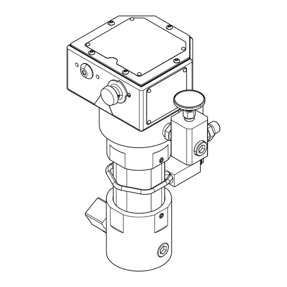
Page 9: Component Identification
Component Identification Component Identification Thermostat Controlled Model Externally Controlled, RTD Feedback Model A6, A8 ti20051a Key: A1 Fluid Inlet A2 Fluid Outlet A3 Heater ON Indicator Light A4 Temperature Control Knob (24P016, 24W248, 26C475, and 26C476) A5 Temperature Gauge (24P016, 24W248, 26C475, and 26C476) A6 Optional External RTD Feedback Port (262853 and 24W612 Only) -
Page 10: Installation
Installation Installation Select Tubing Fluid loses some heat through the tubing or hose between the heater and spray gun. Locate heater close • Select system components that meet to the spray area to minimize heat loss through temperature and pressure ratings listed in plumbing. -
Page 11: Mount Heater
Cart Mount NOTE: For a 2.5 in. square tube frame cart, two each of NOTE: The Viscon HF heaters will mount anywhere a cart mounting bar 183485 (CC) and clamp 183484 (BB) Viscon HP heater was previously mounted. See the are required. -
Page 12: Fluid Connections And Accessories
Installation Fluid Connections and Electrical Connections Accessories Install a fluid shutoff valve (T) in the heater’s 3/4 in. npt(m) fluid inlet. Do not overtighten. Connect the fluid supply line to the valve. Improper wiring may cause electric shock or other serious injury if work is not performed properly. -
Page 13: Rtd Temperature Connection
2. For Hazardous Location Heaters only: Connect a ground view as shown in F . 7. Loosen the ground screw and attach a ground wire (Y, Graco part 222011, not supplied). Tighten the ground screw securely. Connect the other end of the ground wire to a true earth ground. -
Page 14: Operation
Operation Operation Pressure Relief Procedure Prime the System Follow the Pressure Relief Procedure whenever NOTE: Refer to F . 1, page 8, for the following you see this symbol. procedure. NOTICE To prevent damage, do not turn on heater until system is fully primed. -
Page 15: Set Heater Control
Operation Set Heater Control Adjust for Spraying This procedure applies to model 24P016 only. Heater NOTICE 262853 with RTD control has no adjustments to make on the heater, it requires use of an external temperature Operating the heater at its highest setting of over controller. -
Page 16: Maintenance
Maintenance Maintenance Flush the Equipment Drain the Heater 1. Follow Pressure Relief Procedure, page 14. To avoid fire and explosion: • Flush equipment only in a well-ventilated area 2. Remove heater inlet and outlet fittings or pipe plugs. • Ensure main power is off and heater is cool before Have a container ready to catch the fluid. -
Page 17: Troubleshooting
Troubleshooting Troubleshooting DANGER SEVERE ELECTRIC SHOCK HAZARD This equipment can be powered by more than 240 V. Contact with this voltage will cause death or serious injury. Turn off and disconnect power at main switch before disconnecting any cables and before servicing equipment Problem Cause... - Page 18 Troubleshooting Problem Cause Solution Too much pressure drop or fluid will The flow rate is too high. Reduce flow rate or use 2 heaters. not flow. The fluid passages are clogged. Flush or clean the passages, Flush the Equipment, page 16. Heater fittings leak.
-
Page 19: Schematics
Schematics Schematics NOTE: Refer to Parts, pages 27 or 31, for an illustration of your heater. RTD Sensor (1000 ohm) 42, 88 260°F WHITE BLACK ti20062b . 10: Electrical Schematic - 262853, 24W612 Heater with RTD RTD Pin Wire Color Signal Excitation White RTD Element... -
Page 20: Repair
Repair Repair Overtemperature Switch NOTE: This switch is a manual reset type. Press the red button to reset the switch. Check for continuity across the contacts. If the switch tripped, always determine the cause before returning the heater to service. To avoid burns, electric shock, and skin injection, 1. - Page 21 Repair ti20058b FF (not visible in current view) 33 30 51 50 48 . 12: Thermostat Repair ti20059b . 13: RTD Sensor Repair 3A2954T...
-
Page 22: Control Knob
Repair Control Knob This procedure applies to thermostat-controlled heaters only. See the Fig. 12: Thermostat Repair on page 21. 1. Follow Pressure Relief Procedure, page 14. 2. Turn control knob (33) to setpoint 1. 3. Loosen the control knob setscrew (30). 4. -
Page 23: Heater Core Replacement
Repair Heater Core Replacement 9. Unscrew cylinder (66) and pull straight down and off to expose the core (68). 10. Remove cover screws (52) and cover (18). NOTICE On digital control models 262853 and 24W612 only, remove RTD sensor (88) to avoid damaging it. Removal NOTE: See Parts illustration on page 27. - Page 24 Repair Installation NOTE: See Parts illustration on page 27. 7. Push new core (68) fully up into position. 8. On digital control models 262853 and 24W612 only, 1. Install new 1 in. npt plug (95) into the bottom of the re-install RTD sensor (88) and compression nut.
-
Page 25: Replace Heater Core And Unclog Fluid Passage
Repair Replace Heater Core and Unclog 9. Unscrew cylinder (66). Pull down to remove. Fluid Passage 10. Remove screws (52) then remove cover (18). 11. On model 262853 and 24W612 Only: Remove The heater core (68) can be removed for thorough cleaning or replacement. -
Page 26: Heater Cartridges
Repair Heater Cartridges Reassembly See Parts illustration that applies to your heater on NOTICE page 27 or 31. To avoid damage to the heater and inaccurate temperature readings, the sensor (88) position 1. Follow Pressure Relief Procedure, page 14. cannot be changed once a compression fitting (72) has been tightened. -
Page 27: Parts
Parts Parts Non-Hazardous Location Heaters 24P016 Apply sealant Torque to 7-11 ft-lb (10-15 N•m) Apply medium strength thread locking fluid Apply thermal paste 3A2954T... - Page 28 Parts 24P016 Ref. Part Description Qty. Ref. Part Description Qty. 24P019 HOUSING, inlet, heater ENCLOSURE, controls, heater 24P021 SLEEVE, center, heater 102124 THERMOMETER, dial 24P020 HOUSING, outlet, heater 107542 WASHER, lock, spring 68† CORE, spiral, heater 15A990 GASKET, heater 69† 16P607 PLATE, mounting, heater 116343 SCREW, ground 70†...
-
Page 29: 26C860, 26C861
Parts 26C860, 26C861 Apply sealant Torque to 7-11 ft-lb (10-15 N•m) Apply medium strength thread locking fluid Apply thermal paste 3A2954T... - Page 30 Parts 26C860 Ref. Part Description Qty. Ref. Part Description Qty. 111307 WASHER, lock, external ENCLOSURE, controls, heater 24P019 HOUSING, inlet, heater 102124 THERMOMETER, dial 24P021 SLEEVE, center, heater 107542 WASHER, lock, spring 17C956 HOUSING, outlet, heater 15A990 GASKET, heater 68† --- CORE, spiral, heater, 480V 116343 SCREW, ground...
-
Page 31: 26C861
Parts 26C861 Ref. Part Description Qty. Ref. Part Description Qty. 111307 WASHER, lock, external ENCLOSURE, controls, heater 24P019 HOUSING, inlet, heater 102124 THERMOMETER, dial 24P021 SLEEVE, center, heater 107542 WASHER, lock, spring 24P020 HOUSING, outlet, heater 15A990 GASKET, heater 68† --- CORE, spiral, heater 116343 SCREW, ground... - Page 32 Parts 262853 Apply sealant Torque to 7-11 ft-lb (10-15 N•m) Apply medium strength thread locking fluid Apply thermal paste 3A2954T...
- Page 33 Parts 262853 Ref. Part Description Qty. Ref. Part Description Qty. 69† 16P607 PLATE, mounting, heater ENCLOSURE, controls, heater 70† 164891 PACKING, o-ring, PTFE, #135 102124 THERMOMETER, dial 71† 103374 SCREW, machine, round head 107542 WASHER, lock, spring 126351 FITTING, compression, thermo- 15A990 GASKET, heater couple 116343 SCREW, ground...
-
Page 34: 25C961
Parts 25C961 Apply sealant Torque to 7-11 ft-lb (10-15 N•m) Apply medium strength thread locking fluid Apply thermal paste 3A2954T... - Page 35 Parts 25C961 Ref. Part Description Qty. Ref. Part Description Qty. 111307 WASHER, lock, external ENCLOSURE, controls, heater 24P019 HOUSING, inlet, heater 102124 THERMOMETER, dial 24P021 SLEEVE, center, heater 107542 WASHER, lock, spring 24P020 HOUSING, outlet, heater 15A990 GASKET, heater 68† CORE, spiral, heater 116343 SCREW, ground 69†...
-
Page 36: 26C475
Parts 26C475 Apply sealant Torque to 7-11 ft-lb (10-15 N•m) Apply medium strength thread locking fluid Apply thermal paste 3A2954T... - Page 37 Parts 26C475 Ref. Part Description Qty. Ref. Part Description Qty. 24P019 HOUSING, inlet, heater ENCLOSURE, controls, heater 24P021 SLEEVE, center, heater 102124 THERMOMETER, dial 17C956 HOUSING, outlet, heater 107542 WASHER, lock, spring 68† CORE, spiral, heater 15A990 GASKET, heater 69† 16P607 PLATE, mounting, heater 116343 SCREW, ground 70†...
-
Page 38: Hazardous Location Heaters
Parts Hazardous Location Heaters 24W248 Apply sealant Torque to 7-11 ft-lb (10-15 N•m) Apply medium strength thread locking fluid Apply thermal paste 3A2954T... - Page 39 Parts 24W248 Ref. Part Description Qty. Ref. Part Description Qty. 70† 164891 PACKING, o-ring HOUSING, control 71† 16K078 SCREW, mach, rdh 102124 THERMOMETER, dial 16R883 FITTING, nipple, reducing, 3/4 107542 WASHER, lock, spring x 1/2 116343 SCREW, ground 126669 SCREW, mach, serrated hex 109114 SCREW, cap, sch head;...
-
Page 40: 24W249
Parts 24W249 Apply sealant Torque to 7-11 ft-lb (10-15 N•m) Apply medium strength thread locking fluid Apply thermal paste 3A2954T... - Page 41 THERMOSTAT, Viscon, hf, 260f 16P609 CLAMP, mounting, bottom, 100055 SCREW, drive, #6 heater 104590 SCREW, mach, pnh 16P610 CLAMP, u-bolt, heater PLATE, identification, Viscon hf 79† 102930 PACKING, o-ring 183073 COVER, housing 17E551 CARTRIDGE, heater, 2700w, 17D130 HOUSING, light, sightglass...
-
Page 42: 25C962
Parts 25C962 Apply sealant Torque to 7-11 ft-lb (10-15 N•m) Apply medium strength thread locking fluid Apply thermal paste 3A2954T... - Page 43 100055 SCREW, drive, #6 heater 16P610 CLAMP, u-bolt, heater 104590 SCREW, mach, pnh 79† 102930 PACKING, o-ring PLATE, identification, Viscon hf 17E551 CARTRIDGE, heater, 2700w, 183073 COVER, housing 240v 17D130 HOUSING, light, sightglass 556410 PLUG, stl 1/8 pipe hex hd...
-
Page 44: 26C516
Parts 26C516 Apply sealant Torque to 7-11 ft-lb (10-15 N•m) Apply medium strength thread locking fluid Apply thermal paste 3A2954T... - Page 45 Parts 26C516 Ref. Part Description Qty. Ref. Part Description Qty. 70† 164891 PACKING, o-ring HOUSING, control 71† 16K078 SCREW, mach, rdh 102124 THERMOMETER, dial 16R883 FITTING, nipple, reducing, 3/4 107542 WASHER, lock, spring x 1/2 116343 SCREW, ground SCREW, mach, serrated hex 126669 109114 SCREW, cap, sch...
-
Page 46: 26C859
Parts 26C859 Apply sealant Torque to 7-11 ft-lb (10-15 N•m) Apply medium strength thread locking fluid Apply thermal paste 3A2954T... - Page 47 Parts 26C859 Ref. Part Description Qty. Ref. Part Description Qty. 69† 17C957 PLATE, mounting, heater HOUSING, control 70† 164891 PACKING, o-ring 102124 THERMOMETER, dial 71† 16K078 SCREW, mach, rdh 107542 WASHER, lock, spring 16R883 FITTING, nipple, reducing, 3/4 116343 SCREW, ground x 1/2 109114 SCREW, cap, sch...
-
Page 48: Accessories
Accessories Accessories Mounting Bracket Cart Bracket For mounting heaters to 2.5 in. (63 mm) square tube 192585 frames. Order two each of the following. 183484: Clamp 183485: Mounting bar 183484 7761a 183485 Dimensions – inches (mm) C (4x) F (2x) 6.76 0.88 3.37... -
Page 49: Performance Charts (Thermostat Version)
Performance Charts (Thermostat Version) Performance Charts (Thermostat Version) Outlet Temperature versus Flow Rate (at each knob setting) Viscon HF Heater with 70°F Test Oil 89.5 88.1 86.4 0.00 0.25 0.50 0.75 1.00 1.25 1.50 1.75 Flow Rate (gpm) Temperature Rise versus Flow Rate (at each knob setting) Viscon HF Heater with 72°F Test Oil... -
Page 50: Dimensions
Dimensions Dimensions Strain Relief in 3/4 npt(f) Electrical Conduit Port ti20064a 3/4-14 npt(f) Fluid Outlet 1/2 in. npt(m) with a 3/4 x Fluid Inlet shown 1/2 nipple Model 24P016 shown Ref. Measurement, in. (mm) 7.25 (184) 7.0 (178) 17.75 (451) NOTE: •... -
Page 51: Technical Specifications
Technical Specifications The heater can be used in the following environmental conditions: indoor use, 99% maximum relative humidity, pollution degree 2, installation category II, maximum ambient temperature 140° F (60° C). Viscon HF Heater Metric Maximum fluid working pressure 7250 psi... -
Page 52: Graco Standard Warranty
With the exception of any special, extended, or limited warranty published by Graco, Graco will, for a period of twelve months from the date of sale, repair or replace any part of the equipment determined by Graco to be defective.
Need help?
Do you have a question about the VISCON HF and is the answer not in the manual?
Questions and answers