Table of Contents
Advertisement
Quick Links
Instructions – Parts List
FOAM–CAT
For use ONLY with two component urethane fluids that are unfilled
and non–flammable.
3000 psi (21 MPa, 210 bar) Maximum Working Pressure
Temp. Class T2C (230_ C) Maximum Fault Temperature
Nominal Operating Temperature: 95–158_ F (35–70_ C)
Ambient Temperature Range: 40–104_ F (5–40_ C)
This heater includes a heating element and an independent
temperature for each of two fluids, Isocyanate and Resin,
and an independent temperature control for the Foam–Catr
Heated Hose.
Foam-Catr 200
Model 235259
Series B
Model 235839
Series B
Foam-Catr 400
Model 235260
Series B
Model 235840
Series B
U.S. Patent No. 4,501,952; 4,725,713
U.K. Patent No. 2,138,601
Patented Bréveté 1986 Canada
WARNING
FIRE, EXPLOSION, AND ELECTRIC
SHOCK HAZARD
The operating and safety features of this heater are
designed for use only with the Graco Foam-Catr
Heated Hoses: Models 218613 and 218614. To
reduce the risk of serious injury, never connect
other hoses to this heater.
GRACO INC. P.O. BOX 1441 MINNEAPOLIS, MN 55440-1441
Copyright 1992, Graco Inc. is registered to I.S. EN ISO 9001
R
HEATER
15 lb/min
With Heated Hose Control
8880 Watt
Without Heated Hose Control
5100 Watt
30 lb/min
With Heated Hose Control
13,980 Watt
Without Heated Hose Control
10,200 Watt
308219G
CSA certified for use with 218613,
Series B, and 218614, Series B,
Heated Hoses.
Read warnings and instructions.
See page 2 for Table of Contents.
01292
Advertisement
Table of Contents

Related Manuals for Graco FOAM-CAT 200 Series


Summary of Contents for Graco FOAM-CAT 200 Series
- Page 1 Read warnings and instructions. reduce the risk of serious injury, never connect See page 2 for Table of Contents. other hoses to this heater. GRACO INC. P.O. BOX 1441 MINNEAPOLIS, MN 55440-1441 Copyright 1992, Graco Inc. is registered to I.S. EN ISO 9001...
-
Page 2: Table Of Contents
..... Graco Standard Warranty ..... - Page 3 D This equipment is for professional use only. D Read all instruction manuals, tags, and labels before operating the equipment. D Use the equipment only for its intended purpose. If you are uncertain about usage, call your Graco distributor. D Do not alter or modify this equipment. Use only genuine Graco parts and accessories.
-
Page 4: Warnings
WARNING INJECTION HAZARD Spray from the gun, hose leaks, or ruptured components can inject fluid into your body and cause extremely serious injury, including the need for amputation. Splashing fluid in the eyes or on the skin can also cause serious injury. D Fluid injected into the skin might look like just a cut, but it is a serious injury. -
Page 5: Introduction
WARNING FIRE, EXPLOSION, AND ELECTRIC SHOCK HAZARD Improper grounding, poor ventilation, open flames, or sparks can cause a hazardous condition and result in fire, explosion, electric shock or other serious injury. D Ground the equipment and the object being sprayed. See Grounding on page 13. D All electrical wiring must be done by trained and qualified personnel and comply with all local codes and regulations. -
Page 6: Installation
For assistance in an injury from injection, splashing fluid, or moving designing a system, contact your parts, follow the Pressure Relief Procedure Graco distributor. whenever you: 2. Read the Component Descrip- D are instructed to relieve the pressure, tions to learn how each control... -
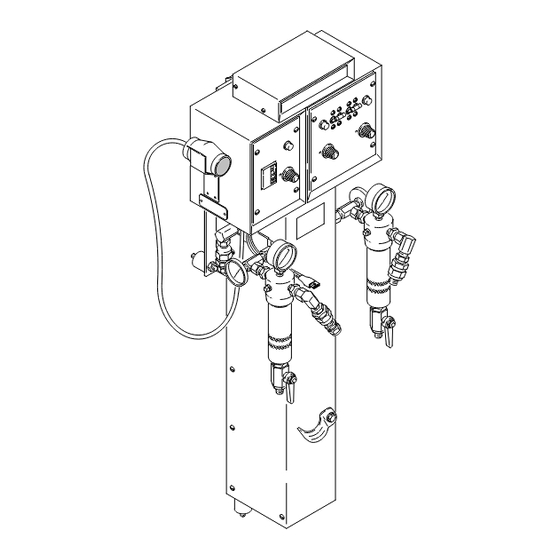
Page 7: Typical Installation
Installation Typical Installation This drawing shows all the components and recommended accessories for a Foam-Cat 400 Sprayer, Model 235260, and the correct routing of all air and fluid hoses. Foam-Cat Foam–Cat Heated Air Dryer Kit Hose Bulldogr Proportioning Feed Pump Pump 01688 Fluid Hose Displacement Pump... -
Page 8: Component Description
Installation Component Description Fluid heater and control The independent circuit breakers turn on or off the main electrical power from the junction box. The The fluid heater (G) is actually two separate heaters, heated hose circuit breaker (319) (Models 235259 and one for Resin and one for Isocyanate. - Page 9 Installation Component Description (continued) Thermometer gauges With the Heater TEMP SET at 115_F (46_C), and at an ambient temperature of 60_F (16_C), the heater Each heater has an independent thermometer (204). output automatically rises to 125_F (52_C). As the Because of the effect on the surrounding metal ambient temperature rises to 80_F (27_C), no exposed to the air, the thermometer usually reads far compensation is needed and the fluid is heated to just...
-
Page 10: How To Size A Generator
If you have purchased the heater module separately, bolt it securely to the Graco Pump Stand, part no. CAUTION 217296 (see manual 307551) or to a wall. A mounting hole diagram is on the back cover of manual 307551. -
Page 11: Flush The Heater
Installation Flush the Heater 3. Remove the outlet fittings (X) from both fluid filter outlet nipples (114). 4. Plug each outlet nipple (114) with a swivel (P/N WARNING 156173) and plug (P/N 101754). These parts are shown exploded on the left side of Fig. 4 and assembled on the right side of Fig. -
Page 12: Connect The Electrical Service
Installation Connect the Electrical Service The electrical requirements for the heater and heated WARNING hose controls and the wiring diagram are shown on the inside cover of the junction box (233). Wire the heater ELECTRIC SHOCK HAZARD to your electrical service. Three jumper wires are To reduce the risk of serious injury, included. -
Page 13: Ground The System
Installation Ground the System 4. Air hoses: use only Graco heated hose, which are WARNING electrically conductive. FIRE, EXPLOSION, AND ELECTRIC 5. Spray gun: obtain grounding through connection to SHOCK HAZARD a properly grounded fluid hose and pump. Before operating the heater, ground the system as explained below. -
Page 14: Prime The Heater
Installation Prime the Heater 8. Open the feed pump air valve. CAUTION 9. With the air or hydraulic power to the proportioning Prime the heater and sprayer with fluid before turning pump set at a low pressure, turn on the pump. on the heater to reduce the risk of overheating and burning out the heater element. -
Page 15: Connect The Hoses
Installation Connect the Hoses 10. Prime the Hoses 1. Tightly close the spray gun fluid valves and discon- WARNING nect the gun from its manifold. Refer to the gun manual. INJECTION HAZARD To reduce the risk of overpressurizing 2. Hold each side of the gun manifold over a sepa- the heater and pump, which can cause rate grounded waste container, open the fluid component rupture, serious injury or... -
Page 16: 11. Adjust The Heater
Installation 11. Adjust the Heater 1. Measure the incoming voltage on the junction box 7. If using a heated hose control, test the Ground power in terminal block from pins 1 to 2, pins 3 to Fault Interrupter (GFI) daily. To test, depress the 4, and pins 5 to 6. -
Page 17: Troubleshooting
Troubleshooting WARNING To reduce the risk of injury from burns or electric shock, never operate the heater with any heater shield or panel removed. Disconnect the main electrical power to the heater before removing any heater panels. To reduce the risk of serious injury, including injection, follow the Pressure Relief Procedure on page 6 before checking or repairing any part of the heater or spray system. -
Page 18: Heater
Troubleshooting Heater Problem Cause Solution Heater Control indicator lamp stays Flow rate too high to maintain set Decrease flow rate; using smaller orifice nozzle temperature reduces flow rate. Release gun trigger; lights should go off in a few seconds. Maximum flow rates are: Foam-Catr 200: 15 lb/min (6.8 kg/min) Foam-Catr 400: 30 lb/min (13.5 kg/min) Faulty Sensor Probe (256) - Page 19 Troubleshooting Problem Cause Solution Temperature erratic or inaccurate Sensor probe (256) out of position Probe must protrude 1.44” (36 mm) from manifold. See Fig. 16, page 27. Indicator light should go out within 5 seconds of shutting gun off after flowing. Heater out of calibration Calibrate controls.
-
Page 20: Electrical Resistance Checks
Troubleshooting Electrical Resistance Checks WARNING To reduce the risk of serious injury, including fluid Tool 110968 injection or electric shock: 1. Follow the Pressure Relief Proce- dure on page 6 before checking or adjusting any part of the system or any component and whenever you are instructed to relieve pressure. - Page 21 Troubleshooting – Electrical Resistance Checks Heater Wiring Schematics Heater No. 235840 is shown in Fig. 10. The wiring for Heater No. 235839 is identical except the second set of elements (wires 9, 10, 19, 20) are not used. POWER IN TERMINAL BLOCK (TB) RESIN HEATER LAMP...
-
Page 22: Optional Atc (Ambient Temperature Compensator)
Troubleshooting – Electrical Resistance Checks Optional ATC 4. Check the resistance across wires 7 and 8, and 9 and 10, on the RES board. Check the resistance (Ambient Temperature Compensator) across wires 17 and 18, and then 19 and 20 on the 1. -
Page 23: Hose Control Circuit Board
Troubleshooting – Electrical Resistance Checks POWER IN Hose Control Circuit Board TERMINAL BLOCK (TB) HOSE SENSOR SIMULATOR LAMP BOARD OPTIONAL ATC – – TRIAC TEMP DIAL M– OPTIONAL STANDARD CONNECTOR HOSE CONNECTOR 01690 Fig. 11 308219... -
Page 24: Triac
Troubleshooting – Electrical Resistance Checks Triac 3. Clamp the positive and negative meter leads to the pins indicated in the chart in Fig. 12. Replace the triac if any one of the readings is incorrect. 1. Follow the Setup instructions on page 20. NOTE: When using a digital V.O.M. -
Page 25: Service
(291 or 336) and the triac (281 or 306a). 2. Follow the Pressure Relief Proce- 4. Apply conductive paste (order Graco P/N 110009) dure on page 6 before checking or to the bottom flange of the new triac. Position the adjusting any part of the system or triac as shown in Fig. -
Page 26: Hi-Limit Thermostat
3. Disconnect the wires to the thermostat (252). See Fig. 14. 4. Remove the screws, lockwashers and the thermo- stat. 5. Apply conductive paste (order Graco P/N 110009) Hi-limit thermostat to the bottom flange of the new thermostat. reset button Fig. -
Page 27: Heater Sensor Probe
Service – Heater Sensor Probe 10. Guide the probe wires through the opening in the WARNING bottom of the control box. To reduce the risk of serious injury, including burns 11. Insert the new probe wires into the outer slots of from hot fluid or hot metal;... -
Page 28: Heater Element
Service – Heater Element NOTE: Refer to Fig. 17 except where noted. WARNING 1. Relieve the pressure, and shut off the main power To reduce the risk of serious injury, including burns to the heater. from hot fluid or hot metal; fluid injection; or electric shock: 2. - Page 29 Service – Heater Element NOTE: If replacing the rear element, go to Step 16. 16. Remove the control panel cover (216). Guide the wires of the heater up through the bottom of the control box. 13. If the front heater element was replaced, tighten the probe adapter (247c) just one turn.
-
Page 30: Circuit Board
Service – Circuit Board Replacing a Circuit Board Disassembly 1. Relieve the pressure, and shut off the main power WARNING to the heater. Have a person qualified in electrical 2. Remove the control panel cover (216 or 317). repair replace a circuit board. An incor- rectly installed circuit board can bypass 3. - Page 31 Heater No. 235840 is shown in Fig. 21. The wiring for Heater No. 235839 is identical except the second set of 1. Apply conductive paste (Graco P/N elements (wires 9, 10, 19, 20) are not used. 110009) to the bottom flange of the triac (223a or 306a).
-
Page 32: Calibrating The Controls
Service Calibrating the Controls Calibrating the Controls NOTE: The thermometers normally read very low during no-flow conditions. This is due to the influence of the metal surrounding the gauge which is exposed WARNING to the air. To reduce the risk of serious injury, including fluid 6. - Page 33 Notes 308219...
-
Page 34: Hose Sensor Simulator, Optional Atc
Connect one connector to each circuit board at Hose Sensor Simulator Calibration position J1 of the heater and hose controls. 1. A Graco heated hose (P/N 218613, 218614, 4. Tighten the cable clamp screws and reinstall the 947514, 947515 and 948723) must be connected control panel covers and junction box cover. - Page 35 Service – Hose Sensor Simulator, Optional ATC HOSE SENSOR LAMP SIMULATOR POWER IN TERMINAL BLOCK (TB) BOARD OPTIONAL – – TRIAC TEMP DIAL M– CONNECTOR STANDARD OPTIONAL HOSE CONNECTOR 01309 Fig. 23 308219...
-
Page 36: Parts
Parts – Heater Assembly 235259 Foam-Cat Heater, 15 lb/min (6.75 kg/min) 235260 Foam-Cat Heater, 30 lb/min (13.5 kg/min) 01302 Part No. Description Part No. Description 235256 CONTROL, heated hose 102814 GAUGE, pressure, fluid; 0–3000 psi 100188 NUT, heavy, hex, 5/16” (0–20.7 MPa, 0–207 bar) range 100214 LOCKWASHER... -
Page 37: Heated Hose Control
Parts – Heated Hose Control 235256 Foam-Cat Heated Hose Control NOTE: The control does not include wiring junction box (233) shown on page 38. 306a 01309 Part No. Description Part No. Description 188168 CLAMP, component 188060 PANEL, control 218655 SENSOR, hose simulator 100016 LOCKWASHER 100035... -
Page 38: Heater
Parts – Heater 235839 Foam-Cat Heater Assembly, 15 lb/min (6.75 kg/min) 235840 Foam-Cat Heater Assembly, 30 lb/min (13.5 kg/min) 223a 01298 Included with circuit board NOTE: For additional parts of Heater, see pages 39 and 40. Part No. Description Part No. Description 106501 CONNECTOR, electrical... - Page 39 Parts – Heater 235839 Foam-Cat Heater Assembly, 15 lb/min (6.75 kg/min) 235840 Foam-Cat Heater Assembly, 30 lb/min (13.5 kg/min) DETAIL NOTE: Use PTFE tape and sealant on pipe threads. 247d 247c 247b 247a Ref 243 01693 01297 NOTE: For additional heater parts, see pages 38 and 40. Part No.
- Page 40 Parts – Heater 235839 Foam-Cat Heater Assembly, 15 lb/min (6.75 kg/min) 235840 Foam-Cat Heater Assembly, 30 lb/min (13.5 kg/min) 01697 NOTE: For additional parts included in the Heater, see pages 38 and 39. Part No. Description Part No. Description 100642 CAPSCREW, hex hd;...
-
Page 41: Electrical Schematics
Electrical Schematics Model 235840 RESIN HEATER ISO HEATER TEMP TEMP FRONT FRONT REAR REAR 240V 240V M– M– TRIAC TRIAC SWITCH SWITCH OPTIONAL OPTIONAL STANDARD STANDARD LITE LITE OPTIONAL OPTIONAL 01299 Model 235839 RESIN HEATER ISO HEATER TEMP TEMP FRONT FRONT 240V 240V... -
Page 42: Dimensions
Dimensions 42” (1067 mm) Overall height 12.5” (318 mm) Overall depth 17” (432 mm) Overall width 8.1” (205 mm) 8.1” (205 mm) 5.1” (129 mm) 2.0” (51 mm) 8.6” (217 mm) 39.6” (1005 mm) 8.1” (205 mm) 6.1” (154 mm) 29.0”... -
Page 43: Technical Data
Technical Data Accessories Maximum Fluid Working Pressure ....3000 psi 110009 Conductive Paste (21 MPa, 210 bar) 217296 Pump Stand Fluid Temperature Operating Range . . . 95–158_F (35–70_C) Wetted Parts . -
Page 44: Graco Standard Warranty
With the exception of any special, extended, or limited warranty published by Graco, Graco will, for a period of twelve months from the date of sale, repair or replace any part of the equipment determined by Graco to be defective.
Need help?
Do you have a question about the FOAM-CAT 200 Series and is the answer not in the manual?
Questions and answers