Table of Contents
Advertisement
Quick Links
Instructions - Parts
Viscon
Fluid Heater
For variable heating of fluids.
Not approved for use in explosive atmospheres or hazardous locations.
Model No. 16T525
1750 W; 7.3 A; 240VAC; 50/60Hz, 1 Phase
2000 psi (14 MPa, 138 bar) Maximum Working Pressure
Important Safety Instructions
Read all warnings and instructions in this manual.
Save these instructions.
®
LT
3A2824B
EN
TI19998a
9902471
Conforms to
UL Std. 499
CSA Std. 22.2 No. 88
Advertisement
Table of Contents

Related Manuals for Graco Viscon LT


Summary of Contents for Graco Viscon LT
- Page 1 Instructions - Parts ® Viscon 3A2824B Fluid Heater For variable heating of fluids. Not approved for use in explosive atmospheres or hazardous locations. Model No. 16T525 1750 W; 7.3 A; 240VAC; 50/60Hz, 1 Phase 2000 psi (14 MPa, 138 bar) Maximum Working Pressure Important Safety Instructions Read all warnings and instructions in this manual.
-
Page 2: Table Of Contents
Dimensions ......21 Graco Standard Warranty ....22 Graco Information . -
Page 3: Warnings
Warnings Warnings The following warnings are for the setup, use, grounding, maintenance, and repair of this equipment. The exclama- tion point symbol alerts you to a general warning and the hazard symbols refer to procedure-specific risks. When these symbols appear in the body of this manual or on warning labels, refer back to these Warnings. Product-specific hazard symbols and warnings not covered in this section may appear throughout the body of this manual where applicable. - Page 4 Warnings WARNING TOXIC FLUID OR FUMES HAZARD Toxic fluids or fumes can cause serious injury or death if splashed in the eyes or on skin, inhaled, or swallowed. • Read MSDSs to know the specific hazards of the fluids you are using. •...
-
Page 5: Installation
Installation Installation Typical Installation Drawing The typical installation drawing is only a guide. Your Graco distributor can assist in designing your system. ti19999a Key: Bleed-type Master Air Valve Fluid Filter Director Valve Air Filter Drain Valve Drain Back Tube Air Regulator and Gauge... -
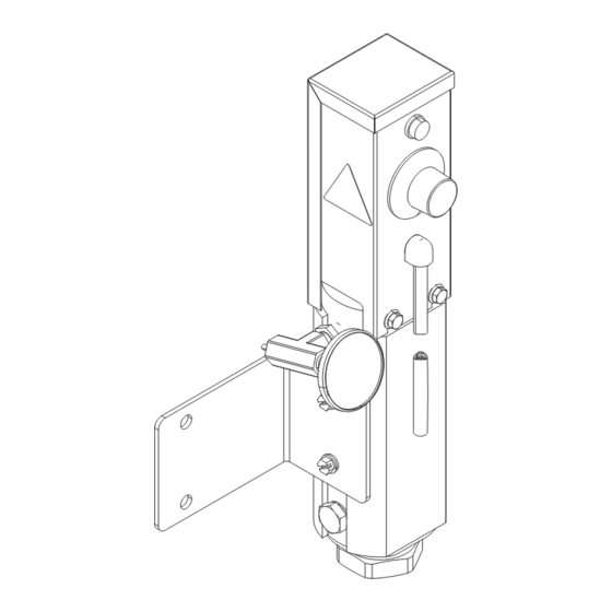
Page 6: Component Identification
Component Identification Component Identification ti19998a Key: AA Temperature control AE Outlet thermometer AB Heater light (illuminated while AF Mounting bracket heating) AG Heater plug AC Heater inlet, 3/8 npt(f) AH Insulating washers AD Heater outlet, 1/4 npt(f) . 2: Typical Installation – Heated Circulating System 3A2824B... -
Page 7: General Information
Component Identification Selecting Tubing General Information Fluid loses some heat through the tubing or hose between the heater and spray gun. Locate heater close to the spray area to minimize heat loss through plumb- • Select system components that meet temperature ing. -
Page 8: Mounting Heater
Component Identification Mounting Heater Heater controls must be easily accessible. The mounting surface must be able to support the weight of the heater and fluid, and any stress caused during operation. Wall Mounting Use included wall bracket 16R988 and insulating washers (29), part number 167002, quantity 2. -
Page 9: Fluid Connections And Accessories
Component Identification Fluid Connections and Accessories To prevent serious injury caused by component or equipment rupture: • Never install a shutoff device between the heater and gun as this will trap the heated fluid and not allow for expansion. • Never use a fluid regulator as a shutoff device if it is installed between the heater and gun •... -
Page 10: Electrical Connections
Component Identification Electrical Connections Power Cable Connections The heater power cable uses a 3 conductor cable and a NEMA L6-20P twist lock connector. If another connector is used, follow the table below for correct wiring. This equipment must be grounded. All electrical wiring Cable Color Code Function must be done by a qualified electrician and comply with... -
Page 11: Operation
Operation Operation Initial Flushing ressure Relief Procedure Follow the Pressure Relief Procedure whenever you see this symbol. To avoid skin injection, do not point gun at anyone or at any part of the body. To avoid fire and explosion, ensure main power is off and heater is cool before flushing. -
Page 12: Setting Heater Control
Operation Setting Heater Control (Refer to F . 6) 1. Set the heater control knob (9) to a trial setpoint of 4 or 5. 2. Start the pump and circulate fluid through the sys- tem at a very low flow rate of about 10-12 oz/min (0.30-0.35 liter/min). -
Page 13: Troubleshooting
Troubleshooting Troubleshooting PROBLEM CAUSE SOLUTION No heat and heater indicator light is Heater power off or circuit breaker Turn heater power on or reset circuit off. tripped. breaker. Bad thermostat (17). With power on, check for continuity on/off at clicks when turning the heater control knob. -
Page 14: Heater Temperature Controls
Repair Heater Temperature Controls See F . 7. Control knob (9) sets temperature of heater. Indicator light (8) turns on when thermostat is heating and off when heater reaches setpoint. Power in ti7008b 3A2824B... - Page 15 Repair Heater Cartridge Thermal Limit Sensor 1. See Before Beginning Repair, page 14. Relieve 1. See Before Beginning Repair, page 14. Relieve pressure. pressure. 2. Wait for heaters to cool. 2. Wait for heaters to cool. 3. Testing: Check that you have continuity across the 3.
- Page 16 Repair Indicator Light Heater Thermostat Switch 1. See Before Beginning Repair, page 14. Relieve 1. See Before Beginning Repair, page 14. Relieve pressure. pressure. 2. Wait for heaters to cool. 2. Wait for heaters to cool. 3. See F . 7. Loosen two screws (12) and remove 3.
- Page 17 Repair mostat switch from bracket. Pull thermostat Cleaning Heater Core probe (JJ) slowly out of heater core (2). 8. Insert new thermostat probe into core with heat sink compound 110009. Use screws (25) to install new thermostat switch behind bracket face and install control knob.
-
Page 18: Parts
Parts Parts Blue Brown Green/ Power from Brown Blue Green/ Yellow Control Box Yellow 240 V Lamp 240 V 1750 Watt Apply a thin film of heatsink compound (26). Bend tabs on thermostat away from each other after installing wire connectors so cover cannot contact wires. Stretch capillary coils (KK) down to contact top of core (2). -
Page 19: Accessories
Accessories Accessories Ref Part Description 24K987 HOUSING, heater 24K988 CORE, heater, spiral 110009 Heat sink compound, 1 oz. tube 24K992 INSULATOR, heater 101754 PLUG, pipe 24K991 BUSHING, reducing, 1-1/5 x 3/8 166863 FITTING, nipple, reducing 114286 LIGHT, indicator, 240V 24K979 KNOB, control, heater 119924 BUSHING, strain relief, 90 degree 16T187 HARNESS, power, heater SCREW, machine, hex serrated... -
Page 20: Technical Data
Technical Data Technical Data Maximum Working Pressure ..... . 2000 psi (140 bar, 14 MPa) Maximum Amps ....... . 7.3 A Maximum Fluid Temperature . -
Page 21: Dimensions
Technical Data Dimensions 2.9 in. 2.5 in. (7.3 cm) (6.35 cm) 15.3 in. (38.7 cm) 1/4 npsm Fluid Outlet 70 in. (178 cm) SJTO cable with NEMA L6-20P twist lock connector ti19998a 3/8 npt(f) Fluid Inlet 3A2824B... -
Page 22: Graco Standard Warranty
With the exception of any special, extended, or limited warranty published by Graco, Graco will, for a period of twelve months from the date of sale, repair or replace any part of the equipment determined by Graco to be defective.
Need help?
Do you have a question about the Viscon LT and is the answer not in the manual?
Questions and answers