
Related Manuals for Planet VIP-161W


Summary of Contents for Planet VIP-161W
- Page 1 Wireless Analog Telephone Adapter VIP-161W / VIP161SW User’s manual Version 1.0.0...
-
Page 2: Ce Mark Warning
Copyright Copyright (C) 2007 PLANET Technology Corp. All rights reserved. The products and programs described in this User’s Manual are licensed products of PLANET Technology, This User’s Manual contains proprietary information protected by copyright, and this User’s Manual and all accompanying hardware, software, and documentation are copyrighted. - Page 3 Revision User’s Manual for PLANET Wireless Analog Telephone Adapter: Model: WATA Rev: 1.0.0 (2007, August) Part No. EM-VIP_WATAV1...
-
Page 4: Table Of Contents
ABLE OF ONTENTS Chapter 1..........................7 Overview............................7 Package Content ..........................8 Physical Details ..........................9 LED Display................................10 Chapter 2..........................11 Physical Installation Requirement....................11 Hardware Installation............................11 Port Description..............................11 Installation ................................12 Wizard Setup................................13 Operation Mode ..............................13 Internet Setting Setup ............................15 NAT setting ................................17 VoIP Call Setup..............................18 Chapter 3.......................... - Page 5 Virtual Server setting (for AP mode)......................34 Port Trigger................................35 Packet Filter .................................36 URL Filter................................37 Security (For AP / AP & AP-Client mode)....................38 UPNP (For AP / AP & AP-Client mode).......................39 DDNS (For AP / AP & AP-Client mode).......................40 SNMP (For AP / AP & AP-Client mode) ......................41 QoS (VLAN) ................................42 Chapter 4..........................
- Page 6 Save & Logout ..............................66 Save Configurations ............................67 Save Configuration & Logout........................67 Save Configuration & Reboot........................67 Appendix A Voice Communication Samples .................68 Make a three - way conference call......................70 Appendix B Frequently Asked Questions List ..............71 Appendix C VIP-161W/VIP-161SW Specifications ..............72...
-
Page 7: Chapter 1
Combining the cutting edge of Internet telephony and ATA manufacturing experience, PLANET now introduces the latest member of PLANET Wireless ATA family: the VIP-161W/VIP-161SW. To bring the most satisfaction to customers, the WATA not only provides the high quality of voice communications and wired Internet sharing capabilities but also offers Access Point (AP) function for daily wireless communication. -
Page 8: Package Content
Product Features IEEE 802.11b/g compliant • Multi-mode: AP, AP-Client Mode • Smart QoS mechanism to ensure the voice quality • Auto-config feature for flexible, ease-of use system integration • NAT Router, Static Routing, Virtual Server, DMZ • Smart QoS mechanism to ensure the voice quality •... -
Page 9: Physical Details
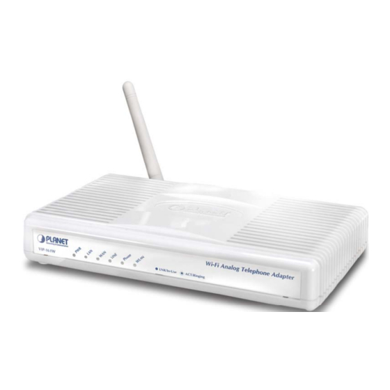
Physical Details The following figure illustrates the front/rear panel of WATA. Respective model/descriptions are shown below: VIP-161W: 1 FXS / 1 PTSN Wireless Analog Telephone Adapter. VIP-161SW: 2 FXS Wireless Analog Telephone Adapter Front Panel of VIP-161W Back Panel of VIP-161W... -
Page 10: Led Display
LED Display LED display of VIP-161W / VIP-161SW LED Indicators Descriptions On: WATA is power ON Off: WATA is power Off On: WATA network connection established Flashing: Data traffic on cable network Off: Waiting for network connection On: LAN is connected successfully... -
Page 11: Chapter 2
100BaseTX networks. FXS port can be connected to analog telephone sets or Trunk Phone Line of PBX. Line port can be connected to RJ11 PSTN line (VIP-161W Line only) Push this button until 3 seconds, and WATA will be set to Reset factory default configuration. -
Page 12: Installation
Installation 1 Connect the 12V DC IN to the power outlet with power adaptor. 2 Connect Line to PSTN. 3 Connect Phone to a telephone jack with the RJ-11 analog cable. Connecting to a PC 1 Connect the Ethernet cable (with RJ-45 connector) to any LAN port. 2 Connect the other end of the Ethernet cable to your PC’s installed network interface card (NIC). -
Page 13: Wizard Setup
In order to connect machine for administration, please locate Note your PC in the same network segment (192.168.0.x) of VIP-161W/VIP-161SW. If you’re not familiar with TCP/IP, please refer to related chapter on user’s manual CD or consult your network administrator for proper network configurations. - Page 14 Three WLAN modes of operation are available for Internet Access: AP Mode: In this mode the WATA supports AP functionality only. The WATA has the following network interfaces: WAN, LAN and Wireless LAN. AP-Client Mode: In this mode the WATA accesses a remote AP. Please be sure that you have an account to access your wireless service provider AP.
-
Page 15: Internet Setting Setup
Internet Setting Setup WAN Setting Network Address Translation (NAT) serves connecting multiple NAT Mode computers to the Internet using one IP address. Bridge mode serves to connect a local area network (LAN / Wireless) Bridge Mode to another local area network that uses the same protocol. Three methods are available for Internet Access. - Page 16 AP-Client Mode This paragraph defines the required parameters to set up the WLAN interface as a Client on your wireless access network. You need to define the following parameters: Default WLAN mode / Remote SSID / Authorization key / IP / Gateway. AP &...
-
Page 17: Nat Setting
Local SSID. NAT setting LAN IP Setting Private IP address for connecting to a local private LAN IP Address network. (Default: 192.168.0.1) Subnet mask for the local private network (Default: Subnet Mask 255.255.255.0) Enable to open LAN port DHCP server DHCP Server Assigned DHCP IP Address DHCP server range from start IP to end IP Client to ask DHCP server refresh time, range from 60 to... -
Page 18: Voip Call Setup
VoIP Call Setup Configure the numbering with phone/line ports SIP Proxy Server IP There is a SIP Proxy Server address and port fields. Check addresses with your ITSP provider. Pleae check with your ISP provider. Phone number / password Finishing the Wizard Setup After completing the Wizard Setup, please click “Finish”... -
Page 19: Chapter 3
Chapter 3 Network Service Configurations Configuring Netowrk setting for your Wi-Fi ATA The WATA integrates a web-based graphical user interface that can cover most configurations and machine status monitoring. Via standard web browser, you can configure and check machine status from anywhere around the world. -
Page 20: Static Ip
Static IP If you are a leased line user with a fixed IP address, enter in the IP address, subnet mask, gateway address, and DNS (domain name server) address(es) provided to you by your ISP. Each IP address entered in the fields must be in the appropriate IP form, which are four IP octets separated by a dot (x.x.x.x). -
Page 21: Host Name
Host Name The Host Name field is optional but may be required by some Internet Service Providers. The default host name is the model number of the device. I WAN Port MAC The MAC (Media Access Control) Address field is required by some Internet Service Providers (ISP). The default MAC address is set to the MAC address of the WAN interface in the device. -
Page 22: Dns Server
DNS Server DNS stands for Domain Name System. Every Internet host must have a unique IP address; also they may have a user-friendly, easy to remember name such as www.wata.com The DNS server converts the user-friendly name into its equivalent IP address. The original DNS specifications require that each domain name is served by at least 2 DNS servers for redundancy. -
Page 23: Wlan Setting
WLAN Setting A WLAN is a data communication system that reduces the need for a wired connection, thereby adding new flexibility and convenience to your network. Using electromagnetic waves, WLAN's transmits and receives data over the air, minimizing the need for wired connections and combines data connectivity with user mobility. - Page 24 devices is called a Selection channel. Select a channel ID that is not already in use by a neighboring device. When the users select this option, the WIFI-ATA automatically WLAN Frequency finds the channel with the least interference and uses that channel Auto for wireless ATA transmission.
- Page 25 AP-Client Only Mode In this mode the WATA is used to access the Wireless Service Provider network by connecting wirelessly to the remote (Outdoor AP). The user can access the PSTN network by connecting to the FXS ports or accessing the internet by connecting the PCs to the 2 Ethernet ports. Note When WATA operate in AP-Client Mode, the WAN and LAN RJ-45 interface will be configured as a 2 port switch for connecting...
- Page 26 Key in the W-LAN IP address, W-LAN Subnet mask and W-LAN Static IP Gateway from AP of WISP When the DHCP Client is enabled, the WIFI ATA will get the IP DHCP Client Address from Outdoor AP of WISP. Enter User Name / Password provided by your ISP, the WATA will PPPoE Client get the IP Address from Outdoor AP of WISP Define the same as your Wireless Router uses...
- Page 27 Example: AP & AP-Client Mode The WIFI ATA can operate in AP-Client and access to another (Outdoor) AP. The wireless client needs to have the same SSID, Channel, Encryption settings as the main AP. The user may need to change the default IP to avoid IP conflicts.
- Page 28 Note When WATA operates in AP-Client (or AP & AP-Client) Mode, the WAN and LAN RJ-45 interface will be configured as a 2 port switch for connecting with 2 PCs for access wireless network. For wireless connected type 802.11 B/G mixed/ 802.11b only / WLAN Mode 802.11G only Define the same as your Wireless Router uses...
- Page 29 Scan usable network:Select list to remote AP SSID (magnifying glass) Search remote AP list page Note After scan and select the Outdoor AP, the channel and encryption method should be identical with the remote AP Example:...
-
Page 30: Access Policy (For Ap And Ap& Ap-Client Mode Only)
Access Policy ( For AP and AP& AP-Client mode only) Access Policy: in WATA security, an access control list is a list of “allow all / Reject all" to an MAC. Access Control List:MAX MAC List:64. DHCP Server Setting DHCP stands for Dynamic Host Control Protocol. The DHCP server gives out IP addresses when a device is starting up and request an IP address to be logged on to the network. -
Page 31: Static Router
Enter the starting IP address for the DHCP server’s IP assignment Assigned DHCP IP and the ending IP address for the DHCP server’s IP assignment. Address Assign the length of time for the IP lease, default setting is 86400 DHCP IP Lease Time seconds. - Page 32 Enable/Disable the static route Enable Indicates the type of route as follows, Host for local connection and Net Type for network connection Defines the base IP address (Network Number) that will be compared with the destination IP address (after an AND with NetMask) to see if this Target is the target route The subnet mask that will be AND'd with the destination IP address and...
-
Page 33: Nat (For Ap / Ap-Client / Ap & Ap-Client Mode)
NAT (for AP / AP-Client / AP & AP-Client mode) NAT (Network Address Translation) serves three purposes: • Provides security by hiding internal IP addresses. Acts like firewall. • Enables a company to access internal IP addresses. Internal IP addresses that are only available within the company will not conflict with public IP. -
Page 34: Virtual Server Setting (For Ap Mode)
Force (IETF) standard that combines the best features of two existing tunneling protocols: Cisco's Layer 2 Forwarding (L2F) and Microsoft's Point-to-Point Tunneling Protocol (PPTP). L2TP is an extension to the Point-to-Point Protocol (PPP), which is an important component for VPNs. VPNs allow users and telecommuters to connect to their corporate intranets or extranets. -
Page 35: Port Trigger
Enable/Disable the virtual server mapping, default setting is Disable. Enable The port number on the WAN side that will be used to access the virtual service. Enter the WAN Port number, e.g. enter 80 to represent WAN Port the Web (http server), or enter 25 to represent SMTP (email server). Note: You can specify maximum 32 WAN Ports The protocol used for the virtual service. -
Page 36: Packet Filter
Enable / Disable the port trigger, default setting is Disable Enable This is the port used to trigger the application. It can be either a single port Trigger Port or a range of ports This is the protocol used to trigger the special application Trigger Type This is the port number on the WAN side that will be used to access the application. -
Page 37: Url Filter
The WAN IP port packet filter function, control a network IP port, default WAN / LAN setting is Enable Enable/Disable Enable/Disable the Internet to WAN IP source port rules, default setting is Enable Disabling This is the filter WAN IP address Source IP This is the port used for source IP service Dest. -
Page 38: Security (For Ap / Ap & Ap-Client Mode)
Enable/Disable the URL filter function, default setting is Disable Enable Enable/Disable Block URL to the client IP, default setting is Disable Enable This is the client IP is LAN address. Client IP This is the filter URL. URL Filter String Security (For AP / AP &... -
Page 39: Upnp (For Ap / Ap & Ap-Client Mode)
UPNP (For AP / AP & AP-Client mode) UPnP provides support for communication between control points and devices. The network media, the TCP/IP protocol suite and HTTP provide basic network connectivity and addressing needed. On top of these open, standard, Internet based protocols, UPnP defines a set of HTTP servers to handle discovery, description, control, events, and presentation. -
Page 40: Ddns (For Ap / Ap & Ap-Client Mode)
DDNS (For AP / AP & AP-Client mode) The DDNS (Dynamic DNS) service allows you to alias a dynamic IP address to a static hostname, allowing your computer to be more easily accessed from various locations on the Internet. When you want your internal server to be accessed by using DNS name rather than using the dynamic IP address, you can use the DDNS service. -
Page 41: Snmp (For Ap / Ap & Ap-Client Mode)
SNMP (For AP / AP & AP-Client mode) The simple network management protocol (SNMP) forms part of the internet protocol suite as defined by the Internet Engineering Task Force (IETF). SNMP is used by network management systems to monitor network-attached devices for conditions that warrant administrative attention. It consists of a set of standards for network management, including an Application Layer protocol, a database schema, and a set of data objects. -
Page 42: Qos (Vlan)
QoS (VLAN) VLAN which stands for Virtual LAN is defined in the IEEE802.1q. It is a technology allowing a company or an individual to extend their LAN over the WAN interface, breaching the physical limitations of regular LANs. Enable/Disable the QoS service, default setting is Disable Enable Set voice VLAN Priority 0 -7 ,Default is 1 Voice VLAN Priority... -
Page 43: Chapter 4
Chapter 4 Wireless Telephone Adapter Configurations SIP Configuration SIP is a request-response protocol, dealing with requests from clients and responses from servers. Participants are identified by SIP URLs. Requests can be sent through any transport protocol. SIP determines the end system to be used for the session, the communication media and media parameters, and the called party's desire to engage in the communication. - Page 44 Assign the SIP port number of Telephone adapter. Its range is 1024 to SIP Port Number 65535, default setting is 5060 SIP session refresh time interval. The time interval in which the phone periodically refresh SIP sessions by sending repeated INVITE or Update Session Timer request, depending on session type.
-
Page 45: Account Setting
TCP guarantees delivery of data and also guarantees that packets will be delivered in the same order in which they were sent SIP Time Interval SIP time interval in milliseconds. The default setting is 500 m-sec INVITE message timeout value. Assigns a value 1 to 100, default setting is 12 seconds. -
Page 46: Server Setting
Enter the password again, this is used to confirm user password for Confirmed Password authentication. Maximum 24 characters Enable/Disable, Support Remote-Party-ID header P-Asserted-Identity header—The present SIP implementation always derives the calling party number from the user name field of From header. P-Asserted But if P-Asserted-Identity header or Remote-Party-ID header is present in an incoming SIP INVITE message the user name should be derived from... - Page 47 SIP registration expired time. Assigns the time interval from 1 - 65535, Authentication Expired default setting is 3600 seconds Time Enable/Disable this flag for out-bound (out-session and in-session) Use Outbound Proxy for requests. Default setting is Disable All Messages Registrar Server Address Assigns the SIP Register Server’s IP address Port number of SIP Register Server.
-
Page 48: Nat Traversal
NAT Traversal STUN is a protocol for assisting devices behind a NAT firewall or router with their packet routing. STUN enables a device to find out its public IP address and the type of NAT service its sitting behind. When you enable the STUN function, you must input the STUN server address. UPnP: Enable/Disable Universal Plug and Play, default setting is Disable. -
Page 49: Echo Canceller
The Codec is used to compress the voice signal into data packets. Each Codec has different bandwidth requirement. There are 9 kinds of codec. To Codec Priority 1~9 determine the priority, selects one codec algorithm from the pull-down menus individually This defines the encoding rate for G723 Codec, default is 6.3Kbps Rate G.723 Rate RTP Payload length. -
Page 50: Dtmf Method
DTMF Method After the VoIP call is connected, when you dial a digit, this digit is sent to the other side by DTMF tone. There are two methods of sending the DTMF tone, In-band and Out-band. Choose “In-band” will send the DTMF tone in voice packet. -
Page 51: Call Service
Disconnect a call after not receiving RTP packet for this time value. RTP Timeout Assigns the time value from 1 to 100, default setting is 25 seconds Allowable the maximum percentage of RTP packet loss. Assigns the RTF Packet Lost percentage from 0 to 100, default setting is 20% Percentage Allowable the maximum number of consecutive ICMP destination... -
Page 52: Call Transfer Option
Call Transfer Option The Call Transfer Option feature which can enables a user to relocate an existing call to another telephone or attendants console by using the transfer button then dialing the required location. The transferred call is either announced or unannounced. Indicates whether the remote end is allowed to transfer the call to a third party. -
Page 53: Fxs Port Setting
Hot line:Enable / Disable, default setting is disable, this service allows you to make a call to a pre-programmed number by only lifting the handset. FXS Port Setting FXS (Foreign Exchange Station) is the interface on a VoIP device for connecting directly to telephones, fax MAChines, or similar device and supplies ring, voltage, and dial tone. - Page 54 There are two types to display the caller information on the screen. Before Ring, the caller id information is displayed before first ring. After Ring, the Caller ID Display caller id information is displayed between first ring and second ring. Default setting is Before Ring Type 1 alerting signal is used to detect CID when □device is ON-HOOK.
-
Page 55: Fax Setting
FAX Setting The T.38 FAX procedure is used for the changeover from VoIP to fax mode during a call. The SIP will establish a normal VoIP call using INVITEs with SDP field to support T.38 detail. T.38 Option:Select an option from the pull-down menu. Default setting is Voice. General Dialing Setting Inter-digit Timeout: If no other number is being dialed within this interval, the Telephony WATA will terminate this call. -
Page 56: Dialing Plan (Outgoing Mode)
Dialing Plan (Outgoing Mode) “Dialing plan” needs setting when the users use the method of Peer-to-Peer SIP VoIP call or SIP Proxy Server Mode. The SIP Dialing Plan has two kinds of directions: Outgoing (call out). Dial Plan (Outgoing): Peer-to-Peer Call Mode Registering to SIP Proxy Server Mode Note Press RESET in the “Dial Plan Configurations (Outgoing)”... - Page 57 1.08x leading call out, call to Destination IP address: 210.66.155.70 2.07x leading call out, call to Destination Domain Name: abc.dyndns.org Example_2 1. If user dial “100”, ATA automatically dial “0849103078” to Destination IP address 210.66.155.70 2. If user dial “101”, ATA automatically dial “0849103077”...
-
Page 58: Call Screen
Call Screen Call Screen allows you to block incoming or block outgoing calls from international number. Reject Incoming Phone Number:. Create and maintain a list of numbers to be screened. Incoming calls from the "screened callers" list will be blocked. Reject Outgoing Phone Number:. -
Page 59: Information
ToS=0x10 low delay ToS=0x08 high throughput ToS=0x04 high reliability ToS=0x02 ECT bit set ToS=0x01 CE bit set or set multiple bits, such as: (ToS=0x18) To set both low delay and high throughput. Information • System Information • Line Status System Information Click System Information to display system status, WAN type, LAN type and WLAN type. - Page 60 This system information page is “AP & AP-Client” Mode This system information page is “AP-Client” Mode.
-
Page 61: Line Status
Line Status This window displays the FXS ports and SIP registered status. Click on Refresh button to retrieve the status. Management • Administrator Account • Date/Time • PING Test • Save/Restore • Factory Default • Firmware Update • Auto Provision •... -
Page 62: Date/Time
Assign a name to represent the administrator account. Maximum 16 characters. Legal characters can be the upper letter “A” to “Z”, lower letter Administrator Name “a” to “z”, digit number “0” to “9” and an underscore sign¡ ”_”. The administrator name is case-sensitive. Note: the “blank” character is an illegal character Assign the administrator password. -
Page 63: Ping Test
Protocol used to help match your system clock with an accurate time NTP Time Server source. For example atomic clock or a server Choose your time zone, Default is (GMT+8:00) Beijing, Singapore, Taipei Time Zone Enable / Disable ,Default is Disable, time during which clocks are set one hour ahead of local standard time;... -
Page 64: Save/Restore
Save/Restore All settings can be saving to a local file. Or, you can upload a local file to restore as the device configuration for the Telephony WATA. Factory Default This function is used to restore all the parameters back to factory default setting. You can use the Save / Restore Setting (please refer to the section of "Save / Restore") to check the factory default configuration, after you click on the Set button. -
Page 65: Auto Provision
Auto Provision Enable or disable the auto-provisioning feature. If enabled WATA will try to download the configuration files from the provisioning server Execution Time:Default 1 hour (1 to 10 hours), WATA will try to download the configuration files from the provisioning server. Provision Server:Provision Server, default is empty. -
Page 66: Check Network Alive
Check Network Alive Use the Check Network Alive. Net valid node checking security feature to allow or deny access to server processes from network clients with specified IP addresses. Execution Time:5 ~ 55 min, default 10min Server 1 address:www.google.com Server 2 address:209.131.36.158 Save &... -
Page 67: Save Configurations
Save Configurations Save your WATA Setting after you setting finish. Save Configuration & Logout If you need to logout administrator right for web-access, please click the Logout link. The web system management interface will auto-logout with 1800 sec default value. Save Configuration &... -
Page 68: Appendix A Voice Communication Samples
Appendix A Voice Communication Samples There are several ways to make calls to desired destination in WATA. In this section, we’ll lead you step by step to establish your first voice communication via web browsers operations. • WATA to WATA connection via IP address (Peer-to-Peer mode) Assume there are two WATAs in the network the IP address are 172.16.0.1, 172.16.0.2 Analog telephone sets are connected to the phone (RJ-11) port of WATAs respectively WATA A. - Page 69 • Voice communication via IP PBX system ( IPX-2000) Registration / Registration / Authentication Authentication IPX-2000 IP address: 172.16.0.200 WATA AVIP-161W WAN IP address: 172.168.0.1 WATA B WAN IP address: 172.16.0.2 Line number: 1001 Line number: 2002 Device configurations on the WATA: STEP 1: Log in IPX-2000 and create two testing accounts/password: 1001/123 (for WATA A), and 2002/123 (for WATA B) for the voice calls.
-
Page 70: Make A Three - Way Conference Call
STEP 3: Please browse Server Setting menu and insert the proxy server IP address (or domain name) information obtained from your service provider. STEP 4: Repeat the same configuration steps on WATA B, and check the machine registration status, make sure the registrations are completed. Test the scenario: To verify the VoIP communication, please 1) Pick up the telephone on WATA A... -
Page 71: Appendix B Frequently Asked Questions List
Appendix B Frequently Asked Questions List Q: What is the default administrator password to login to the WATA? How to Login? A: By default, default username is “root” and no password to login to the router. For security, you should modify the password to protect your gateway against hacker attacks. Default WAN port IP address is “172.16.0.1”, LAN port IP address is “192.168.0.1”. -
Page 72: Appendix C Vip-161W/Vip-161Sw Specifications
Appendix C VIP-161W/VIP-161SW Specifications Product Wireless Analog Telephone Adapter Model VIP-161W VIP-161SW Hardware WLAN Standards IEEE 802.11 b/g Wireless Frequency 2.4GHz ~ 2.4835 GHz Range Security 64/128 bit WEP data encryption, WPA, WPA-PSK, WPA2, WPA2-PSK, WPA/WPA2 mix mode, WPAPSK/WPA2PSK mix mode.
Need help?
Do you have a question about the VIP-161W and is the answer not in the manual?
Questions and answers