Table of Contents
Advertisement
Copyright
Copyright (C) 2004 PLANET Technology Corp. All rights
reserved.
The products and programs described in this User's
Manual are licensed products of PLANET Technology,
This User's Manual contains proprietary information
protected by copyright, and this User's Manual and all
accompanying hardware, software, and documentation
are copyrighted.
No part of this User's Manual may be copied, photo-
copied, reproduced, translated, or reduced to any elec-
tronic medium or machine-readable form by any means
by electronic or mechanical. Including photocopying,
recording, or information storage and retrieval systems,
for any purpose other than the purchaser's personal
use, and without the prior express written permission of
PLANET Technology.
Disclaimer
PLANET Technology does not warrant that the hardware
will work properly in all environments and applications,
and makes no warranty and representation, either
implied or expressed, with respect to the quality, per-
formance, merchantability, or fitness for a particular
purpose.
PLANET has made every effort to ensure that this User's
Manual is accurate; PLANET disclaims liability for any
inaccuracies or omissions that may have occurred.
Information in this User's Manual is subject to change
without notice and does not represent a commitment on
the part of PLANET. PLANET assumes no responsibility
for any inaccuracies that may be contained in this User's
Manual. PLANET makes no commitment to update or
keep current the information in this User's Manual, and
reserves the right to make improvements to this User's
Manual and/or to the products described in this User's
Manual, at any time without notice.
If you find information in this manual that is incorrect,
misleading, or incomplete, we would appreciate your
comments and suggestions.
Advertisement
Table of Contents

Related Manuals for Planet POE-100


Summary of Contents for Planet POE-100
- Page 1 Copyright Copyright (C) 2004 PLANET Technology Corp. All rights reserved. The products and programs described in this User’s Manual are licensed products of PLANET Technology, This User’s Manual contains proprietary information protected by copyright, and this User’s Manual and all accompanying hardware, software, and documentation are copyrighted.
-
Page 2: Ce Mark Warning
Trademarks The PLANET logo is a trademark of PLANET Technology. This documentation may refer to numerous hardware and software products by their trade names. In most, if... -
Page 3: Table Of Contents
3.2 Technical Specification 3.3 Product Outlook Chapter 4 Hardware Installation 4.1 Prior installation 4.2 POE-100 – the injector installation 4.3 POE-100S – the splitter installation Appendix A RJ-45 pin assignment and cable system 11 A.1 Pin assignment A.2 Cable system... -
Page 4: Chapter 1 Introduction
Chapter 1 Introduction Thank you for purchasing our Power over Ethernet Adapter. This user's manual is to provide the installation and usage of this adapter for network installers and users. PLANET's PoE products include two models: Injector and Splitter. Injector inserts current into the unused wires in a standard network cable (pin: 4, 5, 7, 8). - Page 5 This page is intentionally left blank...
-
Page 6: Chapter 2 Package Contents
Package Contents Your Power over Ethernet Device contains the following in the package: Model: POE-100SK • Power over Ethernet Injector (POE-100) x 1 • Power over Ethernet Splitter (POE-100S) x 1 • Power Adapter x 1 • User’s Manual x 1 •... - Page 7 This page is intentionally left blank...
-
Page 8: Chapter 3 Features & Specifications
Ethernet data rate 10/100Mbps Power usage of Category 5 -: Pin 4, 5 pin assignment +: Pin 7, 8 (Ethernet + DC) Input voltage, current POE-100: 15VDC, 1A min. Output voltage, current POE-100S: DC 5V, 2A DC 7.5V, 1.5A DC 12V, 1A... -
Page 9: Product Outlook
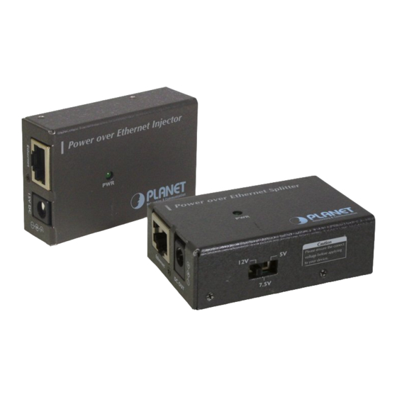
Number of Ethernet devices can be powered Ethernet data cable TIA/EIA-568, Category cable Dimensions (L x W x H) 64.5mm x 42.3mm x 20.4mm Operating Temperature 0~50 degree C environment Humidity 5~95%(non-condensing) 3.3 Product Outlook Figure 1: POE-100 Figure 2: POE-100S... -
Page 10: Chapter 4 Hardware Installation
DC power for this Ethernet Device conveniently and easily. The POE-100 comes with an AC-DC adapter with 15VDC output and injects this DC power into the un-used pin of the twisted pair cable (pair 4,5 and pair 7,8). -
Page 11: Poe-100 - The Injector Installation
Hint: SWITCH POE-100 Power over Ethernet Injector Paster Figure 3: Warning paster location 4. Connect the AC adapter to “15V DC” of POE-100. The power LED will be steady on. -
Page 12: Poe-100S - The Splitter Installation
(i.e. PWR LED is steady light green) Caution: Figure 4: Output voltage switch on POE-100S 2. Connect a standard network cable from “Ethernet+DC” of POE-100 to “Ethernet+DC” of POE-100S. The power LED of POE-100S will be steady on. Figure 5: Connection to POE-100S... - Page 13 Do not connect the cable from “Ethernet + DC” of POE-100 to re- mote device, otherwise the inner component Warning: of remote device may permanently malfunc- tion. 3. Connect the UTP cable in the package from “Ethernet” of POE-100S to the RJ-45 port of remote device.
-
Page 14: Appendix A Rj-45 Pin Assignment And Cable System
Appendix A RJ-45 pin assignment and cable system A.1 Pin assignment The following table and diagram show the standard RJ-45 receptacle/ connector and their pin assignments: RJ-45 Connector pin assignment MDI-X Contact Media Media Dependant Dependant Interface Interface -Cross TX + (transmit) Rx + (receive) TX - (transmit) Rx - (receive) -
Page 15: Cable System
100 products since pair 4,5 and pair 7, Remark: 8 are all being used. Only 10Base-T and 100Base-TX can apply with POE-100/ 100S products. A.2 Cable system The standard RJ-45 receptacle/connector There are 8 wires on a standard UTP/STP cable and each wire is color-coded. -
Page 16: Appendix B Frequently Asked Question
Connects the remote device to POE-100S, both power plug cable and Ethernet cable c. Plug-in the 15VDC power to the POE-100 and check the LED on it. d. Plug-in the UTP cable from POE-100 into the “Ethernet + DC”... - Page 17 IEEE802.3af de- vices. b. For POE-100 it will inject power all the time. This means it will send power once it is connect with 15VDC AC adapter. So, please DO NOT connect the UTP cable from POE-100’s “Ethernet+DC”...
- Page 19 Part No.:2010-000016-101...
Need help?
Do you have a question about the POE-100 and is the answer not in the manual?
Questions and answers