Advertisement
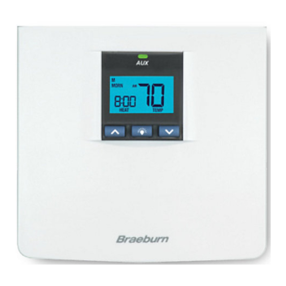
5100
OWNERS MANUAL
Compatible with low voltage multi-stage heat /
cool systems with up to two stages of heating
and two stages of cooling.
READ ALL INSTRUCTIONS BEFORE PROCEEDING
YEAR
LIMITED
WARRANTY
Store this
booklet for
future reference
Braeburn Systems LLC, as an Energy Star partner
has determined that this product meets the Energy
Star Guidelines developed by the U.S. Environmental
Protection Agency & the U.S. Department of Energy
for maximum energy efficiency.
© 2004 Braeburn Systems LLC All Rights Reserved.
Premier Series
7-Day Programmable
2-Heat / 2-Cool Heat / Cool
Digital Thermostat
Pub. No. 5100-100-002
Quick Reference/Installation Guide
CONTENTS
FEATURES
1
2
SPECIFICATIONS
INSTALLATION
3
Replacing Existing Thermostat
3.1
Installing Your New Thermostat
3.2
TESTING YOUR NEW THERMOSTAT
4
PROGRAMMING
5
Default Thermostat Settings
5.1
Setting Current Time of Day and Day of Week
5.2
Setting Temperature Differential and Residual
5.3
Cooling Fan Feature
Setting First Stage Differential
5.3.1
Setting Second Stage Differential
5.3.2
Setting Residual Cooling Fan Feature
5.3.3
Setting Your Energy Saving Programs
5.4
Tips Before Starting
5.4.1
Using Quick Program Groups
5.4.2
or Individual Day Programming
Entering Your Program
5.4.3
6
ADDITIONAL OPERATION FEATURES
Review Set Temperature
6.1
Temporary Program Override
6.2
Permanent Hold (Vacation) Mode
6.3
Efficient Recovery Mode (ERM ™ )
6.4
6.5
Compressor Protection
High Temperature Safety Switch
6.6
Changing Fahrenheit (˚F) to Celsius (˚C)
6.7
Low Battery Detection and Replacement
6.8
Replacing the Back-up Batteries
6.8.1
Resetting Thermostat
6.9
6.10
LED Status Indicator
TROUBLESHOOTING
7
8
WIRING DIAGRAMS
WARNING!
Important Safety Information
• Always turn off power to the air conditioning or heating system prior to installing,
removing, cleaning or servicing thermostat.
• Read this manual thoroughly prior to installing, programming or operating this
thermostat.
• This thermostat is designed for use with a 24 Volt AC low voltage multi-stage
heat / cool system.
• Do not use this thermostat on systems with voltages higher than 30 Volt AC.
• This thermostat requires 24 Volt AC power for normal operation and control of the
heating or cooling system.
• This thermostat also requires two (2) properly installed "AA" alkaline batteries to
retain user settings and programs in the event of loss of AC Power due to power
outage or rolling blackouts.
• Wiring must conform to all building codes and ordinances as required by local
and national code authorities having jurisdiction.
• Do not short (or jumper) across terminals on the gas valve or at the heating or
cooling system control board to test the thermostat installation. This could
damage the thermostat and void the warranty.
• Do not select COOL mode of operation if the outside temperature is below 50˚ F
(10˚ C). This could possibly damage the controlled cooling system and may cause
personal injury.
• This thermostat should only be used as described in this manual. Any other use
is not recommended and will void the warranty.
1
Advertisement
Table of Contents

Related Manuals for Braeburn 5100


Summary of Contents for Braeburn 5100
- Page 1 • Do not select COOL mode of operation if the outside temperature is below 50˚ F (10˚ C). This could possibly damage the controlled cooling system and may cause Braeburn Systems LLC, as an Energy Star partner personal injury. has determined that this product meets the Energy •...
-
Page 2: Installation
FEATURES INSTALLATION cont. • Contemporary styling with large display • 7 Day Programming Flexibility • AC Powered with Battery Back-up (2 AA Alkaline batteries included) • Relay Outputs for Maximum Compatibility • Easy Access Front Battery Door • Pre-programmed for quick installation •... -
Page 3: Testing Your New Thermostat
TESTING YOUR INSTALLATION NEW THERMOSTAT cont. cont. Installing Your New Thermostat cont. 6. Press the button on the keypad until the setpoint temperature is a minimum of 3 degrees lower than the current room temperature. 13. Turn on the front thermostat body over exposing the rear view of the circuit board. 7. - Page 4 PROGRAMMING PROGRAMMING cont. cont. Setting Temperature Differential and Residual Setting Residual Cooling Fan Feature 5.3.3 Cooling Fan Feature The default setting is 60 seconds. During the COOL mode of normal operation the fan will stay The default settings for the first and second stage differentials and residual cooling fan delay on for 60 seconds after the cooling system has satisfied the setpoint temperature and has turned settings are compatible with most systems and applications.
-
Page 5: Programming
PROGRAMMING PROGRAMMING cont. cont. Using Quick Program Groups or Individual Day Programming 5.4.2 Entering Your Program 5.4.3 You can select one of three Quick Program Groups or Individual Day programming to allow you 1. Place the system switch in the HEAT mode of operation. The display will show HEAT. to change the daily setpoint times and temperatures to meet your individual schedule needs. - Page 6 ADDITIONAL PROGRAMMING OPERATION FEATURES cont. cont. Efficient Recovery Mode (ERM™) 8. Place the system switch in the COOL mode of operation. The display will show COOL. Follow steps 2 through 6 to program the setpoint times and temperatures for the Quick Program This thermostat is equipped with a special feature to maximize your energy savings by Group or Individual Day selection for the COOL mode.
-
Page 7: Troubleshooting
ADDITIONAL TROUBLESHOOTING OPERATION FEATURES cont. cont. NOTE: Resetting the thermostat by pressing the RESET button will erase all entered SYMPTOM POTENTIAL SOLUTION programs, current time of day, day of week and other user settings. This will return all Thermostat settings to their default values. Changing ˚F / ˚C temperature Check to see if OFF is shown in display. -
Page 8: Setting Residual Cooling Fan Feature
TROUBLESHOOTING TROUBLESHOOTING cont. con. SYMPTOM POTENTIAL SOLUTION SYMPTOM POTENTIAL SOLUTION Replace back-up batteries as soon as possible. Low Battery Indicator LO is shown in the The temperature sensed by the thermostat is lower than the 40˚ See Low Battery Detection and Replacement section of this is shown in F (5˚... -
Page 9: Wiring Diagrams
Braeburn installation and operating instructions. Braeburn Systems LLC agrees to repair or replace at its option any Braeburn thermostat under warranty provided it is returned postage prepaid to our warranty facility in a padded carton within the warranty period, with proof of the original date of purchase and a brief description of the malfunction.
Need help?
Do you have a question about the 5100 and is the answer not in the manual?
Questions and answers