Table of Contents
Advertisement
Quick Links
Advertisement
Table of Contents

Related Manuals for Crestron V24-IMCW-C


Summary of Contents for Crestron V24-IMCW-C
- Page 1 Crestron V24-IMCW-C Interface Module for V24R-C and V24RL-C Installation Guide...
-
Page 2: Regulatory Compliance
This document was prepared and written by the Technical Documentation department at: Regulatory Compliance As of the date of manufacture, the V24-IMCW-C has been tested and found to comply with specifications for CE marking and standards per EMC and Radiocommunications Compliance Labelling. -
Page 3: Table Of Contents
Crestron V24-IMCW-C Interface Module for V24R-C and V24RL-C Contents Interface Module for V24R-C and V24RL-C: V24-IMCW-C Introduction ..........................1 Features and Functions ....................2 Specifications ......................2 Physical Description....................3 Setup ............................7 Network Wiring......................7 Supplied Hardware ...................... 8 Installation ........................ -
Page 5: Interface Module For V24R-C And V24Rl-C: V24-Imcw-C
Interface Module for V24R-C and V24RL-C: V24-IMCW-C Introduction The V24-IMCW-C is an interface module designed for use with a V24R-C or V24RL-C V-Panel™ 24” HD Touch Screen Display. It affords a convenient, pluggable connection for the touch screen, providing front panel jacks for DigitalMedia 8G+™ (DM 8G+™) and power. -
Page 6: Features And Functions
• Includes inserts to match black, white or almond faceplates • Includes surface mount and rack rail installation options • Provides pass-through connections for 24VDC power and DigitalMedia 8G+ Specifications Specifications for the V24-IMCW-C are listed in the following table. V24-IMCW-C Specifications SPECIFICATION DETAILS Power Requirements Power Pack 3.7 Amps @ 24 VDC... -
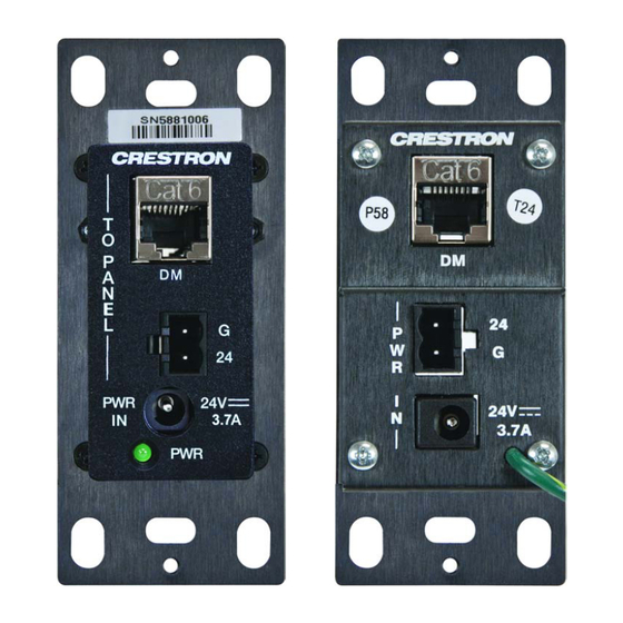
Page 7: Physical Description
1.58 in (40 mm) Weight 5 oz (141 g) with bracket Physical Description This section provides information on the connections, controls and indicators available on the V24-IMCW-C. V24-IMCW-C Physical View (Front and Rear) Interface Module: V24-IMCW-C • 3 Installation Guide – DOC. 7175C... - Page 8 (68 mm) 0.10 in (3 mm) 0.06 in (2 mm) 1.04 in (27 mm) 1.45 in (37 mm) 6.00 in 1.38 in (153 mm) (35 mm) 1.58 in (40 mm) 4 • Interface Module: V24-IMCW-C Installation Guide – DOC. 7175C...
- Page 9 (1) 2.1 x 5.5 mm DC power 24VDC 3.7A connector; 24 Volt DC power input from power pack PWR LED (1) Green LED, indicates DC power supplied from power pack (Continued on following page) Interface Module: V24-IMCW-C • 5 Installation Guide – DOC. 7175C...
- Page 10 1. An interface connector for the PWR IN 24, G port is provided with the unit. 2. Item(s) sold separately or included with touch screen display. 3. For DM 8G+ wiring, use Crestron DM-CBL-8G DigitalMedia 8G cable or generic CAT5e (or better) UTP or STP. Maximum wire length for DM 8G+ is 330 feet (100 meters) between devices.
-
Page 11: Setup
• Use Crestron power supplies for Crestron equipment. • Provide sufficient power to the system. • For DM 8G+ wiring, use Crestron DM-CBL-8G DigitalMedia 8G™ cable or generic CAT5e (or better) UTP or STP. Maximum wire length for DM 8G+ is 330 feet (100 meters) between devices. -
Page 12: Supplied Hardware
Interface Module for V24R-C and V24RL-C Crestron V24-IMCW-C Supplied Hardware The hardware supplied with the V24-IMCW-C is listed in the following table. Supplied Hardware for the V24-IMCW-C DESCRIPTION PART NUMBER Assy, Insert, Black 4513890 Assy, Insert, White 4513789 Assy, Insert, Almond... -
Page 13: Installation
Crestron V24-IMCW-C Interface Module for V24R-C and V24RL-C Installation The V24-IMCW-C can be installed in either a 1-gang box, rack mounted or mounted to any flat surface using the provided surface mount bracket. Installing in To install the V24-IMCW-C in a 1-gang box, ensure the unit is 1-Gang Box mounted into the electrical box as shown in the following illustration. - Page 14 Interface Module for V24R-C and V24RL-C Crestron V24-IMCW-C Rack The V24-IMCW-C can be mounted in a rack with other equipment Mounting using two of the four mounting holes on the corners of the interface module, as shown in the following illustration.
-
Page 15: Hardware Hookup
Crestron V24-IMCW-C Interface Module for V24R-C and V24RL-C Installing on To prepare the V24-IMCW-C to be mounted onto a level surface, a Level ensure the unit is attached to the surface mount bracket, as shown in Surface the following illustration. - Page 16 PWR IN – 24VDC 3.7A: From DC Power Pack CAUTION: The V24-IMCW-C can be powered via the 24 G 2-pin connection on the rear of the unit or the 24VDC 3.7A jacks on either the front or the rear of the unit. To avoid possible damage to the unit, use only one of these connectors.
-
Page 17: Problem Solving
Crestron V24-IMCW-C Interface Module for V24R-C and V24RL-C Problem Solving Troubleshooting The following table provides corrective action for possible trouble situations. If further assistance is required, please contact a Crestron customer service representative. V24-IMCW-C Troubleshooting TROUBLE POSSIBLE CORRECTIVE CAUSE(S) ACTION... -
Page 18: Further Inquiries
Crestron Web site (www.crestron.com/offices) for assistance within a particular geographic region. To post a question about Crestron products, log onto the Online Help section of the Crestron Web site (www.crestron.com/onlinehelp). First-time users must establish a user account to fully benefit from all available features. -
Page 19: Return And Warranty Policies
(property or economic damages inclusive) arising from the sale or use of this equipment. Crestron is not liable for any claim made by a third party or made by the purchaser for a third party. - Page 20 Crestron Electronics, Inc. Installation Guide – DOC. 7175C 15 Volvo Drive Rockleigh, NJ 07647 (2030554) Tel: 888.CRESTRON 09.12 Fax: 201.767.7576 Specifications subject to www.crestron.com change without notice.
Need help?
Do you have a question about the V24-IMCW-C and is the answer not in the manual?
Questions and answers