Table of Contents
Advertisement
Quick Links
SNAP PAC R-SERIES CONTROLLER
USER'S GUIDE
SNAP-PAC-R1
SNAP-PAC-R2
SNAP-PAC-R1-FM
SNAP-PAC-R2-FM
SNAP-PAC-R1-W
SNAP-PAC-R2-W
Form 1595-100826—August 2010
43044 Business Park Drive
Phone: 800-321-OPTO (6786) or 951-695-3000
Fax: 800-832-OPTO (6786) or 951-695-2712
www.opto22.com
Product Support Services
800-TEK-OPTO (835-6786) or 951-695-3080
Fax: 951-695-3017
Email: support@opto22.com
Web: support.opto22.com
Temecula
CA 92590-3614
•
•
Advertisement
Table of Contents
Troubleshooting

Related Manuals for OPTO 22 SNAP-PAC-R1


Summary of Contents for OPTO 22 SNAP-PAC-R1
- Page 1 SNAP PAC R-SERIES CONTROLLER USER’S GUIDE SNAP-PAC-R1 SNAP-PAC-R2 SNAP-PAC-R1-FM SNAP-PAC-R2-FM SNAP-PAC-R1-W SNAP-PAC-R2-W Form 1595-100826—August 2010 43044 Business Park Drive Temecula CA 92590-3614 • • Phone: 800-321-OPTO (6786) or 951-695-3000 Fax: 800-832-OPTO (6786) or 951-695-2712 www.opto22.com Product Support Services 800-TEK-OPTO (835-6786) or 951-695-3080 Fax: 951-695-3017 Email: support@opto22.com...
- Page 2 This warranty is limited to the original cost of the unit only and does not cover installation, labor, or any other contingent costs. Opto 22 I/O modules and solid-state relays with date codes of 1/96 or later are guaranteed for life.
-
Page 3: Table Of Contents
Table of Contents Chapter 1: Overview ........... . 1 Introduction. - Page 4 Chapter 3: System Information ......... 17 Communication Options .
- Page 5 SNAP-PAC-R1 and -R2 Comparison Chart ........
- Page 6 SNAP Analog Troubleshooting ............74 Appendix: SNAP Mounting Racks and Power Supplies .
-
Page 7: Chapter 1: Overview
Six models of the SNAP PAC R-series controller are available: • SNAP-PAC-R1, SNAP-PAC-R1-FM, and SNAP-PAC-R1-W each control a mix of SNAP analog, digital (both standard and high-density), and serial modules. Full digital functions include high-speed counting, quadrature counting, pulse measurement, and period and frequency measurement. -
Page 8: Ethernet Communication
INTRODUCTION Built-in functions and comparisons of the SNAP-PAC-R1 and SNAP-PAC-R2 are shown in the table on page Ethernet Communication All SNAP PAC R-series controllers communicate over standard 10/100 Mbps Ethernet networks and can be attached to an existing network. The controllers can also be used in an independent control network built with standard, off-the-shelf Ethernet hardware. -
Page 9: Serial Communication
NOTE: The R-series controller does not include an RS-485 port and cannot be used to control Opto 22 serial I/O processors, such as the SNAP PAC SB-series brains. Use an S-series controller for serial brains. -
Page 10: Software Availability
I/O. Software Availability PAC Project Basic is included with SNAP PAC controllers and is a free download from the Opto 22 website. PAC Project Professional is available for purchase on our website. To get it immediately, you can buy and download the software from the Opto 22 website at www.opto22.com;... -
Page 11: Related Documentation
EtherNet/IP for SNAP PAC Protocol Guide, form #1770. The following sections are included in this user’s guide: Chapter 1: Overview—information about the guide and how to reach Opto 22 Product Support. Chapter 2: Installation—quick-start steps to get SNAP PAC R-series controllers up and running quickly. -
Page 12: For Help
FOR HELP For Help If you have problems installing or using SNAP PAC R-series controllers and cannot find the help you need in this guide or on our website, contact Opto 22 Product Support. Phone: 800-TEK-OPTO (835-6786) 951-695-3080 NOTE: Email messages and... -
Page 13: Chapter 2: Installation
Chapter 2 2: Installation If you already know how you will use the SNAP PAC R-series controller and want to get it running quickly, follow the sections in this chapter. To learn about communication options and networking, start on page 17. -
Page 14: Installing Hardware
INSTALLING HARDWARE NOTE: If you run PAC Project applications in Microsoft Windows XP, make sure you have Service Pack 3 installed. Otherwise, a Microsoft bug may cause the system to crash. See OptoKB article #KB49838 details. Installing Hardware Assemble the rack and power supply according to the directions that came with them. For help with wiring, see the product data sheets, which are available on our website at www.opto22.com. -
Page 15: Removing A Module
CHAPTER 2: INSTALLATION 3. With the module correctly aligned Module keys over the connector, push on the module to snap it into place. When positioning modules next to each other, be sure to align the male and female module keys (shown in the detailed view in the illustration at right) before snapping a module into position. -
Page 16: Installing The Controller
75) for information on power supplies and wiring. 8. Before turning on power to the rack, follow instructions in Opto 22 form #1704, the PAC Manager User’ s Guide, to assign an IP address to the controller (required for both standard and wired+wireless models). -
Page 17: What's Next
To communicate with an Allen-Bradley Logix PLC or other system using EtherNet/IP, see the EtherNet/IP for SNAP PAC Protocol Guide, form #1770. To program your own applications, see Opto 22 form #1465, the OptoMMP Protocol Guide. Configuring I/O No matter how you communicate with SNAP PAC R-series controllers, you will need to configure I/O points and controller features. -
Page 18: Using Ppp Over A Modem
USING PPP OVER A MODEM Choose your configuration tool based on what you need to do: Use PAC Control for I/O configuration if… Use PAC Manager for I/O configuration if… • You have only one I/O unit or I/O unit •... -
Page 19: Configuring Ppp On The Controller
Configuring PPP on the Controller To configure PPP on the SNAP PAC R-series controller, see instructions in Opto 22 form #1704, the PAC Manager User’ s Guide. Also use this guide to assign an IP address to the Ethernet ports, configure points, and store configuration to flash. -
Page 20: Configuring Microsoft Windows Dial-Up Networking On Windows Xp
USING PPP OVER A MODEM NOTE: Configuration settings must be stored to the modem’ s NVRAM so they will be loaded when the SNAP PAC R-series controller sends a reset command to the modem. 3. If PCs will dial up the controller, set up Windows dial-up networking on the PCs that will call the controller. - Page 21 CHAPTER 2: INSTALLATION Options Tab Security Tab SNAP PAC R-Series Controller User’s Guide...
- Page 22 USING PPP OVER A MODEM Networking Tab Advanced Tab SNAP PAC R-Series Controller User’s Guide...
-
Page 23: Chapter 3: System Information
Networking..............Specifications, Connectors, and Dimensions ..Information on Features ..........SNAP-PAC-R1 and -R2 Comparison Chart ....Communication Options SNAP PAC R-series controllers communicate using TCP/IP or UDP/IP over a wired or wireless network. Physical Layer—All SNAP PAC R-series controllers communicate over a 10- or 100-Mbps wired Ethernet link. -
Page 24: Simultaneous Communication
COMMUNICATION OPTIONS • Custom software applications are easy to develop using our OptoMMP Communication Toolkit with ActiveX components and C++ classes. They use an IEEE 1394-based protocol to read and write to SNAP PAC R-series controllers. For developers not using Microsoft Windows, our IEEE 1394-based protocol is open and documented. -
Page 25: Accessing Snap R-Series Controllers Over The Internet
IEEE 1394-based For Communication Toolkit or IEEE 1394-based protocol, enterprise management system. protocol see OptoMMP Protocol Guide. Give technicians an Opto 22 PAC Display See PAC Display User’s Guide. HMI with alarming and trending. Monitor and control SNAP PAC PAC Control... -
Page 26: System Architecture
User’s Guide and OptoOPCServer User’s Guide. software such as HMIs. Write your own software applica- C++ or Active X: Opto 22’s IEEE See OptoMMP Protocol Guide. tion to communicate with the OptoMMP Com- 1394-based proto- system. -
Page 27: The I/O Side Of The Controller
Protocol Guide. The Control Side of the Controller The control side of the controller is like a traditional Opto 22 industrial controller. In the control side, the controller runs PAC Control flowcharts. These flowcharts provide the logic that controls processes through the system. -
Page 28: Using Data For Peer-To-Peer Communication
SYSTEM ARCHITECTURE (For information on using PAC Control, see form #1700, the PAC Control User’ s Guide, and form #1701, the PAC Control Command Reference.) You use PAC Control on a PC connected to the network, so you can create your control strategy and download it to the controller. - Page 29 CHAPTER 3: SYSTEM INFORMATION Scratch Pad areas within the SNAP PAC R-series controller’s memory map provide a way for other devices on the Ethernet network to access data in the controller. For descriptions of the Scratch Pad areas—bits, integers, floats, and strings—see the PAC Manager User’s Guide. For help in using PAC Control commands to access Scratch Pad areas, see “I/O Unit—Scratch Pad Commands”...
-
Page 30: Communicating With Enterprise Systems And Third-Party Software
SYSTEM ARCHITECTURE Communicating with Enterprise Systems and Third-Party Software In addition to its capabilities in I/O, control, and peer-to-peer communication, the SNAP PAC R-series I/O system can also interface directly with enterprise systems and third-party software that need to use its data. The following graphic shows how these software applications (and some hardware, too) can directly access the memory map in the controller’s I/O side for both I/O point data and strategy variable data. -
Page 31: The Complete System
CHAPTER 3: SYSTEM INFORMATION The Complete System When all these capabilities we’ve discussed are put together, you can see the versatility—and the wealth of applications—of the SNAP PAC R-series I/O system, shown below. SNAP PAC R-Series Controller User’s Guide... -
Page 32: Networking
NETWORKING Networking From a physical standpoint, SNAP PAC R-series controllers can be networked in several ways: • Connected directly to a PC or controller using a crossover cable • Attached to an existing TCP/IP Ethernet network • As part of an independent network built with standard Ethernet hardware •... -
Page 33: Attaching The Controller To An Existing Ethernet Network
CHAPTER 3: SYSTEM INFORMATION NOTE: Make sure you put 3 and 6 on the same pair, or you may experience noise and distance limitations. Also, make sure to include all pairs, since they are required for 100 Mbps. Attaching the Controller to an Existing Ethernet Network The first rule in attaching SNAP PAC R-series controllers to an existing network is to work closely with your system administrator, who must determine network topology and hardware. -
Page 34: Using The Controller In An Independent Network
NETWORKING diagram on page 31. (This implementation requires PAC Project Professional. For more information, see the SNAP PAC R-series data sheet, form #1594 and the SNAP PAC S-series data sheet, form #1584.) Or you might consider using a router, network switch, or other gateway device. NOTE: If you are using wired+wireless models, one of the segmented networks can be a wireless LAN. -
Page 35: Using The Controller In A Wireless Lan
CHAPTER 3: SYSTEM INFORMATION Using the Controller in a Wireless LAN A Wired+Wireless PAC-R (SNAP-PAC-R1-W or SNAP-PAC-R2-W) can also be used in a wireless local area network (LAN) built with components that meet 802.11a, b, or g standards, depending on which works best for your environment. -
Page 36: Network Segmenting: Wired And Wireless Networks
NETWORKING Network Segmenting: Wired and Wireless Networks The network shown in this diagram requires a Wired+Wireless R-series controller (SNAP-PAC-R1-W or SNAP-PAC-R2-W). The PAC runs a PAC Control strategy and controls one or more remote I/O units via a wireless access point. The controller is also connected to a separate, wired enterprise network through one of its wired Ethernet network interfaces. -
Page 37: Network Segmenting: Ethernet Connections To Host And I/O Units
Network Segmenting: Ethernet Connections to Host and I/O Units The following diagram shows two Opto 22 I/O units connected together over an Ethernet network and controlled by a SNAP PAC R-series controller running a PAC Control strategy. The network shown in this diagram requires PAC Project Professional. -
Page 38: Ethernet Link Redundancy
NOTE: If you need controller redundancy (two controllers running concurrently, with one able to take over if the other fails), use SNAP PAC S-series standalone controllers with the PAC Redundancy Option Kit and PAC Control Professional. For more information, see the Opto 22 website. SNAP PAC R-Series Controller User’s Guide... -
Page 39: Specifications, Connectors, And Dimensions
CHAPTER 3: SYSTEM INFORMATION Specifications, Connectors, and Dimensions Specifications The following table shows specifications for SNAP-PAC-R1 and -R2 controllers. The table continues on the next page. Processor ® 200 MHz 32-bit ColdFire 5475 with integrated floating-point unit (FPU) Memory Total RAM Wired+Wireless models 32 MB;... - Page 40 5 years). Connecting to a serial device requires configuration in PAC Manager; PAC Control handles communication. Requires a Wired+Wireless model (SNAP-PAC-R1-W or SNAP-PAC-R2-W). SNAP-PAC-R1s with serial numbers lower than 600,000 are limited to eight 4-channel digital modules per rack;...
-
Page 41: Connectors And Leds
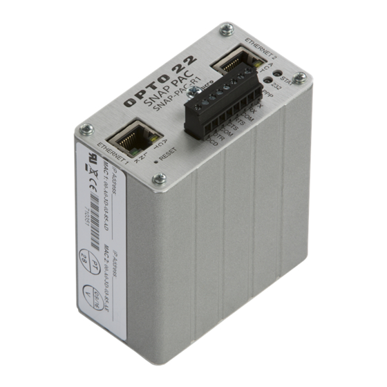
CHAPTER 3: SYSTEM INFORMATION Connectors and LEDs The following information applies to all SNAP PAC R-series controllers except Wired+Wireless models. For details on LED blink codes, see page Independent 10/100 Mbps Ethernet interfaces (RJ-45 connectors) RS-232 Port (Port 0) Description Ethernet LEDs MicroSD card slot... -
Page 42: Connectors And Leds-Wired+Wireless Models
SPECIFICATIONS, CONNECTORS, AND DIMENSIONS Connectors and LEDs—Wired+Wireless Models The following information applies to Wired+Wireless models (SNAP-PAC-R1-W and SNAP-PAC-R2-W). For details on LED blink codes, see page Independent 10/100 Mbps Wireless LAN antenna Ethernet interfaces (RJ-45 connectors) Ethernet LEDs MicroSD RS-232 Port (Port 0) -
Page 43: Dimensions
CHAPTER 3: SYSTEM INFORMATION Dimensions The basic dimensions are the same for all SNAP PAC R-series controllers. See the following page for antenna dimensions on Wired+Wireless models. SNAP PAC R-Series Controller User’s Guide... -
Page 44: Dimensions For Wired+Wireless Models
SPECIFICATIONS, CONNECTORS, AND DIMENSIONS Dimensions for Wired+Wireless Models This diagram applies to Wired+Wireless R-series PACs (SNAP-PAC-R1-W and SNAP-PAC-R2-W). SNAP PAC R-Series Controller User’s Guide... -
Page 45: Information On Features
CHAPTER 3: SYSTEM INFORMATION Information on Features All SNAP PAC R-series controllers offer many features, described in the following sections and summarized in the table on page Digital Point Features For information on configuring digital point features, see the PAC Control User’s Guide. (If you are not using PAC Control, see the PAC Manager User’s Guide. -
Page 46: Analog Point Features
INFORMATION ON FEATURES • On-pulse and off-pulse measurement—(R1 only) A pulse is a brief on (or off) state, usually repeated at a specific interval. The controller can measure the first pulse, that is, the amount of time the input stays on (or stays off). •... -
Page 47: Serial Communication
PAC Control strategy. To use PID loops, configure them in PAC Control or PAC Manager, and use PAC Control tuning tools for ease in debugging. See Opto 22 form #1700, the PAC Control User’s Guide, for more information. -
Page 48: Snap-Pac-R1 And -R2 Comparison Chart
SNAP-PAC-R1 AND -R2 COMPARISON CHART SNAP-PAC-R1 and -R2 Comparison Chart The following table compares SNAP PAC R-series controllers with firmware version 8.5. FEATURE Factory Mutual approval Digital I/O Input latching point features On/off status Watchdog timer High-speed counting (up to 20 kHz) - Page 49 CHAPTER 3: SYSTEM INFORMATION FEATURE Wired Ethernet network (two independent network interfaces) Security for wired network (IP filtering, port access) Wireless LAN interface (802.11a, b, or g) Security for wireless network (WPA2-AES, WPA-TKIP, WEP) OPC driver support Modbus/TCP (slave) EtherNet/IP for communication with Allen-Bradley RSLogix PLCs OptoMMP memory-mapped protocol SNMP (network management of I/O &...
- Page 50 SNAP-PAC-R1 AND -R2 COMPARISON CHART SNAP PAC R-Series Controller User’s Guide...
-
Page 51: Chapter 4: Maintenance And Troubleshooting
Chapter 4 4: Maintenance and Troubleshooting This chapter includes maintenance and troubleshooting information for SNAP PAC R-series controllers. In This Chapter Maintaining the SNAP PAC R-Series Controller Backup Battery..................46 Changing the Controller’s IP Address...........46 Loading New Firmware..............46 Setting Time and Date..............46 Resetting the Controller..............46 Using the MicroSD Card..............48 Blink Codes ..................63... -
Page 52: Maintaining The Snap Pac R-Series Controller
MAINTAINING THE SNAP PAC R-SERIES CONTROLLER Maintaining the SNAP PAC R-Series Controller Backup Battery The SNAP PAC R-series controller has a rechargeable battery that receives charging current whenever the controller has power. It will retain data for up to three years with the power off. NOTE: Models manufactured before July 1, 2007 have a user-replaceable 3-volt CR2032 Lithium battery (typical service life with power off: 5 years). - Page 53 Failsafe bootloader mode is a diagnostic mode that you don’t need to access unless you are troubleshooting a problem with Opto 22 Product Support. If your controller restarts in failsafe bootloader mode, simply cycle power to the device. This performs the simple reset described above and leaves the controller ready to load a new strategy.
-
Page 54: Using The Microsd Card
MAINTAINING THE SNAP PAC R-SERIES CONTROLLER Using the MicroSD Card SNAP PAC controllers manufactured in November 2008 and later have a microSD card slot in the top of the controller’s case. On a controller with a microSD card slot, the STAT LED blinks briefly about once every five seconds, indicating that the controller is checking to see if a card is in place. - Page 55 2010 have these versions. For older controllers, check versions in the PAC Manager Inspect window (see page 51). If you need a newer loader version, contact Opto 22 Product Support. 3 Behavior varies based on firmware and loader versions. See page 51 to check versions.
-
Page 56: Storing And Accessing Data Or Files
MAINTAINING THE SNAP PAC R-SERIES CONTROLLER Storing and Accessing Data or Files When inserted into the controller and accessed from a PC using FTP or PAC Control, the card appears as a directory in the controller’s file system named: Just like a PC might show a thumb sdcard0 drive as a directory named Removable Disk (E:), for example, the controller shows the card as a directory named sdcard0. -
Page 57: Displaying Free Space On The Card
CHAPTER 4: MAINTENANCE AND TROUBLESHOOTING You can also use the FTP communication handle in PAC Control to manipulate files. See the section “Moving Files via FTP,” also in Chapter 10 of the PAC Control User’s Guide. To move files to or from a PC, use any standard FTP software. (Don’t use PAC Manager as the FTP client, as it cannot see directories within the controller’s file system). -
Page 58: Replacing A Controller
New firmware versions are available from our website, www.opto22.com. See “Loading New Firmware” on page 46. For new loader versions, contact Opto 22 Product Support. Replacing a Controller A microSD card can be used to quickly commission a replacement controller in the unlikely event that an existing controller fails. - Page 59 CHAPTER 4: MAINTENANCE AND TROUBLESHOOTING b. In the Device Name field, type the name (or IP address) of the device. Click Status Write. c. In the Operation Command list, highlight Store configuration and IP settings to microSD. d. Click Send Command. The controller’s IP settings and all configuration data are saved to the card in a file located at /sdcard0/opto22/config/config.cfg.
- Page 60 MAINTAINING THE SNAP PAC R-SERIES CONTROLLER c. Choose one of the following: – If you’re using Secure Strategy Distribution (SSD), follow steps in form #1762, the PAC Terminal SSD Technical Note, to create a download file with the file extension .ssd. –...
-
Page 61: Updating Firmware
CHAPTER 4: MAINTENANCE AND TROUBLESHOOTING c. In the directory on the card, create a new directory and name it: sdcard0 strategy Copy the renamed strategy file (.cdf or .ssd) to the directory. sdcard0/strategy The card is now ready to be used as a commissioning card to replace the controller. Replacing the Failed Controller. - Page 62 MAINTAINING THE SNAP PAC R-SERIES CONTROLLER The original file extension does not have to be retained. To make sure the file is clearly identified, we recommend a name such as the following: where: PPP-TMM.mmb = controller type (R1, R2) = R for release (or B for beta) = major revision number = minor revision number = build letter...
-
Page 63: Booting From Firmware On The Card
CHAPTER 4: MAINTENANCE AND TROUBLESHOOTING The following sample command file updates firmware on the controller. Krn R2-R9.0a The following sample command file updates firmware on the controller and on two serial modules. The update commands for the serial modules must be listed first. This file updates version R2.0a on an RS-232 serial module in slot 3, firmware version R1.3c on a motion control module (a special type of serial module) in slot 6, and firmware version R9.0a on a SNAP-PAC-R2 controller. - Page 64 MAINTAINING THE SNAP PAC R-SERIES CONTROLLER NOTE: Wired controllers must have loader version 5.1b or newer. Wired+Wireless controllers must have loader version 6.0a or newer. Controllers configured for Secure Strategy Distribution (SSD) cannot boot from the card. 1. Locate the firmware file you wish to boot from and rename it to fit the 8 dot 3 filename format (see “Card Type and Format”...
-
Page 65: Updating, Running, Or Testing A Strategy
CHAPTER 4: MAINTENANCE AND TROUBLESHOOTING If the boot directory exists on the card, the STAT LED blinks green three times, quickly. Firmware is loaded. If the STAT LED blinks red, see “Blink Codes” in this chapter to determine the problem. If the STAT LED blinks green two times, either the boot directory is not present, the firmware file is invalid or does not match the controller, or the controller is an SSD controller. - Page 66 MAINTAINING THE SNAP PAC R-SERIES CONTROLLER 2. If your controller has a firmware version older than 9.0a and you want the strategy saved to flash memory, check the box Save strategy to flash memory after download. (This checkmark has no effect for firmware 9.0a and newer.) 3.
- Page 67 CHAPTER 4: MAINTENANCE AND TROUBLESHOOTING directory at the top level. The controller’s file system treats the card as a directory named sdcard0. 8. Copy the renamed strategy file to the directory on the microSD card. sdcard0/strategy Here’s an example of a strategy file in the strategy directory, looking at the card in the controller: Strategy file 9.
-
Page 68: Disabling Or Enabling Firmware And Strategy Updates Via The Card
MAINTAINING THE SNAP PAC R-SERIES CONTROLLER strategy was stopped, the new one will not run; you must start it manually. For firmware versions older than 9.0a, if you checked the Save to flash memory box, the strategy is saved to flash. For firmware 9.0a or newer, see step In either case, the STAT LED will blink steadily while the strategy is loading and then blink two sets of three blinks—green to indicate success, or red to indicate failure. -
Page 69: Blink Codes
CHAPTER 4: MAINTENANCE AND TROUBLESHOOTING Blink Codes “Connectors and LEDs” on page 35 for the location of LEDs. STAT LED The STAT LED on the top of a SNAP PAC R-series controller uses blink codes to indicate status conditions. The blink codes can be useful during operation and in troubleshooting. If the STAT LED is on and remains green, it indicates that a flowchart is running and a user task is being executed. -
Page 70: Ppp Led
MAINTAINING THE SNAP PAC R-SERIES CONTROLLER If the STAT LED is blinking red, it indicates the following: Number of Speed of Means Problem and Workaround Blinks Blinks Flash chips were not erased properly or programmed slow Flash programming failure properly. Contact Product Support. The firmware in the device is damaged. -
Page 71: 232 Led
Getting Device and Firmware Information If you need to contact Opto 22 Product Support for assistance in using an I/O unit or controller, it is helpful to have device and firmware information at hand before you call us. 1. Choose Start→Programs→Opto 22→PAC Project→PAC Manager. -
Page 72: Communicating With The Controller
TROUBLESHOOTING THE SNAP PAC R-SERIES CONTROLLER Keep this window open on your screen when you call Product Support. Communicating with the Controller If you attempt to connect to the controller using its IP address and you cannot, first check the following: •... -
Page 73: Pinging The Controller
Is the controller in reset mode? (Check for a blinking STAT LED. STAT blink codes are shown on page 63.) If you still cannot ping the controller, contact Opto 22 Product Support. (See page Accessing the Controller with PAC Manager Once you know you can ping the controller, try to access it using PAC Manager. - Page 74 TROUBLESHOOTING THE SNAP PAC R-SERIES CONTROLLER 2. In the PAC Manager main window, click the Inspect button 3. In the Device Name field, type the name (or IP address) of the controller (or choose it from the drop-down list). Press Enter or click Status Read. Information from the controller is displayed in the window: Date and time data...
-
Page 75: Solving Network Problems
If there are recurring problems in communicating with the controller, check your network. The wires, switches, and so on in your Ethernet network are not part of the Opto 22 hardware, but any problems in your network may affect communication with Opto 22 products. -
Page 76: Additional Troubleshooting Tools
If you are receiving frequent timeout messages from the I/O unit, you can change the TCP parameters in PAC Manager. 1. Choose Start > Programs > Opto 22 > PAC Project Software > PAC Manager. 2. In the PAC Manager main window, click the Inspect icon 3. - Page 77 CHAPTER 4: MAINTENANCE AND TROUBLESHOOTING CAUTION: Note the following recommended settings: TCP Minimum Retransmission Timeout (msec): TCP Initial Retransmission Timeout (msec): 3000 TCP Retransmission Attempts: TCP Idle Session Timeout (msec): 240,000 If you set these fields too low, you may not be able to communicate with the device at all, even through PAC Manager, to fix the settings.
-
Page 78: Troubleshooting I/O Modules: Frequently Asked Questions
Failures on the field side of all types of Opto 22 digital I/O modules occur extremely rarely and are typically the result of misapplication. The logic-side failures of Opto 22’s I/O modules are also extremely rare. - Page 79 A: Some solenoids and some types of halogen lights incorporate a diode in series with the coil or filament. This causes the light to behave as a half-wave rectifier. Opto 22 output modules have a built-in R-C snubber circuit in parallel with the output. The capacitor in this circuit charges up but cannot discharge through the series diode, causing a voltage to appear across the output terminals.
-
Page 80: Snap Analog Troubleshooting
The SNAP equipment is designed with a fail-safe voltage watchdog feature that inhibits operation when power supply voltage levels get too low, thus eliminating the possibility of unintentional output or input. Opto 22 offers DIN-rail-mountable power supplies for use with SNAP I/O systems. -
Page 81: Appendix: Snap Mounting Racks And Power Supplies
Appendix A Appendix: SNAP Mounting Racks and Power Supplies Introduction As shown in the illustration below, a SNAP PAC R-series I/O system has a SNAP PAC R-series controller, SNAP PAC rack, power supply, and modules. This appendix includes wiring diagram examples for assembling your SNAP PAC R-series controller, SNAP PAC rack, and power supply. -
Page 82: Snap Pac Mounting Racks
SNAP Power Supplies Primary Power Supply NOTE: For a more general discussion of using power supplies with Opto 22 systems, see Opto 22 form #1271, a technical note available on our website at www.opto22.com. SNAP PAC racks use a 5 VDC power source (5 VDC [-0.0, +0.1] at minimum 4.0 amps recommended). -
Page 83: Determining Power Requirements
APPENDIX: SNAP MOUNTING RACKS AND POWER SUPPLIES Determining Power Requirements Both the SNAP-PS5 and the SNAP-PS5-24DC power supplies provide 5 VDC power for loads up to 4 amps. The SNAP-PS5U provides 5 VDC for loads up to 5 amps. In most cases this power is sufficient for a SNAP processor, a rack, and the associated I/O modules. -
Page 84: Wiring The Primary Power Supply
SNAP POWER SUPPLIES Wiring the Primary Power Supply Use one power supply per I/O unit. Use 14 AWG wire. 1. Mount the SNAP-PS5 or SNAP-PS5-24DC power supply so that the attached red and black power wires will reach the + and – power terminals on the SNAP mounting rack. 2. - Page 85 APPENDIX: SNAP MOUNTING RACKS AND POWER SUPPLIES 1. Mount the SNAP-PS24 or SNAP-PS24U power supply in a location where the attached output power wires will reach the field connector for SNAP analog modules. The white and red wire is the positive wire (24 VDC). The white and black wire is the negative wire (24 VDC return).
- Page 86 SNAP POWER SUPPLIES SNAP PAC R-Series Controller User’s Guide...
-
Page 87: Index
Index Numerics serial, 3, 41 simultaneous, 18 232 LED, 65 wireless LAN, 2 with controller, 17 with enterprise systems, 24 computer, connecting directly to controller, 26 accessing controller over the Internet, 19 configuring analog input modules I/O points, 11 troubleshooting, 74 modem communication, 12 analog output modules PPP, 12... - Page 88 digital input modules help troubleshooting, 72 blink codes, 63 digital output modules LED descriptions, 35 troubleshooting, 72 network problems, 69 digital point features, 39 Product Support, 6 direct connection, 26 high-speed counters, 39 email, 24 I/O, 3 enterprise connectivity, 24 I/O modules enterprise management system, 24 installing, 8...
- Page 89 Scratch Pad areas, 23 sdcard0, 50 serial communication, 41 offset, 40 serial port, 35 OPC, 5, 24 SMTP, 24 Opto 22 Product Support, 6 SNMP, 24 OptoEnetSniff, 70 software, 3 output clamping, 40 installing, 7 specifications, 33 STAT LED, 63...
- Page 90 settings, 70 stack, 70 utilities technical support, 6 OptoEnetSniff, 70 third-party software, 24 timeout, 70 troubleshooting analog I/O modules, 74 watchdog, 39, 40 blink codes, 63 wireless LAN, 29 digital I/O modules, 72 communication, 2 LED descriptions, 35 network diagram, 30 network, 69 WLAN LED, 65 Product Support, 6...
Need help?
Do you have a question about the SNAP-PAC-R1 and is the answer not in the manual?
Questions and answers