Table of Contents
Advertisement
Quick Links
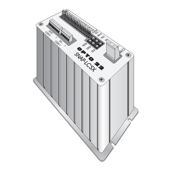
SNAP-LCSX AND LCSX-PLUS
INSTALLATION GUIDE
Form 1061-191112—November 2019
43044 Business Park Drive
Temecula
CA 92590-3614
•
•
Phone: 800-321-OPTO (6786) or 951-695-3000
Fax: 800-832-OPTO (6786) or 951-695-2712
www.opto22.com
Product Support Services
800-TEK-OPTO (835-6786) or 951-695-3080
Fax: 951-695-3017
Email: support@opto22.com
Web: support.opto22.com
Advertisement
Table of Contents
Troubleshooting


Need help?
Do you have a question about the LCSX-PLUS and is the answer not in the manual?
Questions and answers