
Related Manuals for OPTO 22 SNAP-PAC-R1


Summary of Contents for OPTO 22 SNAP-PAC-R1
- Page 1 Form 1595 SNAP PAC R-SERIES CONTROLLER USER’S GUIDE SNAP-PAC-R1 SNAP-PAC-R2 SNAP-PAC-R1-FM SNAP-PAC-R2-FM SNAP-PAC-R1-W SNAP-PAC-R2-W...
- Page 3 SNAP PAC R-SERIES CONTROLLER USER’S GUIDE SNAP-PAC-R1 SNAP-PAC-R2 SNAP-PAC-R1-FM SNAP-PAC-R2-FM SNAP-PAC-R1-W SNAP-PAC-R2-W Form 1595-131202—December 2013 43044 Business Park Drive Temecula CA 92590-3614 • • Phone: 800-321-OPTO (6786) or 951-695-3000 Fax: 800-832-OPTO (6786) or 951-695-2712 www.opto22.com Product Support Services 800-TEK-OPTO (835-6786) or 951-695-3080 Fax: 951-695-3017 Email: support@opto22.com...
- Page 4 Specifications are subject to change without notice. Opto 22 warrants all of its products to be free from defects in material or workmanship for 30 months from the manufacturing date code. This warranty is limited to the original cost of the unit only and does not cover installation, labor, or any other contingent costs.
-
Page 5: Table Of Contents
Table of Contents Chapter 1: Overview ............1 Introduction . - Page 6 SNAP-PAC-R1 and -R2 Comparison Chart ........
- Page 7 Booting from Firmware on the Card ..........61 Updating, Running, or Testing a Strategy .
- Page 8 SNAP PAC R-Series Controller User’s Guide...
-
Page 9: Chapter 1: Overview
Six models of the SNAP PAC R-series controller are available: • SNAP-PAC-R1, SNAP-PAC-R1-FM, and SNAP-PAC-R1-W each control a mix of SNAP analog, digital (both standard and high-density), and serial modules. Full digital functions include high-speed counting, quadrature counting, pulse measurement, and period and frequency measurement. -
Page 10: Ethernet Communication
The -FM model is Factory Mutual approved. The -W model adds wireless LAN capability (see page 2 for more information). Built-in functions and comparisons of the SNAP-PAC-R1 and SNAP-PAC-R2 are shown in the table on page Ethernet Communication All SNAP PAC R-series controllers communicate over standard 10/100 Mbps Ethernet networks and can be attached to an existing network. -
Page 11: Serial Communication
SNAP serial communication modules on the rack. NOTE: The R-series controller does not include an RS-485 port and cannot be used to control Opto 22 serial I/O processors, such as the SNAP PAC SB-series brains. Use an S-series controller for serial brains. -
Page 12: Software Availability
Ethernet-based controllers and I/O. Using OptoOPCServer, you can consolidate data from all these Opto 22 systems into the OPC client software of your choice, such as third-party HMI and data acquisition packages, and custom software applications you create with tools such ®... -
Page 13: About This Guide
EtherNet/IP. See the EtherNet/IP for SNAP PAC Protocol Guide, form #1770. The following sections are included in this user’s guide: Chapter 1: Overview—information about the guide and how to reach Opto 22 Product Support. Chapter 2: Installation—quick-start steps to get SNAP PAC R-series controllers up and running quickly. -
Page 14: For Help
For Help If you have problems installing or using SNAP PAC R-series controllers and cannot find the help you need in this guide or on our website, contact Opto 22 Product Support. Phone: 800-TEK-OPTO (800-835-6786) -
Page 15: Chapter 2: Installation
Chapter 2 2: Installation If you already know how you will use the SNAP PAC R-series controller and want to get it running quickly, follow the sections in this chapter. To learn about communication options and networking, start on page 17. -
Page 16: Installing Hardware
INSTALLING HARDWARE NOTE: If you run PAC Project applications in Microsoft Windows XP, make sure you have Service Pack 3 installed. Otherwise, a Microsoft bug may cause the system to crash. See OptoKB article #KB49838 for details. Installing Hardware Assemble the rack and power supply according to the directions that came with them. For help with wiring, see the product data sheets, which are available on our website at www.opto22.com. -
Page 17: Removing A Module
CHAPTER 2: INSTALLATION 3. With the module correctly aligned Module keys over the connector, push on the module to snap it into place. When positioning modules next to each other, be sure to align the male and female module keys (shown in the detailed view in the illustration at right) before snapping a module into position. -
Page 18: Installing The Controller
79) for information on power supplies and wiring. 8. Before turning on power to the rack, follow instructions in Opto 22 form #1704, the PAC Manager User’ s Guide, to assign an IP address to the controller (required for both standard and wired+wireless models). -
Page 19: What's Next
To communicate with an Allen-Bradley Logix PLC or other system using EtherNet/IP, see the EtherNet/IP for SNAP PAC Protocol Guide, form #1770. To program your own applications, see Opto 22 form #1465, the OptoMMP Protocol Guide. Configuring I/O No matter how you communicate with SNAP PAC R-series controllers, you will need to configure I/O points and controller features. -
Page 20: Using Ppp Over A Modem
USING PPP OVER A MODEM features that are not available in PAC Control. However, you cannot use the loopback address in PAC Manager. Choose your configuration tool based on what you need to do: Use PAC Control for I/O configuration if… Use PAC Manager for I/O configuration if…... -
Page 21: Configuring Ppp On The Controller
14) on the PC. Configuring PPP on the Controller To configure PPP on the SNAP PAC R-series controller, see instructions in Opto 22 form #1704, the PAC Manager User’ s Guide. Also use this guide to assign an IP address to the Ethernet ports, configure points, and store configuration to flash. -
Page 22: Configuring Microsoft Windows Dial-Up Networking On Windows Xp
USING PPP OVER A MODEM NOTE: Configuration settings must be stored to the modem’ s NVRAM so they will be loaded when the SNAP PAC R-series controller sends a reset command to the modem. 3. If PCs will dial up the controller, set up Windows dial-up networking on the PCs that will call the controller. - Page 23 CHAPTER 2: INSTALLATION Options Tab Security Tab SNAP PAC R-Series Controller User’s Guide...
- Page 24 USING PPP OVER A MODEM Networking Tab Advanced Tab SNAP PAC R-Series Controller User’s Guide...
-
Page 25: Chapter 3: System Information
................Specifications, Connectors, and Dimensions .... Information on Features............. SNAP-PAC-R1 and -R2 Comparison Chart ....Communication Options SNAP PAC R-series controllers communicate using TCP/IP or UDP/IP over a wired or wireless network. Physical Layer—All SNAP PAC R-series controllers communicate over a 10- or 100-Mbps wired Ethernet link. -
Page 26: Simultaneous Communication
COMMUNICATION OPTIONS • Custom software applications are easy to develop using our OptoMMP Communication Toolkit with ActiveX components and C++ classes. They use an IEEE 1394-based protocol to read and write to SNAP PAC R-series controllers. For developers not using Microsoft Windows, our IEEE 1394-based protocol is open and documented. •... -
Page 27: Accessing Snap R-Series Controllers Over The Internet
IEEE 1394-based For Communication Toolkit or IEEE 1394-based protocol, enterprise management system. protocol see OptoMMP Protocol Guide. Give technicians an Opto 22 PAC Display See PAC Display User’s Guide. HMI with alarming and trending. Monitor and control SNAP PAC PAC Control... -
Page 28: System Architecture
Share strategy variable data PAC Control Memory map PAC Control does not write directly to peers, but places with Opto 22 controllers and (writes to memory Scratch Pad areas data in the memory map so peers can retrieve it by read-... -
Page 29: The I/O Side Of The Controller
If you do need to refer to it, however, the complete list of memory map addresses is in Opto 22 form 1465, the OptoMMP Protocol Guide. - Page 30 SYSTEM ARCHITECTURE controller runs it independently. (For information on using PAC Control, see form #1700, the PAC Control User’ s Guide, and form #1701, the PAC Control Command Reference.) You use PAC Control on a PC connected to the network, so you can create your control strategy and download it to the controller.
-
Page 31: Using Data For Peer-To-Peer Communication
CHAPTER 3: SYSTEM INFORMATION Using Data for Peer-to-Peer Communication What if you have multiple SNAP PAC controllers? What if each one is running a different PAC Control strategy, and they need to share variable data? Or what if you need to share data between a SNAP PAC System and an Allen-Bradley Logix-based PLC? Scratch Pad areas within the SNAP PAC R-series controller’s memory map provide a way for other devices on the Ethernet network to access data in the controller. -
Page 32: Communicating With Enterprise Systems And Third-Party Software
SYSTEM ARCHITECTURE For more information on using PAC Control commands for peer-to-peer communication, see “Communication Commands” in Chapter 10 of the PAC Control User’s Guide and individual commands in the PAC Control Command Reference. If you are not using PAC Control but writing your own software applications to access the Scratch Pad areas, see the OptoMMP Protocol Guide. -
Page 33: The Complete System
CHAPTER 3: SYSTEM INFORMATION All of the protocols shown in the diagram, except FTP, can be used to communicate with both the fixed memory map area and the Scratch Pad area, so you can access both I/O point data in the fixed area and strategy variable data placed in the Scratch Pad area. In addition, strategy variable data from the PAC Control database can be directly used by OPC clients. - Page 34 SYSTEM ARCHITECTURE SNAP PAC R-Series Controller User’s Guide...
-
Page 35: Networking
CHAPTER 3: SYSTEM INFORMATION Networking From a physical standpoint, SNAP PAC R-series controllers can be networked in several ways: • Connected directly to a PC or controller using a crossover cable • Attached to an existing TCP/IP Ethernet network • As part of an independent network built with standard Ethernet hardware •... -
Page 36: Attaching The Controller To An Existing Ethernet Network
NETWORKING NOTE: Make sure you put 3 and 6 on the same pair, or you may experience noise and distance limitations. Also, make sure to include all pairs, since they are required for 100 Mbps. Attaching the Controller to an Existing Ethernet Network The first rule in attaching SNAP PAC R-series controllers to an existing network is to work closely with your system administrator, who must determine network topology and hardware. -
Page 37: Segmenting The Control Network
CHAPTER 3: SYSTEM INFORMATION Segmenting the Control Network If you need to segment the control system network from the main network backbone, you can use the two Ethernet interfaces on either the SNAP PAC R-series or an S-series controller. One interface can be connected to the enterprise network, and the other used for the control system. -
Page 38: Using The Controller In A Wireless Lan
Modem” on page Using the Controller in a Wireless LAN A Wired+Wireless PAC-R (SNAP-PAC-R1-W or SNAP-PAC-R2-W) can also be used in a wireless local area network (LAN) built with components that meet 802.11a, b, or g standards, depending on which works best for your environment. Both ad-hoc and infrastructure modes are supported. -
Page 39: Network Architecture Diagrams
CHAPTER 3: SYSTEM INFORMATION Network Architecture Diagrams Because SNAP PAC R-series controllers have two Ethernet interfaces and an RS-232 serial interface—and Wired+WIreless PACs add a wireless LAN interface—these controllers are suitable for use in a variety of system layouts and architectures. For example, the independent Ethernet interfaces let you configure a network for link redundancy or segmented networking. -
Page 40: Network Segmenting: Wired And Wireless Networks
The network shown in this diagram requires a Wired+Wireless R-series controller (SNAP-PAC-R1-W or SNAP-PAC-R2-W). The PAC runs a PAC Control strategy and controls one or more remote I/O units via a wireless access point. The controller is also connected to a separate, wired enterprise network through one of its wired Ethernet network interfaces. -
Page 41: Network Segmenting: Ethernet Connections To Host And I/O Units
CHAPTER 3: SYSTEM INFORMATION Network Segmenting: Ethernet Connections to Host and I/O Units The following diagram shows two Opto 22 I/O units connected together over an Ethernet network and controlled by a SNAP PAC R-series controller running a PAC Control strategy. -
Page 42: Ethernet Link Redundancy
NOTE: If you need controller redundancy (two controllers running concurrently, with one able to take over if the other fails), use SNAP PAC S-series standalone controllers with the PAC Redundancy Option Kit and PAC Control Professional. For more information, see the Opto 22 website. -
Page 43: Specifications, Connectors, And Dimensions
CHAPTER 3: SYSTEM INFORMATION Specifications, Connectors, and Dimensions Specifications The following table shows specifications for SNAP-PAC-R1 and -R2 controllers. The table continues on the next page. Processor ® 200 MHz 32-bit ColdFire 5475 with integrated floating-point unit (FPU) Memory Total RAM Wired+Wireless models 32 MB;... - Page 44 5 years). Connecting to a serial device requires configuration in PAC Manager; PAC Control handles communication. Requires a Wired+Wireless model (SNAP-PAC-R1-W or SNAP-PAC-R2-W). SNAP-PAC-R1s with serial numbers lower than 600,000 are limited to eight 4-channel digital modules per rack; remaining eight can be analog, serial, and high-density digital modules.
-
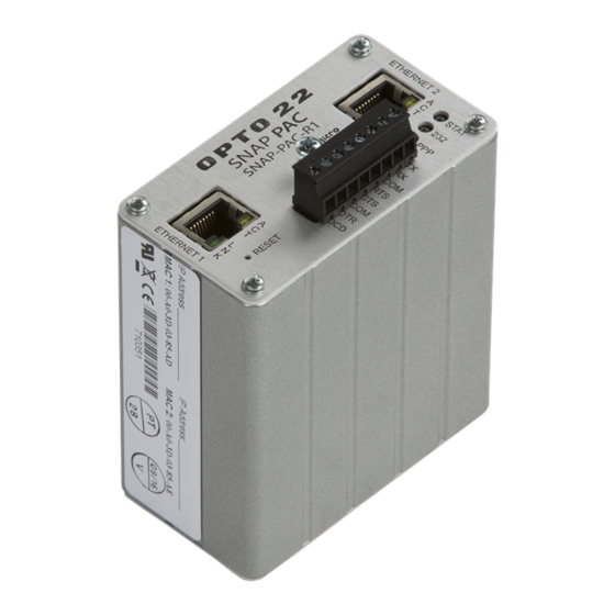
Page 45: Connectors And Leds
CHAPTER 3: SYSTEM INFORMATION Connectors and LEDs The following information applies to all SNAP PAC R-series controllers except Wired+Wireless models. For details on LED blink codes, see page Independent 10/100 Mbps Ethernet interfaces (RJ-45 connectors) RS-232 Port (Port 0) Ethernet Description LEDs MicroSD... -
Page 46: Connectors And Leds-Wired+Wireless Models
SPECIFICATIONS, CONNECTORS, AND DIMENSIONS Connectors and LEDs—Wired+Wireless Models The following information applies to Wired+Wireless models (SNAP-PAC-R1-W and SNAP-PAC-R2-W). For details on LED blink codes, see page Independent 10/100 Mbps Wireless LAN antenna Ethernet interfaces (RJ-45 connectors) Ethernet MicroSD card RS-232 Port (Port 0) -
Page 47: Dimensions
CHAPTER 3: SYSTEM INFORMATION Dimensions The basic dimensions are the same for all SNAP PAC R-series controllers. See the following page for antenna dimensions on Wired+Wireless models. SNAP PAC R-Series Controller User’s Guide... -
Page 48: Dimensions For Wired+Wireless Models
SPECIFICATIONS, CONNECTORS, AND DIMENSIONS Dimensions for Wired+Wireless Models This diagram applies to Wired+Wireless R-series PACs (SNAP-PAC-R1-W and SNAP-PAC-R2-W). SNAP PAC R-Series Controller User’s Guide... -
Page 49: Information On Features
CHAPTER 3: SYSTEM INFORMATION Information on Features All SNAP PAC R-series controllers offer many features, described in the following sections and summarized in the table on page Digital Point Features To configure digital point features, see the PAC Control User’ s Guide. (Or PAC Manager User’s Guide, if you are not using PAC Control. -
Page 50: Analog Point Features
INFORMATION ON FEATURES • Frequency Measurement—(R1 only) Frequency is the speed with which a digital point changes state. It’s usually measured in counts per second. For example, reading the frequency can help you determine the speed of rotating machinery. • Period Measurement—(R1 only) Period refers to the elapsed time for a complete on-off-on transition on a digital point. -
Page 51: Serial Communication
PAC Control strategy. To use PID loops, configure them in PAC Control or PAC Manager, and use PAC Control tuning tools for ease in debugging. See Opto 22 form #1700, the PAC Control User’s Guide, for more information. -
Page 52: Snap-Pac-R1 And -R2 Comparison Chart
SNAP-PAC-R1 AND -R2 COMPARISON CHART SNAP-PAC-R1 and -R2 Comparison Chart The following table compares SNAP PAC R-series controllers with firmware 8.5 or newer. FEATURE Factory Mutual approval Digital I/O Input latching point features On/off status Watchdog timer High-speed counting (up to 20 kHz) - Page 53 CHAPTER 3: SYSTEM INFORMATION FEATURE Wired Ethernet network (two independent network interfaces) Security for wired network (IP filtering, port access) Wireless LAN interface (802.11a, b, or g) Security for wireless network (WPA2-AES, WPA-TKIP, WEP) OPC driver support Modbus/TCP (slave) EtherNet/IP for communication with Allen-Bradley RSLogix PLCs OptoMMP memory-mapped protocol SNMP (network management of I/O &...
- Page 54 SNAP-PAC-R1 AND -R2 COMPARISON CHART SNAP PAC R-Series Controller User’s Guide...
-
Page 55: Chapter 4: Maintenance And Troubleshooting
Chapter 4 4: Maintenance and Troubleshooting This chapter includes maintenance and troubleshooting information for SNAP PAC R-series controllers. In This Chapter Maintaining the SNAP PAC R-Series Controller Backup Battery....................Changing the Controller’s IP Address ..........Loading New Firmware................Setting Time and Date ................ -
Page 56: Maintaining The Snap Pac R-Series Controller
MAINTAINING THE SNAP PAC R-SERIES CONTROLLER Maintaining the SNAP PAC R-Series Controller Backup Battery The SNAP PAC R-series controller has a rechargeable battery that receives charging current whenever the controller has power. It will retain data for up to three years with the power off. -
Page 57: Resetting The Controller
2. Depending on the type of reset you need, press and hold down the RESET button as described below. DO NOT hold the button down too long. NOTE: Do not reset the brain to hardware test mode unless Opto 22 Product Support tells you to. Reset type... -
Page 58: Using The Microsd Card
To determine firmware version, see page Opto 22 Product Support recommends that you update controller firmware to the latest version if you are going to use a microSD card. Later firmware versions have added significant functionality and fixed problems. To download the latest firmware, go to www.opto22.com/site/downloads... - Page 59 CHAPTER 4: MAINTENANCE AND TROUBLESHOOTING • To update firmware on the controller or on a serial communication module on the controller’s rack. The card provides a convenient way to update firmware on non-networked controllers. It’s also useful if PAC Manager is not available to update firmware.
-
Page 60: Storing And Accessing Data Or Files
MAINTAINING THE SNAP PAC R-SERIES CONTROLLER To do this When Put card in... Use this method See pg PC with card Create command file; copy it and the firmware In advance reader file to card. Update non-net- Insert card into controller. worked controller Controller runs firmware from card until reset. -
Page 61: Displaying Free Space On The Card
CHAPTER 4: MAINTENANCE AND TROUBLESHOOTING microSD card Files in PAC’s file system Within the directory on the controller (or the root if the card is in a card reader), sdcard0 you can create other directories and create or add files, up to a maximum of 512 files and directories. -
Page 62: Checking Firmware And Loader Versions
MAINTAINING THE SNAP PAC R-SERIES CONTROLLER In a PAC Control strategy, for example, you could notify an operator if the card needs replacing, based on the number of bytes still unused. 1. Make sure the card is in the controller. 2. -
Page 63: Replacing A Controller
“Loading New Firmware” on page 48 “Loading New Firmware” on page 49. For new loader versions, contact Opto 22 Product Support. Replacing a Controller A microSD card can be used to quickly commission a replacement controller in the unlikely event that an existing controller fails. The card rapidly configures the replacement with the original controller’s IP address, firmware, configuration, and strategy. - Page 64 MAINTAINING THE SNAP PAC R-SERIES CONTROLLER c. In the Operation Command list, highlight Store configuration and IP settings to microSD. d. Click Send Command. The controller’s IP settings and all configuration data are saved to the card in a file located at /sdcard0/opto22/config/config.cfg.
- Page 65 CHAPTER 4: MAINTENANCE AND TROUBLESHOOTING – If you’re using Secure Strategy Distribution (SSD), follow steps in form #1762, the PAC Terminal SSD Technical Note, to create a download file with the file extension .ssd. – Otherwise, compile the strategy as a Control Engine Download file (.cdf ) by right-clicking the name of the control engine in the Strategy Tree and choosing Compile Control Engine Download File from the pop-up menu.
-
Page 66: Updating Firmware
MAINTAINING THE SNAP PAC R-SERIES CONTROLLER c. In the directory on the card, create a new directory and name it: sdcard0 strategy Copy the renamed strategy file (.cdf or .ssd) to the directory. sdcard0/strategy The card is now ready to be used as a commissioning card to replace the controller. Replacing the Failed Controller. - Page 67 CHAPTER 4: MAINTENANCE AND TROUBLESHOOTING firmware. If you want only the firmware saved, delete configuration and strategy files from the card. CAUTION: Updating firmware deletes your PAC Control strategy (even if stored to flash memory) and your persistent variables. Make sure you have archived your strategy before loading new firmware.
- Page 68 MAINTAINING THE SNAP PAC R-SERIES CONTROLLER 5. In the file, include the following commands as needed, all in the same file. command All commands are CASE SENSITIVE. To do this Use command Details <file> is the firmware path and file as the microSD card sees it, so do not include sdcard0 directory in the path.
-
Page 69: Booting From Firmware On The Card
CHAPTER 4: MAINTENANCE AND TROUBLESHOOTING CAUTION: Make sure you know what is on the card before updating firmware! Any IP address, configuration, or strategy data that exists on the card will also be saved to flash memory along with the firmware. 7. -
Page 70: Updating, Running, Or Testing A Strategy
MAINTAINING THE SNAP PAC R-SERIES CONTROLLER IMPORTANT: The boot directory must contain only one firmware file. If it contains more than one, the wrong firmware may be loaded. 4. If the card contains a command file or any other firmware files, delete them. 5. - Page 71 CHAPTER 4: MAINTENANCE AND TROUBLESHOOTING strategy. If you want only the strategy saved, delete configuration and firmware files from the card. 1. In PAC Control Configure mode, choose File→Strategy Options. Click the Download tab. 2. If you want to set the strategy to autorun, check the box Set autorun flag after download.
- Page 72 MAINTAINING THE SNAP PAC R-SERIES CONTROLLER Remember, if you are looking at the card in the controller, you create the strategy directory in the directory. If you are looking at the card in a card reader, create sdcard0 directory at the top level. The controller’s file system treats the card as a strategy directory named sdcard0.
-
Page 73: Disabling Or Enabling Firmware And Strategy Updates Via The Card
CHAPTER 4: MAINTENANCE AND TROUBLESHOOTING The STAT LED blinks steadily while the strategy is loading and then blinks two sets of three blinks—green to indicate success, or red to indicate failure. When the STAT LED no longer blinks steadily, but blinks only once every five seconds, it has finished. 10. - Page 74 MAINTAINING THE SNAP PAC R-SERIES CONTROLLER NOTE: If your R-series PAC has a microSD card slot, the STAT LED will briefly blink once every five seconds as it reads the card (or checks to see whether a card is present). For example, if the STAT LED is solid green or solid orange, it will still blink briefly every five seconds.
-
Page 75: Ppp Led
CHAPTER 4: MAINTENANCE AND TROUBLESHOOTING Number of Speed of Means Problem and Workaround Blinks Blinks Firmware or hardware problem. Confirm Ethernet cables are connected. Try turning off power to the slow Loader problem controller and turning it back on again. Call Product Support if the error is repeated. -
Page 76: Wlan Led
Help” on page Getting Device and Firmware Information If you need to contact Opto 22 Product Support for assistance in using an I/O unit or controller, it is helpful to have device and firmware information at hand before you call us. -
Page 77: Communicating With The Controller
CHAPTER 4: MAINTENANCE AND TROUBLESHOOTING Keep this window open on your screen when you call Product Support. Communicating with the Controller If you attempt to connect to the controller using its IP address and you cannot, first check the following: •... -
Page 78: Pinging The Controller
Once you know you can ping the controller, try to access it using PAC Manager. You will need to know the controller’s IP address. 1. If PAC Manager is not already open, choose Start > Programs > Opto 22 > PAC Project > PAC Manager. - Page 79 CHAPTER 4: MAINTENANCE AND TROUBLESHOOTING 2. In the PAC Manager main window, click the Inspect button 3. In the Device Name field, type the name (or IP address) of the controller (or choose it from the drop-down list). Press Enter or click Status Read. Information from the controller is displayed in the window: Date and time data...
-
Page 80: Solving Network Problems
If there are recurring problems in communicating with the controller, check your network. The wires, switches, and so on in your Ethernet network are not part of the Opto 22 hardware, but any problems in your network may affect communication with Opto 22 products. -
Page 81: Additional Troubleshooting Tools
If you are receiving frequent timeout messages from the I/O unit, you can change the TCP parameters in PAC Manager. 1. Choose Start > Programs > Opto 22 > PAC Project Software > PAC Manager. 2. In the PAC Manager main window, click the Inspect icon 3. - Page 82 TROUBLESHOOTING THE SNAP PAC R-SERIES CONTROLLER CAUTION: Note the following recommended settings: TCP Minimum Retransmission Timeout (msec): 250 TCP Initial Retransmission Timeout (msec): 3000 TCP Retransmission Attempts: TCP Idle Session Timeout (msec): 240,000 If you set these fields too low, you may not be able to communicate with the device at all, even through PAC Manager, to fix the settings.
-
Page 83: Troubleshooting I/O Modules: Frequently Asked Questions
A: Loss of function in a SNAP digital module is normally caused by misapplication. As with Opto 22’s other digital I/O module families, there is no one way in which SNAP I/O modules fail. Output modules normally fail in a different way than inputs. - Page 84 A: Some solenoids and some types of halogen lights incorporate a diode in series with the coil or filament. This causes the light to behave as a half-wave rectifier. Opto 22 output modules have a built-in R-C snubber circuit in parallel with the output. The capacitor in this circuit charges up but cannot discharge through the series diode, causing a voltage to appear across the output terminals.
-
Page 85: Snap Analog Troubleshooting
The SNAP equipment is designed with a fail-safe voltage watchdog feature that inhibits operation when power supply voltage levels get too low, thus eliminating the possibility of unintentional output or input. Opto 22 offers DIN-rail-mountable power supplies for use with SNAP I/O systems. - Page 86 TROUBLESHOOTING I/O MODULES: FREQUENTLY ASKED QUESTIONS loop through the module. A ground loop through the module could result in almost anything, from inaccurate readings to catastrophic failure of the module. SNAP analog modules, like any high-level electronics, require protection from electrical noise in high-noise environments, such as installations near arc or plasma equipment or AC inverters.
-
Page 87: Appendix: Snap Mounting Racks And Power Supplies
Appendix A Appendix: SNAP Mounting Racks and Power Supplies Introduction As shown in the illustration below, a SNAP PAC R-series I/O system has a SNAP PAC R-series controller, SNAP PAC rack, power supply, and modules. This appendix includes wiring diagram examples for assembling your SNAP PAC R-series controller, SNAP PAC rack, and power supply. -
Page 88: Snap Power Supplies
SNAP Power Supplies Primary Power Supply NOTE: For a more general discussion of using power supplies with Opto 22 systems, see Opto 22 form #1271, a technical note available on our website at www.opto22.com. SNAP PAC racks use a 5 VDC power source (5 VDC [-0.0, +0.1] at minimum 4.0 amps recommended). - Page 89 APPENDIX: SNAP MOUNTING RACKS AND POWER SUPPLIES modules, especially special-purpose modules, may require additional power. You can use the following table to help determine power needs for your I/O units. X Power Total Power Item Quantity Req. (Amps) Required (Amps) SNAP PAC R-series controller (except wired+wireless) 1.200 1.200 or...
-
Page 90: Wiring The Primary Power Supply
SNAP POWER SUPPLIES Wiring the Primary Power Supply Use one power supply per I/O unit. Use 14 AWG wire. 1. Mount the SNAP-PS5 or SNAP-PS5-24DC power supply so that the attached red and black power wires will reach the + and – power terminals on the SNAP mounting rack. 2. - Page 91 APPENDIX: SNAP MOUNTING RACKS AND POWER SUPPLIES The white and red wire is the positive wire (24 VDC). The white and black wire is the negative wire (24 VDC return). 2. If you are wiring directly to the module, see the wiring diagram for the specific module you are using.
- Page 92 SNAP POWER SUPPLIES SNAP PAC R-Series Controller User’s Guide...
-
Page 93: Index
Index , 17 Numerics with controller , 24 with enterprise systems , 67 232 LED , 27 computer, connecting directly to controller configuring , 11 I/O points , 12 modem communication , 19 accessing controller over the Internet , 12 analog input modules connecting , 77... - Page 94 , 41 features installing , 24 email controller (quick start) , 24 enterprise connectivity , 10 controller on rack , 24 enterprise management system I/O modules error codes , 13 modem , 65 blink codes mounting rack , 37 Ethernet interface , 80 power supplies Ethernet network...
- Page 95 , 24 SMTP , 24 SNMP , 42 offset software , 5, 24 installing Opto 22 Product Support , 35 specifications , 73 OptoEnetSniff , 65 STAT LED , 42 output clamping , 65 status conditions (blink codes)
- Page 96 SNAP PAC R-Series Controller User’s Guide...
Need help?
Do you have a question about the SNAP-PAC-R1 and is the answer not in the manual?
Questions and answers