Advertisement
Quick Links
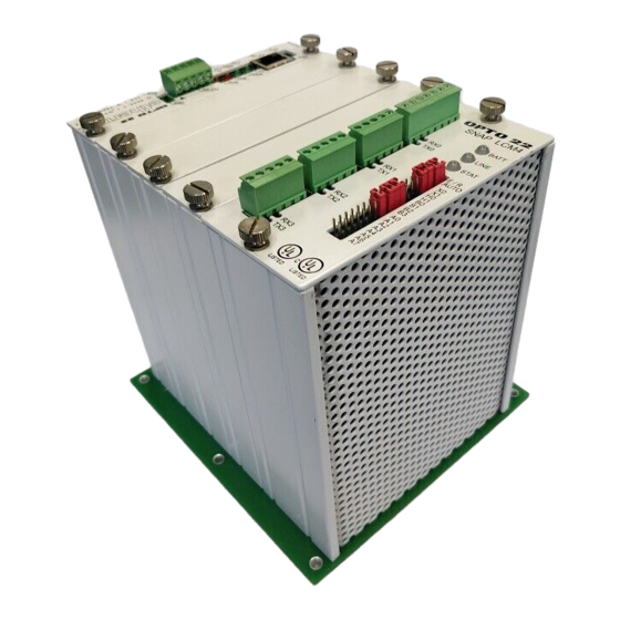
SNAP-LCM4
USER'S GUIDE
Form 1122-191204—December 2019
43044 Business Park Drive
Temecula
CA 92590-3614
•
•
Phone: 800-321-OPTO (6786) or 951-695-3000
Fax: 800-832-OPTO (6786) or 951-695-2712
www.opto22.com
Product Support Services
800-TEK-OPTO (835-6786) or 951-695-3080
Fax: 951-695-3017
Email: support@opto22.com
Web: support.opto22.com
SNAP-LCM4 User's Guide
i
Advertisement

Subscribe to Our Youtube Channel
Related Manuals for OPTO 22 SNAP-LCM4


Summary of Contents for OPTO 22 SNAP-LCM4
- Page 1 USER’S GUIDE Form 1122-191204—December 2019 43044 Business Park Drive Temecula CA 92590-3614 • • Phone: 800-321-OPTO (6786) or 951-695-3000 Fax: 800-832-OPTO (6786) or 951-695-2712 www.opto22.com Product Support Services 800-TEK-OPTO (835-6786) or 951-695-3080 Fax: 951-695-3017 Email: support@opto22.com Web: support.opto22.com SNAP-LCM4 User’s Guide...
- Page 2 Specifications are subject to change without notice. Opto 22 warrants all of its products to be free from defects in material or workmanship for 30 months from the manufacturing date code. This warranty is limited to the original cost of the unit only and does not cover installation, labor, or any other contingent costs.
- Page 3 COM0 RS-485 Configuration and Wiring ..........16 SNAP-LCM4 User’s Guide...
- Page 4 Third-Party Power Supply Vendors ............30 SNAP-LCM4 User’s Guide...
- Page 5 The SNAP-LCM4 is a powerful industrial controller that provides real-time control and communication to input/output (I/O) systems, serial devices, motion controllers, and networks. The SNAP-LCM4 controller is designed for use with Opto 22’s SNAP or Mistic remote I/O systems and Opto 22 ®...
- Page 6 SNAP-LCM4. FOR HELP If you have problems installing or using the SNAP-LCM4 controller and cannot find the help you need in this guide, contact Opto 22 Product Support.
- Page 7 The SNAP-LCM4 is designed for easy configuration in a variety of communication scenarios, including Ethernet, serial, ARCNET, and remote connections. It can be integrated with Opto 22’s digital and analog I/O systems as well as with other intelligent equipment devices, such as industrial PCs, M4RTUs, or other Opto 22 controllers.
- Page 8 1: INTRODUCTION ARCNET Network Remote Communication SNAP-LCM4 User’s Guide...
- Page 9 SNAP-LCM4 DESCRIPTION Using these communication options, the LCM4 can connect to a variety of Opto 22 I/O, as the following diagram demonstrates: LCM4 I/O Connection Options SNAP-LCM4 User’s Guide...
- Page 10 ™ • OptoControl , a graphical, flowchart-based development environment for machine control and process applications, which can run on a real-time industrial controller such as the SNAP-LCM4 or in a pure ® ® Microsoft Windows NT environment ™...
- Page 11 Chapter 2 2: Quick Start This section gives quick instructions for installing a generic SNAP-LCM4 controller using factory-default settings, which are shown on page 11. If you are not using the factory defaults, see the detailed instructions in the following sections.
- Page 12 With the power supply off or unplugged, connect it to the controller. The SNAP-LCM4 controller requires only 5 VDC power, which can be supplied by the Opto 22 SNAP-PS5 or any 5 V power supply meeting SNAP-LCM4 power requirements.
- Page 13 Cut off the end of the cable that DOES NOT plug into the computer and wire the cable as shown in the diagram on the following page. Important: If RTS and CTS are not used, be sure to connect RTS to CTS on the SNAP-LCM4 as shown below.
- Page 14 2: QUICK START Configure the controller using OptoControl. – In order to be useful with a SNAP-LCM4 controller, a PC must have at least one element of Opto 22’s FactoryFloor software suite installed: OptoControl, OptoDisplay, OptoServer, or OptoTerm. – This guide assumes that you will configure the controller using OptoControl. For instructions, see the OptoControl User’s Guide (Opto 22 Form number 724).
- Page 15 Pin 1 1200 Bd 600 Bd Out Out 300 Bd Bit 0 In Bit 1 In Bit 2 In Address 0– Bit 3 In Address Bits Bit 4 In Bit 5 In Bit 6 In Bit 7 In SNAP-LCM4 User’s Guide...
- Page 16 The controller host port jumpers H0 and H1 determine which port the controller’s default host task will be started on. Because the host task is required for communication to any of Opto 22’s programming or interface software, the default host port must be set to the port attached to the host computer. The factory setting is COM0.
- Page 17 There is no operational difference between execution from battery-backed RAM or ROM, except that the SNAP-LCM4 has significantly more space available in RAM for program storage. The drawback to execution from RAM is that the program is lost when the backup battery dies. (Battery life typically exceeds three years.) Before the controller will execute a program from ROM, you must have stored the program in Flash ROM by selecting that download function in OptoControl.
- Page 18 = Disabled If you need to change these defaults, use the OptoControl command Configure Port. See the OptoControl Command Reference (Opto 22 form #725) for details on using the command. Removing the Serial Card Remove the faceplate thumbscrews and the faceplate. Carefully pull straight up on the serial card (the one with the port connectors) to remove it.
- Page 19 JP3 control COM0; the jumpers shown grayed out are included for reference only. COM0 can also be configured for RS-485 two- or four-wire or for use with a modem. Note that IRQ settings for COM0 cannot be configured. SNAP-LCM4 User’s Guide...
- Page 20 3: JUMPERS AND COMMUNICATION COM0 RS-485 Configuration and Wiring The following diagrams illustrate jumper settings and wiring for RS-485 two-wire and RS-485 four-wire. Again, the grayed-out jumpers are shown for reference only. SNAP-LCM4 User’s Guide...
- Page 21 Check your modem documentation for additional wiring information, possible jumper configuration, and initialization setup. You may also want to read Opto 22’s communication application notes, available on the Opto 22 Web site or through our Bulletin Board Service. See page details.
- Page 22 (IRQ). The COM = Common IRQ function is supported in 2-wire mode Pin 1 Ground only. Use pins 4 and 5 for the IRQ wires. RTS = Request to Send CTS = Clear to Send IRQ = Interrupt SNAP-LCM4 User’s Guide...
- Page 23 Only some of the these jumpers control COM3, however; grayed-out jumpers are included for reference only. NOTE: RS mode may be shown incorrectly on the board itself. Follow the diagram to set the RS mode. SNAP-LCM4 User’s Guide...
- Page 24 3: JUMPERS AND COMMUNICATION CONNECTING THE CONTROLLER TO REMOTE I/O Connections from a SNAP-LCM4 controller to a SNAP brain are shown on page 9. If you are connecting the controller to Mistic I/O, follow the diagram below: DOWNLOADING NEW FIRMWARE Occasionally you may need to download new firmware to the SNAP-LCM4 controller.
- Page 25 Type and choose the name of your controller from the list. When the correct firmware file for your controller appears, double-click the file name. If you do not have the correct firmware, contact Opto 22 Product Support. (See page When the full path to the correct file appears in the Download File dialog box, click OK.
- Page 26 3: JUMPERS AND COMMUNICATION SNAP-LCM4 User’s Guide...
- Page 27 Chapter 4 4: Troubleshooting If you encounter a problem while installing or using the SNAP-LCM4 controller, check this section for suggestions. See For Help on page if you need to contact Opto 22 Product Support If you see this It means Try this LINE LED is off.
- Page 28 4. I/O or brain may be bad. 4. Contact Opto 22 Product Support if you find the following: –If value in software does not change with input when testing input voltage or current with multimeter –If thermocouple has continuity across test points...
- Page 29 FactoryFloor (OptoControl, OptoDisplay, OptoServer, and OptoConnect) Software and Classic software (Cyrano, Mistic MMI, and MDS) Hard system monitors (including watchdog timer and Detect main power supply operation and proper microprocessor operation voltage monitor) Program/data corruption Soft system monitors Host and I/O communication SNAP-LCM4 User’s Guide...
- Page 30 LED Descriptions The SNAP-LCM4 includes the following LEDs: BATT—The BATT LED is normally green. If it is red, the backup battery is low and should be replaced. LINE—The LINE LED is normally green. If it is off, the controller is not receiving power.
- Page 31 DIMENSIONAL DRAWINGS AND MOUNTING DIAGRAMS DIMENSIONAL DRAWINGS AND MOUNTING DIAGRAMS The following diagrams show dimensions for the SNAP-LCM4: Top View. Side A View. SNAP-LCM4 User’s Guide...
- Page 32 DIN-Rail Mounting The SNAP-LCM4 can be panel-mounted or mounted on a DIN rail that you supply. DIN-rail mounting requires a DIN clip package, part number SNAP-LCM4DIN (not included). The following diagram shows a side view of the SNAP-LCM4 as mounted on a DIN rail: Side B View.
- Page 33 For Ethernet communications, use Category 5 UTP (unshielded twisted pair) cable. Serial For serial communications, Opto 22 recommends the following cables for use with the SNAP-LCM4. Although you can use other cables, keep in mind that low capacitance (less than 15pF/ft.) is important for high-speed digital communication links.
- Page 34 Third-Party Power Supply Vendors If you are not using an Opto 22 power supply, use only good quality power supplies that offer tight voltage regulation. Opto 22 recommends a linear supply with adequate current ratings for the load. The following vendors carry suitable third-party power supplies: ELPAC Electronics Inc.
Need help?
Do you have a question about the SNAP-LCM4 and is the answer not in the manual?
Questions and answers