Table of Contents
Advertisement
Quick Links
G4LC32 USER'S GUIDE
Form 340-050824 — August, 2005
43044 Business Park Drive, Temecula, CA 92590-3614
Phone: 800-321-OPTO (6786) or 951-695-3000
Fax: 800-832-OPTO (6786) or 951-695-2712
www.opto22.com
Product Support Services:
800-TEK-OPTO (835-6786) or 951-695-3080
Fax: 951-695-3017
E-mail: support@opto22.com
Web: support.opto22.com
Advertisement
Table of Contents

Subscribe to Our Youtube Channel
Related Manuals for OPTO 22 G4LC32


Summary of Contents for OPTO 22 G4LC32
- Page 1 G4LC32 USER’S GUIDE Form 340-050824 — August, 2005 43044 Business Park Drive, Temecula, CA 92590-3614 Phone: 800-321-OPTO (6786) or 951-695-3000 Fax: 800-832-OPTO (6786) or 951-695-2712 www.opto22.com Product Support Services: 800-TEK-OPTO (835-6786) or 951-695-3080 Fax: 951-695-3017 E-mail: support@opto22.com Web: support.opto22.com...
- Page 2 Specifications are subject to change without notice. Opto 22 warrants all of its products to be free from defects in material or workmanship for 30 months from the manufacturing date code. This warranty is limited to the original cost of the unit only and does not cover installation, labor, or any other contingent costs.
-
Page 3: Table Of Contents
About This Manual ......................... v Document Conventions ........................ v G4LC32 Revised Features ..............1-1 Introduction ..................2-1 The G4LC32 Model 200 Processor ..................2-1 Basic Architecture ....................... 2-3 G4LC32 Features ........................2-5 Configuration ..................3-1 Front Panel Hardware and Indicators ................... 3-1 Processor Status LEDs ...................... - Page 4 Cables and Connectors ....................5-11 Software and Firmware ............... 6-1 Software ............................6-1 Firmware Updates ........................6-1 RAM and Flash EPROMs ......................6-1 Running from Flash EPROM and Making Changes ............6-1 G4LC32 Hardware Specifications ............7-1 G4LC32 User’s Guide...
-
Page 5: Welcome
WELCOME ABOUT THIS MANUAL This manual is organized as follows: • Chapter 1: G4LC32 Revised Features • Chapter 2: Introduction • Chapter 3: Configuration • Chapter 4: Installation • Chapter 5: Communications and Cables • Chapter 6: Software and Firmware •... - Page 6 WELCOME G4LC32 User’s Guide...
-
Page 7: G4Lc32 Revised Features
CHAPTER 1 G4LC32 REVISED FEATURES G4LC32 controllers manufactured after January 1994 have been modified and can be compatible with the original G4LC32 controllers. The following table describes the changes. Important: Connectors wired for other Mistic 200 controllers may not be compatible with the G4LC32. Use the connectors provided and refer to the configuration label for wiring information. - Page 8 G4LC32 REVISED FEATURES G4LC32 User’s Guide...
-
Page 9: Introduction
THE G4LC32 MODEL 200 PROCESSOR The G4LC32 Model 200 Processor is a local processing unit designed to be used in a Mistic Model 200 System. A Mistic system is the combination of a powerful industrial microcomputer, highly intelligent I/O, an amazing new control language, and a better idea for industrial packaging. - Page 10 The advantage of local I/O is speed (1.4 MHz, ~1.5 Mbps). The disadvantage is that the total bus length is limited to 200 feet. As many as 139 local I/O units can be connected to one G4LC32. You scan mix and match both digital and analog I/O units, as needed by your application.
-
Page 11: Basic Architecture
POWER, PROCESSOR OK, FAULT and communications status LEDs. From the front panel, you can enter a setup mode which allows you to view and/or change the G4LC32 address, the security passwords and the serial port baud rates. If you download the terminal task from Cyrano 200 or OptoControl, then you can use the display and keyboard as a terminal to view and or set parameters in your Cyrano 200 applications program. - Page 12 INTRODUCTION A block diagram of the G4LC32 is shown in the following figure. G4LC32 Block Diagram G4LC32 User’s Guide...
-
Page 13: G4Lc32 Features
INTRODUCTION G4LC32 Features Features of the G4LC32 are: • 32-bit 68020 processor with 68881 math coprocessor • High-speed 16.67 MHz clock • Four high-speed serial ports (115.2 KBd) 2 RS-232 or RS-422/485 ports 2 RS-422/485 only ports • ARCNET port (2.5 Mbps) •... - Page 14 INTRODUCTION G4LC32 User’s Guide...
-
Page 15: Configuration
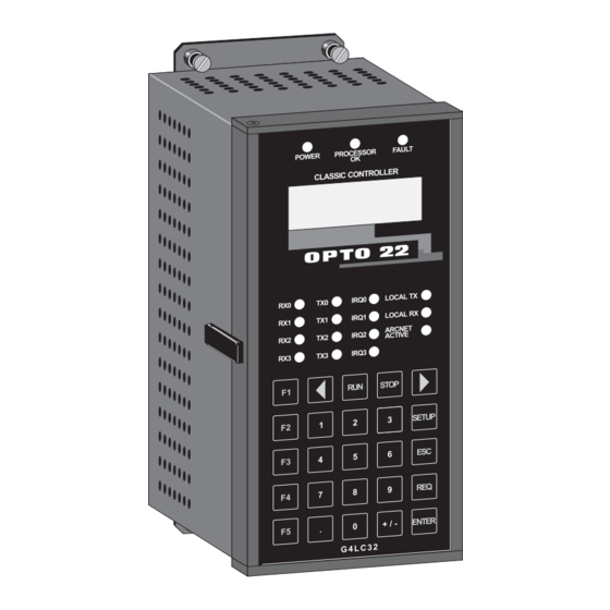
G4LC32 Front Panel Processor Status LEDs At the top of the G4LC32 front panel are three LED status indicators. Their function is as follows: POWER The red POWER LED comes on whenever 5 VDC power to the G4LC32 is above 4.85 VDC. -
Page 16: Lcd Display
During SETUP, the display is used to prompt you to enter the setup parameters from the keyboard. If you are running Cyrano 200 or OptoControl and you have downloaded the terminal task to the G4LC32, then the display is used to show parameters from your application’s program, such as the value of a variable, the status of an I/O point, etc. -
Page 17: Messages
In this case the keyboard is only used to enter setup parameters for the G4LC32. See the section on Front Panel Setup for the use of keyboard and display to enter and/or change setup parameters. -
Page 18: Communication Status Leds
This red LED is ON whenever there is communication on the ARCNET Bus and the ACTIVE G4LC32 is an active node. FRONT PANEL SETUP You can use the front panel display and keyboard to perform a setup for the G4LC32. Setup lets you view or change the following functions: Host port designation. Communication protocol. -
Page 19: View Mode
REQ key puts you in the VIEW MODE. Pressing the ENTER key puts you in the CHANGE MODE. View Mode From this mode you can display all of the G4LC32 setup parameters. The first display that you get when you enter the VIEW MODE will be similar to the following:... -
Page 20: Change Mode
SETUP MODE. ENTER Change Mode From this mode you can change any or all of the G4LC32 setup parameters. The first display that you get when you enter the CHANGE MODE will be the following: CHANGE MODE: <î>... - Page 21 HOST PORT. If you choose to change the HOST PORT, then ENTER press the left/right arrow keys to select a different port. Your choices are: COM0: COM1: COM2: COM3: ARCNET G4LC32 User’s Guide...
- Page 22 Repeat the process for each COM port. Baud rate choices are: 1,200 2,400 4,800 9,600 19.2K 38.4K 76.8K 115.2K Address The next display shows the current address setting in the bottom left corner. PROCESSOR ADDRESS MUST BE BETWEEN 1 AND 255 G4LC32 User’s Guide...
- Page 23 CONFIGURATION The address shown above may be different depending upon how your G4LC32 was previously configured. The factory default is 1. Just press the key if you do not choose to change the address. If you want to change the ENTER address, then enter a new value from the keyboard.
- Page 24 RUN FROM ROM Application programs are downloaded from your PC workstation to battery backed up RAM in the G4LC32 with the Cyrano Debugger. The factory default setting is for programs to RUN from RAM. Select RUN from RAM to make the controller run the program found in RAM on power up.
-
Page 25: Communication Switches
Unreliable communications will result. RS-422/485 Switch Settings The switches for terminating the G4LC32 RS-422/485 communications lines are located inside the unit, just behind the front panel. The controller has provisions for two-wire or four-wire communications. Two-wire communications is half duplex, where the transmitter is always off unless a message is being sent. - Page 26 CONFIGURATION G4LC32 Inside Panel G4LC32 User’s Guide 3-12...
-
Page 27: Installation
CHAPTER 4 INSTALLATION DIMENSIONS The following figure shows the outline and mounting dimensions of the G4LC32 Model 200 Processor. G4LC32 Model 200 Processor G4LC32 User’s Guide... -
Page 28: Mounting
INSTALLATION MOUNTING The G4LC32 controller has four captive screws for mounting. It can be mounted on the mounting panel included with Opto 22 P/N’s G4LPANEL (for local application), G4RPANEL (for remote application), or on a custom made panel. The following illustration shows the recommended mounting location on the Opto 22 panels. -
Page 29: Power Connections
POWER CONNECTIONS The G4LC32 power requirements are 5 VDC @ 2 A and are made to the 7-position power receptacle on the controller. If you are using an Opto 22 power supply, P/N G4PS245, it will have the proper mating plug attached. If you are using an alternate power supply, you can use a plug by Phoenix Contact, P/N MVSTBW 2,5/7-ST-5,08. -
Page 30: Ram And Flash Eprom Installation
The RAM and Flash EPROMs are found on a circuit board underneath the communications board. You can expand the G4LC32’s RAM from 512 KB to 4 MB, and its Flash EPROM size from 512 KB to 1 MB. To do this, use RAM and Flash EPROM chips specified in the tables on the next page. - Page 31 Remove the 34-pin ribbon cable (local cable) from the mother board by pressing down the release tabs. Pull out the G4LC32 mother board. The diagram on the next page shows the RAM, expansion RAM, and Flash EPROM locations on the mother board.
- Page 32 INSTALLATION The following tables describe memory size jumpering for the G4LC32. RAM Jumpers Jumper configure the RAM size. The factory default size is 512 KB. RAM chips go in sockets U1, U2, U3, U4, and expansion RAM chips go in sockets U5, U6, U7, and U8.
-
Page 33: Display Eprom Installation
Remove the power connector to the controller if it is attached. Remove the four screws which attach the communications board to the controller. Gently pull out the communications board. Press the connector tabs to release the front panel cable. G4LC32 User’s Guide... - Page 34 Continue sliding out the display circuit board to expose the display EPROM. 10. Observe anti-static precautions and carefully remove the EPROM. 11. Install the new EPROM. 12. Reverse the preceding steps to restore the controller. Display EPROM Location G4LC32 User’s Guide...
-
Page 35: Communications And Cables
Can be used as host ports The G4LC32 and remote I/O units (or any RS-485 device) can be separated by distances to 3,000 ft. (even longer distance with an AC38 repeater). A single shielded twisted-pair of wire provides communications over a RS-422/485 communication network to up to 100 (256 with repeaters) remote I/O units. - Page 36 RS-232 Cables Cables suitable for RS-232 wiring are: Belden #8132 (4-conductor #28 gauge) Belden #8133 (6-conductor #28 gauge) Belden #8134 (8-conductor #28 gauge) Belden #8102 (4-conductor #24 gauge) Belden #8103 (6-conductor #24 gauge) Belden #8104 (8-conductor #24 gauge) G4LC32 User’s Guide...
-
Page 37: Connectors
COMMUNICATIONS AND CABLES Connectors Green Pluggable 7 Position Terminal Mini-Plug Used for G4LC32 COM0, COM1, COM2, and COM3 Manufacturer: Phoenix Contact P/N MCVR 1,5/7-ST-3,81 Green Pluggable 7 Position Terminal Plug Used for G4LC32 Power Connections Manufacturer: Phoenix Contact P/N MVSTBW 2,5/7-ST-5,08 9-pin subminiature ‘D’... - Page 38 Common Ground (GND) Receive Plus (RX +) Receive Minus (RX -) Interrupt Plus (IRQ +) Interrupt Minus (IRQ -) RS-232 Only Fused +5V Transmit (TX) Receive (RX) Request-to-Send (RTS) Clear-to-Send (CTS) DTR (pullup to +9V) Ground (GND) G4LC32 User’s Guide...
-
Page 39: Fusing For Rs-232 +5V
A +5 VDC fused source is available from COM0 and COM1 on Pin 1. Fuse F1 is for COM0 and fuse F2 is for COM1. The fuse is rated at 1 A, but the maximum load should be no more than 0.5 A. The replacement part number for this fuse is Opto 22 FUSE01G4 (Wickman P/N 19373A). Fuse Locations... -
Page 40: Connections To A Host Pc
2-wire Mode Using an AC37 If you are using an Opto 22 AC37, the cable will have a male, 9-pin ‘D’ shell connector at the PC end and a pluggable terminal block on the Mistic controller end. See the diagram below for wiring. - Page 41 Make RS-232 communication connections to a Host PC by using COM0 or COM1 on the controller. COM0 is commonly used for this connection. See the following diagram to connect the G4LC32 to an AT type host computer. Verify pin connections at the host computer are the same as called out in the diagram.
- Page 42 Connections to a Remote Interface (G4IOR)The following diagram shows a typical 2-wire, shielded connection from COM1 on the G4LC32 to the G4IOR Remote Interface. Connect Pin 1 (TX/RX+) to G4IOR “TH+”, Pin 2 (TX/RX-) to G4IOR “TH-”, and Pin 3 to “COM”. If you are using the interrupt lines, connect Pin 6 to “IRQ+” and Pin 7 to “IRQ-”.
-
Page 43: Local Communications
The Local Bus is a high speed parallel interface communicating over 1.4 megabi•ts per second and can be up to 200 ft. in length. It connects the G4LC32 controller to local digital and analog I/O units. The following table lists some of the Local Bus specifications. -
Page 44: Wiring
Overview The G4LC32 has an ARCNET connection that can be used as a host port to a computer. You can use an IBM PC to develop your application with Cyrano 200 or OptoControl, and then download and debug it on any of the G4LC32’s that are connected to the ARCNET bus. -
Page 45: Cables And Connectors
100 ft. (or to Host PC) Cables and Connectors The following is suggested cable wire and connectors to make your custom ARCNET cable. Cable Wire: RG62A/U Coaxial Cable Manufacturer: Belden Connectors: BNC Connectors Terminators: 93 Ohms 5-11 G4LC32 User’s Guide... - Page 46 COMMUNICATIONS AND CABLES 5-12 G4LC32 User’s Guide...
-
Page 47: Software And Firmware
RAM AND FLASH EPROMS The G4LC32 has 512 KB of battery backed RAM and is expandable to 4 MB. It also has 512 KB of Flash EPROM and is expandable to 1 MB. For installation instructions, refer to the “RAM and Flash EPROM Installation” section. - Page 48 SOFTWARE AND FIRMWARE G4LC32 User’s Guide...
-
Page 49: G4Lc32 Hardware Specifications
CHAPTER 7 G4LC32 HARDWARE SPECIFICATIONS Motorola 68020 32-bit microprocessor Motorola 68882 floating point math coprocessor CPU Clock Frequency 16.67 MHz FLASH EPROM 512 KB (expandable to 1 MB) 512 KB (expandable to 4 MB), with battery backup Watchdog timer Standard, hardware... - Page 50 G4LC32 User’s Guide...
Need help?
Do you have a question about the G4LC32 and is the answer not in the manual?
Questions and answers