
Subscribe to Our Youtube Channel
Related Manuals for Abit AN8 32X


Summary of Contents for Abit AN8 32X
- Page 1 AN8 32X AMD Athlon 64/64FX/64x2 Dual Core System Board Socket 939 User’s Manual 4310-0000-15 Rev. 2.00...
- Page 2 No part of this manual may be reproduced, transmitted or transcribed without the expressed written permission of the manufacturer and authors of this manual. If you do not properly set the motherboard settings, causing the motherboard to malfunction or fail, we cannot guarantee any responsibility. AN8 32X...
-
Page 3: Table Of Contents
Table of Contents Chapter 1. Introduction ................1-1 1-1. Features & Specifications ................1-1 1-2. Layout Diagram ..................1-3 Chapter 2. Hardware Setup..............2-1 2-1. Install The Motherboard................2-1 2-2. Install CPU, Heatsink and Fan Assembly..........2-2 2-3. Install System Memory ................2-4 2-4. Install Graphics Card(s) ................2-6 2-5. - Page 4 Install Silicon Image 3132 RAID Driver ........D-1 Appendix E. Install Cool’n’Quiet Driver ............. E-1 Appendix F. Install USB 2.0 Driver ..............F-1 Appendix G. Install ABIT µGuru Utility ..............G-1 Appendix H. Generate Raid Floppy Disk .............H-1 Appendix I. POST Code Definition ..............I-1 Appendix J.
-
Page 5: Chapter 1. Introduction
Introduction Chapter 1. Introduction 1-1. Features & Specifications 1. CPU • Supports AMD Athlon 64/64FX/64x2 Dual Core 939-pin K8 CPU with 2GHz system bus using Hyper Transport Technology • Supports AMD K8 CPU Cool ‘n’ Quiet Technology 2. Chipset ® •... - Page 6 1x AUDIO2 connector (Mic-In, Line-In, Line-Out) • 4x USB 2.0 connector • 1x RJ-45 LAN connector • 1 x IEEE1394 port 12. Miscellaneous • ATX form factor: 305 x 245 mm Specifications and information contained herein are subject to change without notice. AN8 32X...
-
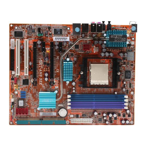
Page 7: Layout Diagram
Introduction 1-2. Layout Diagram User’s Manual... - Page 8 Chapter 1 Chapter 1 AN8 32X AN8 32X...
-
Page 9: Chapter 2. Hardware Setup
Hardware Setup Chapter 2. Hardware Setup Before the Installation: Turn off the power supply switch (fully turn off the +5V standby power), or disconnect the power cord before installing or unplugging any connectors or add-on cards. Failing to do so may cause the motherboard components or add-on cards to malfunction or damaged. 2-1. -
Page 10: Install Cpu, Heatsink And Fan Assembly
5. Place the heatsink and fan assembly onto the socket. the retention frame. Match the heatsink clip with the socket mounting lug. Hook the spring clip to the mounting lug. AN8 32X... - Page 11 Hardware Setup 6. On the other side, push the retention clip 8. Attach the four-pin power plug from the straight down to lock into the plastic lug on the heatsink and fan assembly to the CPU FAN retention frame. connector. For detailed information on how to install your heatsink and fan assembly, please refer to the instruction manual that came packed with the...
-
Page 12: Install System Memory
Single rank Single rank Single rank DDR333 DDR400 Channel) Single rank Single rank Double rank Double rank DDR200 DDR400 Double rank Double rank Single rank Single rank DDR200 DDR400 Double rank Double rank Double rank Double rank DDR200 DDR333 AN8 32X... - Page 13 Hardware Setup To reach the performance of Dual Channel DDR, the following rules must be obeyed: • When installing TWO DIMM modules: Install DIMM modules of the same type and size for slots [DIMM1]+[DIMM2] or slots [DIMM3]+[DIMM4]. • When installing FOUR DIMM modules: Install DIMM modules of the same type and size for slots [DIMM1]+[DIMM2], and slots [DIMM3]+[DIMM4].
-
Page 14: Install Graphics Card(S)
Make sure your power supply unit is sufficient to provide the minimum power required. 1. Insert the two graphics cards into PCIEXP1 2. There are goldfingers on your SLI Graphics and PCIEXP2 slots on the motherboard. Cards reserved for the SLI Bridge Connector. AN8 32X... - Page 15 Hardware Setup 3. Locate the SLI Bridge Connector in the 6. Insert the SLI bracket into the bracket slot package. between the graphics cards. Secure the SLI bracket and the graphics cards to the chassis with screws. NOTE: The OTES SLIpstream that packed in the package is optional.
-
Page 16: Connectors, Headers And Switches
2A +5VSB capacity at least for supporting wake-up features. The auxiliary 12V power connector [ATX4P1] provides an additional power source for devices added on PCI Express slots. It is highly recommended to attach 12V power from the power supplier for the best system stability. AN8 32X... -
Page 17: Fan Power Connectors
Hardware Setup (2). FAN Power Connectors These connectors each provide power to the cooling fans installed in your system. • CPUFAN1: CPU Fan Power Connector • SYSFAN1: System Fan Power Connector • NBFAN1: Chipset Fan Power Connector • AUXFAN1, AUXFAN2: Auxiliary Fan Power Connector WARNING: These fan connectors are not jumpers. -
Page 18: Front Panel Switches & Indicators Headers
Connects to the Suspend LED cable (if there is one) of chassis front panel. • PWR-ON (Pin 6, 8): Connects to the Power Switch cable of chassis front panel. • PLED (Pin 16, 18, 20): Connects to the Power LED cable of chassis front panel. AN8 32X... -
Page 19: Additional Usb Port Headers
Hardware Setup 2-11 (5). Additional USB Port Headers These headers each provide 2 additional USB 2.0 ports connection through a USB cable designed for USB 2.0 specifications. Pin Assignment Pin Assignment Data0 - Data1 - Data0 + Data1 + Ground Ground (6). -
Page 20: Wake-Up Header
Pin 1-2 shorted (default): Disable wake-up function support at FP-USB2 port. Pin 2-3 shorted: Enable wake-up function support at FP-USB2 port. • FP-PWR3: Pin 1-2 shorted (default): Disable wake-up function support at FP-USB3 port. Pin 2-3 shorted: Enable wake-up function support at FP-USB3 port. AN8 32X... -
Page 21: Floppy And Ide Disk Drive Connectors
Hardware Setup 2-13 (8). Floppy and IDE Disk Drive Connectors The FDC1 connector connects up to two floppy drives with a 34-wire, 2-connector floppy cable. Connect the single end at the longer length of ribbon cable to the FDC1 on the board, the two connectors on the other end to the floppy disk drives connector. -
Page 22: Serial Ata Connectors
(9). Serial ATA Connectors These connectors are provided to attach one Serial ATA device at each channel via Serial ATA cable. (10). GURU Clock Connection Header This header is reserved for connecting ABIT’s exclusive GURU Clock or GURU Panel. AN8 32X... -
Page 23: Pci Express X1 Slots
Hardware Setup 2-15 (11). PCI Express x1 Slots These slots are used to attach the next generation of I/O architecture. (12). PCI Express x16 Slot This slot is used to attach the next generation of graphics architecture. User’s Manual... -
Page 24: Front Panel Audio Connection Header
Audio Mic. Bias Speaker Out Right Speaker Out Right Channel Channel Return Speaker Out Left Speaker Out Left Channel Channel Return (14). Internal Audio Connectors These connectors connect to the audio output of internal CD-ROM drive or add-on card. AN8 32X... -
Page 25: Post Code Display
POST Code in address 80h to find out where the problem lies. This LED device also displays the “POST” Code of AC2005, an “uGuru” chipset developed exclusively by ABIT computer. NOTE: The decimal point lights up when executing the AC2005 POST action. -
Page 26: Back Panel Connectors
Line-Out: Connects to the front left and front right channel in the 7.1-channel or regular 2-channel audio system. • IEEE1: Connects to devices of IEEE1394 protocol • LAN1: Connects to Local Area Network. • USB1/USB2: Connects to USB devices such as scanner, digital speakers, monitor, mouse, keyboard, hub, digital camera, joystick etc. AN8 32X... -
Page 27: Chapter 3. Bios Setup
BIOS Setup Chapter 3. BIOS Setup This motherboard provides a programmable EEPROM that you can update the BIOS utility. The BIOS (Basic Input/Output System) is a program that deals with the basic level of communication between processor and peripherals. Use the BIOS Setup program only when installing motherboard, reconfiguring system, or prompted to “Run Setup”. - Page 28 Press these buttons to choose, in the main menu, the option you want to confirm or to modify. F10: When you have completed the setup of BIOS parameters, press this button to save these parameters and to exit the BIOS Setup menu. Save current setting as a profile Load previous saved profile AN8 32X...
-
Page 29: Μguru Utility
There are two setup menus in this µGuru utility. You may switch between these two by clicking the left or right arrow key on keyboard: OC Guru: µGuru Utility V1.00 OC Guru ABIT EQ AMD Athlon(tm) 64 X2 Dual Core Processor 3800+ Item Help CPU Operating Speed 2000(200) X - Multiplier Factor x10.0... - Page 30 PC Up Time Total 107 Hours PC Power Cycles 532 Cycles AC Power On Total Time 288 Hours AC Power Cycles 228 Cycles ↑↓ → ←:Move Enter:Select +/-/PU/PD:Value F10:Save ESC:Exit These items display the power cycle statistics for each element. AN8 32X...
-
Page 31: Temperature Monitoring
BIOS Setup ABIT EQ: Click right-arrow <→> key to switch from OC Guru setup menu to ABIT EQ setup menu: µGuru Utility V1.00 OC Guru ABIT EQ Item Help ABIT EQ Beep Control Enabled ► Temperature Monitoring Press Enter ► Voltage Monitoring Press Enter ►... - Page 32 5.00 V 6.00 V 4.00 V (*)ATX +3.3V 3.39 V 3.95 V 2.65 V (*)ATX 5VSB 5.11 V 6.00 V 4.00 V ↑↓ → ←:Move Enter:Select +/-/PU/PD:Value F10:Save ESC:Exit All Voltages: These items display the voltage of each element. AN8 32X...
- Page 33 NOTE: The value of high limit must be set above the one of low limit. Fan Speed Monitoring: Click <Enter> key to enter its submenu: µGuru Utility V1.00 OC Guru ABIT EQ Fan Speed Monitoring Reading Shutdown Beep Low Limit...
- Page 34 This item sets the high and low temperature limits desired for the fan speed control. DC Fan Voltage High/Low: This item sets the high and low voltage limits for the fan. NOTE: The value of high limit must be set above the one of low limit. AN8 32X...
-
Page 35: Standard Cmos Features
BIOS Setup 3-2. Standard CMOS Features Phoenix – Award BIOS CMOS Setup Utility Standard CMOS Features Date (mm:dd:yy) Thu. Dec 20 2005 Item Help Time (hh:mm:ss) 12 : 34 : 56 ► IDE Channel 1 Master [Maxtor 6B160P0] ► IDE Channel 1 Slave [ None] ►... - Page 36 HDD automatically. Capacity: This item displays the approximate capacity of the disk drive. Usually the size is slightly greater than the size of a formatted disk given by a disk-checking program. Cylinder: This item configures the number of cylinders. AN8 32X...
- Page 37 BIOS Setup 3-11 Head: This item configures the number of read/write heads. Precomp: This item displays the number of cylinders at which to change the write timing. Landing Zone: This item displays the number of cylinders specified as the landing zone for the read/write heads. Sector: This item configures the number of sectors per track.
-
Page 38: Advanced Bios Features
BIOS will skip this test. The default setting is Disabled. Boot Up NumLock Status: This item determines the default state of the numeric keypad at system booting up. [On]: The numeric keypad functions as number keys. [Off]: The numeric keypad functions as arrow keys. AN8 32X... - Page 39 BIOS Setup 3-13 Security Option: This item determines when the system will prompt for password - every time the system boots or only when it enters the BIOS setup. [Setup]: The password is required only when accessing the BIOS Setup. [System]: The password is required each time the computer boots up.
-
Page 40: Advanced Chipset Features
NB<--SB HT Speed: This item selects SB to NB LDT Bus Frequency. K8<->NB HT Width: This item selects the LDT Bus Width between CPU and NB. NB<->SB HT Width: This item selects the LDT Bus Width between NB and SB. AN8 32X... -
Page 41: Dram Configuration
BIOS Setup 3-15 DRAM Configuration: Click <Enter> key to enter its submenu: Phoenix – Award BIOS CMOS Setup Utility DRAM Configuration DRAM Timing Selectable Auto Item Help X - DRAM Clock Auto X - CAS Latency Time Auto X - Row Cycle Time Auto X - Row Refresh Cycle Time Auto... - Page 42 This item allows you to Enable or Disable the SSE/SSE2 (Streaming SIMD Extensions) instruction set. The default setting is Enabled. System BIOS Cacheable: Two options are available: Disabled or Enabled. When you select Enabled, you get faster system BIOS executing speed via the L2 cache. AN8 32X...
-
Page 43: Integrated Peripherals
BIOS Setup 3-17 3-5. Integrated Peripherals Phoenix – Award BIOS CMOS Setup Utility Integrated Peripherals ► OnChip IDE/RAID Function Press Enter Item Help Init Display First PCIe OnChip USB V1.1+V2.0 - USB Keyboard Support Disabled - USB Mouse Support Disabled OnChip Audio Controller Auto OnChip LAN Controller... -
Page 44: Ide Function Setup
This item selects the DMA mode for devices connected through IDE channels. IDE HDD Block Mode: This item enables or disables the IDE HDD Block Mode. Serial-ATA 1/2, Serial-ATA 3/4: This item enables or disables the on-chip SATA controller. AN8 32X... -
Page 45: Raid Config
BIOS Setup 3-19 RAID Config: Click <Enter> key to enter its submenu: Phoenix – Award BIOS CMOS Setup Utility RAID Config RAID Function Diaabled Item Help X - Serial-ATA 1 RAID Disabled X - Serial-ATA 2 RAID Disabled X - Serial-ATA 3 RAID Disabled X - Serial-ATA 4 RAID Disabled... - Page 46 This item enables or disables the OnBoard SATA controller. OnBoard SATA Mode: This item determines the mode for OnBoard Serial ATA. [IDE]: The on-chip Serial ATA served as IDE mode. [RAID]: The on-chip Serial ATA served as RAID mode. AN8 32X...
-
Page 47: Power Management Setup
BIOS Setup 3-21 3-6. Power Management Setup Phoenix – Award BIOS CMOS Setup Utility Power Management Setup ACPI Suspend Type S3(Suspend-to-RAM) Item Help - USB Resume from S3 Disabled Power Button Function Instant-Off Wakeup by PME# of PCI Disabled Wakeup by OnChip LAN Enabled Wakeup by Alarm Disabled... - Page 48 If the system’s power is off when AC power failure occurs, it will remain off when power returns. If the system’s power is on when AC power failure occurs, the system will power-on when power returns. AN8 32X...
-
Page 49: Pnp/Pci Configurations
BIOS Setup 3-23 3-7. PnP/PCI Configurations Phoenix – Award BIOS CMOS Setup Utility PnP/PCI Configurations Resources Controlled By Auto(ESCD) Item Help x IRQ Resources Press Enter PCI/VGA Pallete Snoop Disbaled PIRQ_0 Use IRQ No. Auto PIRQ_1 Use IRQ No. Auto PIRQ_2 Use IRQ No. -
Page 50: Load Fail-Safe Defaults
This option protects the BIOS configuration or restricts access to the computer itself. 3-11. Save & Exit Setup This option saves your selections and exits the BIOS setup menu. 3-12. Exit Without Saving This option exits the BIOS setup menu without saving any change. AN8 32X... -
Page 51: Appendix A. Install Nvidia Nforce Chipset Driver
Install nVidia nForce Chipset Driver Appendix A. Install nVidia nForce Chipset Driver NOTE: Please install this NVIDIA nForce Chipset driver first after having installed the Windows operating system. The installation procedures and screen shots in this section are based on the Windows XP operating system. - Page 52 Appendix A Click [Next]. Click [Next]. 7. Click [Next]. 10. Choose [Yes, I want to restart my computer now.], and click [Finish] to complete setup. 8. Click [Next]. AN8 32X...
-
Page 53: Appendix B. Install Realtek Audio Driver
Install Realtek Audio Driver Appendix B. Install Realtek Audio Driver The installation procedures and screen shots in this section are based on Windows XP operating system. For those of other OS, please follow its on-screen instruction. Insert the Driver & Utility CD into CD-ROM drive, it should execute the installation program automatically. - Page 54 Appendix B Appendix B AN8 32X AN8 32X...
-
Page 55: Appendix C. Install Silicon Image 3132 Sata Driver
Install Silicon Image 3132 SATA Driver Appendix C. Install Silicon Image 3132 SATA Driver The installation procedures and screen shots in this section are based on Windows XP operating system. For those of other OS, please follow its on-screen instruction. Insert the Driver &... - Page 56 Appendix C Appendix C AN8 32X AN8 32X...
-
Page 57: Appendix D. Install Silicon Image 3132 Raid Driver
Install Silicon Image 3132 RAID Driver Appendix D. Install Silicon Image 3132 RAID Driver The installation procedures and screen shots in this section are based on Windows XP operating system. For those of other OS, please follow its on-screen instructions. Insert the Driver &... - Page 58 Appendix D Click [Finish]. Click [Finish]. 6. Check the item “I accept the license Click [Finish]. agreement”. Click [Next] to go on next step. 7. Click [Next]. AN8 32X...
-
Page 59: Appendix E. Install Cool'n'quiet Driver
Install Cool’n’Quiet Driver Appendix E. Install Cool’n’Quiet Driver The installation procedures and screen shots in this section are based on Windows XP operating system. For those of other OS, please follow its on-screen instruction. Insert the Driver & Utility CD into CD-ROM drive, it should execute the installation program automatically. - Page 60 NOTE: For Windows 2000 or ME system, an AMD Cool ‘n’ Quiet tab will appear under “Power Options” when the Cool ‘n’ Quiet software for Windows 2000 and ME is installed. This must be set to “Automatic Mode” for Cool ‘n’ Quiet to be enabled. AN8 32X...
-
Page 61: Appendix F. Install Usb 2.0 Driver
Install USB 2.0 Driver Appendix F. Install USB 2.0 Driver NOTE: The installation for USB 2.0 driver for Windows XP or Windows 2000 is currently available by updating the latest Service Pack from Microsoft’s web site. User’s Manual... - Page 62 Appendix F AN8 32X...
-
Page 63: Appendix G. Install Abit Μguru Utility
CD to enter the installation menu. After entering the installation menu, move your cursor to the [ABIT Utility] tab. Click [ABIT µGuru]. The following screen appears. 3. Choose [Yes, I want to restart my computer now.], and click [Finish] to complete setup. - Page 64 Appendix G AN8 32X...
-
Page 65: Appendix H. Generate Raid Floppy Disk
If not, double-click the execution file at the main directory of this CD to enter the installation menu. After entering the installation menu, move your curser to [ABIT Utility] tab. Click one of the Generate Raid Floppy Disk items: [Generate NVRaid... - Page 66 Appendix H AN8 32X...
-
Page 67: Appendix I. Post Code Definition
POST Code Definition Appendix I. POST Code Definition AWARD POST Code Definitions POST Description (hex) Test CMOS R/W functionality Early chipset initialization: -Disable shadow RAM -Disable L2 cache (socket 7 or below) -Program basic chipset registers Detect memory -Auto-detection of DRAM size, type and ECC -Auto-detection of L2 cache (socket 7 or below) Expand compressed BIOS code to DRAM Call chipset hook to copy BIOS back to E000 &... - Page 68 4. On MP platform, adjust the cacheable range to smaller one in case the cacheable ranges between each CPU are not identical Initialize USB Test all memory (clear all extended memory to 0) Clear password according to H/W jumper (Optional) AN8 32X...
- Page 69 POST Code Definition Display number of processors (multi-processor platform) Display PnP logo Early ISA PnP initialization -Assign CSN to every ISA PnP device Initialize the combined Trend Anti-Virus code (Optional Feature) Show message for entering AWDFLASH.EXE from FDD (optional) 1. Initialize Init_Onboard_Super_IO 2.
- Page 70 Update keyboard LED & typematic rate 1. Build MP table 2. Build & update ESCD 3. Set CMOS century to 20h or 19h 4. Load CMOS time into DOS timer tick 5. Build MSIRQ routing table Boot attempt (INT 19h) AN8 32X...
- Page 71 POST Code Definition AC2005 POST Code Definition: POST Description (hex) Power On Sequence 8.1. Start power on sequence 8.2. Enable ATX power supply 8.3. ATX power supply ready 8.4. DDR voltage ready 8.5. Setup PWM for CPU core voltage 8.6. Assert PWM for CPU core voltage 8.7.
- Page 72 Appendix I Appendix I AN8 32X AN8 32X...
-
Page 73: Appendix J. Troubleshooting (Need Assistance
Troubleshooting (Need Assistance?) Appendix J. Troubleshooting (Need Assistance?) Q & A: Q: Do I need to clear the CMOS before I use a new motherboard to assemble my new computer system? A: Yes, we highly recommend that you clear the CMOS before installing a new motherboard. Please move the CMOS jumper from its default 1-2 position to 2-3 for a few seconds, and then back. - Page 74 Write down the sound card model, motherboard model, BIOS identification number on the technical support file (refer to main instructions), and describe the problem in the space provided. We will show you how to fill the “Technical Support Form”. AN8 32X...
- Page 75 To fill in this “Technical Support Form”, refer to the step-by-step instructions given below: . MODEL: Note the model number given in your user’s manual. Example: AN8 32X . Motherboard model number (REV): Note the motherboard model number labeled on the motherboard as “REV:*.**”.
-
Page 76: Technical Support Form
Technical Support Form Company Name: Phone Number: Contact Person: Fax Number: E-mail Address: Model BIOS ID # Motherboard Model No. DRIVER REV OS/Application Hardware Name Brand Specifications IDE1 IDE2 IDE1 CD-ROM-Drive IDE2 System Memory ADD-ON CARD Problem Description: AN8 32X... -
Page 77: Appendix K. How To Get Technical Support
Also please make sure you have the latest drivers from your peripheral card makers! 3. Check the ABIT Technical Terms Guide and FAQ on our website. We are trying to expand and make the FAQs more helpful and information rich. Let us know if you have any suggestions. - Page 78 They should have reasonable return or refund policies. How they serve you is also a good reference for your next purchase. 6. Contacting ABIT. If you feel that you need to contact ABIT directly you can send email to the ABIT technical support department. First, please contact the support team for the branch office closest to you.
- Page 79 Unit 3, 24-26 Boulton Road, Stevenage, Herts SG1 4QX, UK Tel: 44-1438-228888 Fax: 44-1438-226333 E-mail: sales@abitcomputer.co.uk Germany and Benelux (Belgium, AMOR Computer B.V. (ABIT's European Office) Jan van Riebeeckweg 15, 5928LG, Venlo, Netherlands, Luxembourg), The Netherlands France, Italy, Spain, Portugal, Greece, Denmark, Norway, Tel: 31-77-3204428...
- Page 80 Please contact the reseller from whom you bought the product. You should be able to get RMA service there. 8. Reporting Compatibility Problems to ABIT. Because of tremendous number of email messages we receive every day, we are forced to give greater weight to certain types of messages than to others.
Need help?
Do you have a question about the AN8 32X and is the answer not in the manual?
Questions and answers