Table of Contents
Advertisement
Advertisement
Table of Contents

Related Manuals for Abit Socket 462 System Board


Summary of Contents for Abit Socket 462 System Board
- Page 1 Socket 462 System Board User’s Manual 4200-0390-02 Rev. 1.00...
- Page 2 Copyright and Warranty Notice The information in this document is subject to change without notice and does not represent a commitment on part of the vendor, who assumes no liability or responsibility for any errors that may appear in this manual. No warranty or representation, either expressed or implied, is made with respect to the quality, accuracy or fitness for any particular part of this document.
-
Page 3: Table Of Contents
Table Of Contents AN7 快速安裝指引 ................... 2 AN7 のクイックインストールガイド ........... 4 AN7 Schnellinstallationsanleitung ............6 AN7 Guide d’Installation Rapide ............8 Краткое руководство по установке AN7........... 10 Guida all’installazione veloce Scheda madre AN7 ......12 Chapter 1. Introduction ................1-1 1-1. - Page 4 Exit Without Saving................3-23 Appendix A. Install NVIDIA nForce Chipset Driver .......... A-1 Appendix B. Install Serial ATA RAID Driver............B-1 Appendix C. Install ABIT µGuru Driver.............. C-1 Appendix D. POST Code Definition ..............D-1 Appendix E. Troubleshooting (Need Assistance?)..........E-1 Appendix F.
- Page 5 User’s Manual...
-
Page 6: An7 快速安裝指引
AN7 快速安裝指引 AN7 快速安裝指引 處理器的安裝 Zero Insertion Force, ZIF Socket 462 AMD Socket A Socket A Socket 462 “Socket 462” 注意:... - Page 7 AN7 快速安裝指引 將主機板安裝到機殼上 安裝記憶體模組 DIMM DIMM DIMM DIMM DIMM DIMM DIMM DIMM DIMM DIMM 注意: 連接器、連接頭以及附加卡的安裝 SCSI 將電源供應器的電源線連接頭與主機板上的 ATX12V 電源接頭連接起來 ATX12V BIOS 的設定 BIOS User’s Manual...
-
Page 8: An7 のクイックインストールガイド
AN7 のクイックインストールガイド AN7 のクイックインストールガイド Socket 462 AMD Socket A CPU Socket A Socket 462 2. CPU “Socket 462”... - Page 9 AN7 のクイックインストールガイド DIMM 2. DIMM DIMM DIMM 5. DIMM SCSI ATX12V ATX12V ご BIOS ハ ウ 了 BIOS Setup 移 メ User’s Manual...
-
Page 10: An7 Schnellinstallationsanleitung
AN7 Schnellinstallationsanleitung AN7 Schnellinstallationsanleitung Beziehen Sie sich bitte für detaillierte Informationen über diese Hauptplatine auf die vollständige Version des Benutzerbuchs. Diese Schnellinstallationsanleitung ist für erfahrene Systemaufbauer gedacht. Ist es Ihr erster Versuch ein Computersystem aufzubauen, dann empfehlen wir Ihnen zuerst das vollständige Benutzerhandbuch zu lesen oder einen Techniker zum Aufbauen des Systems zu Hilfe zu holen. - Page 11 AN7 Schnellinstallationsanleitung Achtung: Vergessen Sie nicht, die korrekte Busfrequenz und -Multiplikator für Ihren Prozessor einzustellen. Installieren der Hauptplatine im Gehäuse Nach der Installation des Prozessors können Sie anfangen die Hauptplatine im Computergehäuse zu befestigen. Die meisten Gehäuse haben eine Bodenplatte, auf der sich eine Reihe von Befestigungslöcher befinden, mit deren Hilfe Sie die Hauptplatine sicher verankern können und zugleich Kurzschlüsse verhindern.
-
Page 12: An7 Guide D'installation Rapide
AN7 Guide d’Installation Rapide AN7 Guide d’Installation Rapide Pour des informations relatives à cette carte mère plus détaillées, veuillez vous référer à notre version complète du manuel utilisateur. Ce guide d’installation rapide est créé pour les assembleurs système expérimentés. S’il s’agit de votre premier essai pour installer un ordinateur, nous vous suggérons de lire d’abord le manuel en version complète ou de demander l’aide d’un technicien pour vous aider à... - Page 13 AN7 Guide d’Installation Rapide Attention: N’oubliez pas de programmer la fréquence de bus correcte et le multiple pour votre processeur. Installer la Carte Mre dans le Châssis Une fois que vous aurez installé le processeur sur la carte mère, vous pourrez commencer à fixer la carte mère sur le châssis.
-
Page 14: Краткое Руководство По Установке An7
Краткое руководство по установке AN7 Краткое руководство по установке AN7 Более подробные сведения о материнской плате приведены в руководстве пользователя. Краткое руководство по установке предназначено для опытных специалистов. Если вы собираете компьютер впервые, ознакомьтесь сперва с руководством пользователя или попросите техника помочь... - Page 15 Краткое руководство по установке AN7 Внимание: Установите соответствующие частоту и кратность шины процессора. Установка материнской платы в корпус После установки процессора на материнскую плату можно начинать установку материнской платы в корпус. Большая часть корпусов оборудована основанием, в котором проделаны монтажные отверстия, которые позволяют надежно закрепить материнскую плату и предотвратить короткие...
-
Page 16: Guida All'installazione Veloce Scheda Madre An7
Guida all’installazione veloce Scheda madre AN7 Guida all’installazione veloce Scheda madre AN7 Per maggiori e dettagliate informazioni su questa scheda madre si prega di fare riferimento alla versione integrale del Manuale utente. Questa guida all’installazione veloce è intesa per costruttori esperi di sistemi. - Page 17 Guida all’installazione veloce Scheda madre AN7 Installazione della scheda madre sul telaio Dopo avere installato il processore sulla scheda madre si può iniziare a fissare la scheda madre sul telaio. Innanzi tutto è necessario fissare la scheda madre al telaio. La maggior parte dei telai ha una base sulla quale sono presenti diversi fori di montaggio che permettono di fissare in modo accurato la scheda madre e, allo stesso tempo, di prevenire corto circuiti.
- Page 18 14 14...
-
Page 19: Chapter 1. Introduction
Accelerated Graphics Port connector supports AGP 8X/4X (0.8V/1.5V) 3. Memory • 3x 184-pin DIMM sockets • Supports 2 DIMM Un-buffered DDR 400 (Max. 2GB) • Supports 3 DIMM Un-buffered DDR 200/266/333 (Max. 3GB) 4. ABIT Engineered • ABIT µGuru Technology • ABIT SoftMenu Technology •... - Page 20 Chapter 1 • 2x SATA 150 connectors • 1x USB header • 1x IEEE 1394a header • 1x CD-IN, 1x AUX-IN header 10. Back Panel I/O • 1x PS/2 keyboard, 1x PS/2 mouse • 1x Serial port connector, 1x Parallel port connector •...
-
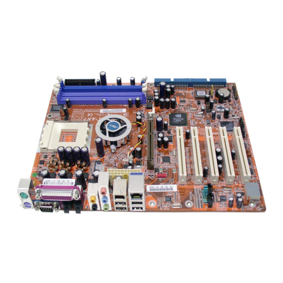
Page 21: Layout Diagram
Introduction 1-2. Layout Diagram User’s Manual... - Page 22 Chapter 1...
-
Page 23: Chapter 2. Hardware Setup
Hardware Setup Chapter 2. Hardware Setup Before the Installation: Turn off the power supply switch (fully turn off the +5V standby power), or disconnect the power cord before installing or unplugging any connectors or add-on cards. Failing to do so may cause the motherboard components or add-on cards to malfunction or damaged. 2-1. - Page 24 Chapter 2 This motherboard provides a ZIF (Zero Insertion Force) Socket 462 to install AMD Socket A CPU. The CPU you bought should have a kit of heatsink and cooling fan along with. If that’s not the case, buy one specially designed for Socket A. Please refer to the figure shown here to install CPU and heatsink.
-
Page 25: Install System Memory
Hardware Setup 2-3. Install System Memory This motherboard provides 3 184-pin DDR DIMM sites for memory expansion available from minimum 128MB to maximum 3GB. Table 2-1. Valid Memory Configurations Bank Memory Module Total Memory Bank 0, 1 (DIMM1) 128, 256, 512MB, 1GB 128MB ~ 1GB Bank 2, 3 (DIMM2) 128, 256, 512MB, 1GB... -
Page 26: Connectors, Headers And Switches
Chapter 2 2-4. Connectors, Headers and Switches Here we will show you all of the connectors, headers and switches, and how to connect them. Please read the entire section for necessary information before attempting to finish all the hardware installation inside the computer chassis. -
Page 27: Fan Connectors
Hardware Setup (2). FAN Connectors These 3-pin connectors each provide power to the cooling fans installed in your system. • CPUFAN1: CPU Fan • NBFAN1: Chipset Fan • SYSFAN1: System Fan • FAN4, FAN5: Auxiliary Fan WARNING: These fan connectors are not jumpers. DO NOT place jumper caps on these connectors. User’s Manual... -
Page 28: Cmos Memory Clearing Header
Chapter 2 (3). CMOS Memory Clearing Header This header uses a jumper cap to clear the CMOS memory. • Pin 1-2 shorted (default): Normal operation. • Pin 2-3 shorted: Clear CMOS memory. WARNING: Turn the power off first (including the +5V standby power) before clearing the CMOS memory. -
Page 29: Wake-Up Header
Hardware Setup (4). Wake-up Header These headers use a jumper cap to enable/disable the wake-up function. • KBPWR1: Pin 1-2 shorted (default): Disable wake-up function support at Keyboard/Mouse port. Pin 2-3 shorted: Enable wake-up function support at Keyboard/Mouse port. • USBPWR1: Pin 1-2 shorted (default): Disable wake-up function support at USB1 port. -
Page 30: Front Panel Switches & Indicators Headers
Chapter 2 (5). Front Panel Switches & Indicators Headers This header is used for connecting switches and LED indicators on the chassis front panel. Watch the power LED pin position and orientation. The mark “+” align to the pin in the figure below stands for positive polarity for the LED connection. -
Page 31: Additional Usb Port Header
Hardware Setup (6). Additional USB Port Header This header provides 2 additional USB 2.0 ports connection through an USB cable designed for USB 2.0 specifications. Pin Assignment Pin Assignment Data0 - Data1 - Data0 + Data1 + Ground Ground User’s Manual... -
Page 32: Additional Ieee1394 Port Header
2-10 Chapter 2 (7). Additional IEEE1394 Port Header This header provides one additional IEEE1394 port connection through an extension cable and bracket. Pin Assignment Pin Assignment TPA0 + TPA0 - TPB0 + TPB0 - +12V +12V... -
Page 33: Front Panel Audio Connection Header
Hardware Setup 2-11 (8). Front Panel Audio Connection Header This header provides the connection to audio connector at front panel. • To use the audio connector at front panel, remove all the jumpers on this header, and then connect to front panel by the extension cable provided with the chassis. •... -
Page 34: Internal Audio Connectors
2-12 Chapter 2 (9). Internal Audio Connectors These connectors connect to the audio output of internal CD-ROM drive or add-on card. -
Page 35: Accelerated Graphics Port Slot
Hardware Setup 2-13 (10). Accelerated Graphics Port Slot This slot supports an optional AGP graphics card up to AGP 8X mode. Please refer to our Web site for more information on graphics cards. ATTENTION: This motherboard does not support 3.3V AGP cards. Use only 1.5V or 0.8V AGP cards. User’s Manual... -
Page 36: Floppy Disk Drive Connector
2-14 Chapter 2 (11). Floppy Disk Drive Connector This connector supports two standard floppy disk drives via a 34-pin 34-conductor ribbon cable. Connecting the Floppy Disk Drive Cable: 1. Install one end of the ribbon cable into the FDC1 connector. The colored edge of the ribbon cable should be aligned with pin-1 of FDC1 connector. -
Page 37: Ide Connectors
Hardware Setup 2-15 (12). IDE Connectors This motherboard provides two IDE ports to connect up to four IDE drives at Ultra DMA mode by Ultra ATA/66 ribbon cables. Each cable has 40-pin 80-conductor and three connectors, providing two hard drives connection with motherboard. Connect the single end (blue connector) at the longer length of ribbon cable to the IDE port on motherboard, and the other two ends (gray and black connector) at the shorter length of the ribbon cable to the connectors on hard drives. -
Page 38: Serial Ata Connectors
2-16 Chapter 2 (13). Serial ATA Connectors These connectors are provided to attach one Serial ATA device at each channel via Serial ATA cable. To enable the SATA1 and SATA2 controller, the item “Serial ATA Controller” must be kept enabled (default setting) in the BIOS menu of “Onboard PCI Device”. -
Page 39: Status Indicators
Hardware Setup 2-17 (14). Status Indicators • LED1 (5VSB): This LED lights up when the power supply is connected with power source. • LED2 (VCC): This LED lights up when the system power is on. User’s Manual... -
Page 40: System Management Bus Headers
2-18 Chapter 2 (15). System Management Bus Headers This header is reserved for system management bus (SM bus). The SM bus is a specific implementation of an I C bus. I C is a multi-master bus, which means that multiple chips can be connected to the same bus and each one can act as a master by initiating a data transfer. -
Page 41: Post Code Display
POST Code in address 80h to find out where the problem lies. This LED device also displays the “POST” Code of AC2003, an “uGuru” chipset developed exclusively by ABIT computer. NOTE: The decimal point lights up when executing the AC2003 POST action. -
Page 42: Back Panel Connectors
2-20 Chapter 2 (17). Back Panel Connectors • Mouse: Connects to PS/2 mouse. • Keyboard: Connects to PS/2 keyboard. • LPT1: Connects to printer or other devices that support this communication protocol. • COM1: Connects to external modem, mouse or other devices that support this communication protocol. -
Page 43: Chapter 3. Bios Setup
BIOS Setup Chapter 3. BIOS Setup This motherboard provides a programmable EEPROM that you can update the BIOS utility. The BIOS (Basic Input/Output System) is a program that deals with the basic level of communication between processor and peripherals. Use the BIOS Setup program only when installing motherboard, reconfiguring system, or prompted to “Run Setup”. - Page 44 Chapter 3 You may create a profile to save the new BIOS settings in it. Press <F6> button in the main menu, a dialog box with five numbers (1~5) will appear on the screen. Select one number, and press <Enter>. Then, you will get a confirmation dialog box with a message similar to: Save Profile To BIOS (Y/N)? After pressing “Y”, the following message will appear to assist you in creating a name for the profile.
-
Page 45: Softmenu Setup
BIOS Setup 3-1. SoftMenu Setup The SoftMenu utility is ABIT’s exclusive and ultimate solution in programming the CPU operating speed. All the parameters regarding CPU FSB speed, multiplier factor, the AGP & PCI clock, and even the CPU core voltage are all available at your fingertips. - Page 46 Chapter 3 NOTE: Some processors might have this multiplier factor locked, so there is no way to choose a higher multiplier factor. AGP Frequency: This item allows you to set the AGP clock speed from 66MHz to 99MHz. Due to the AGP specification limit, the speed you set over its standard clock speed is supported, but not guaranteed.
-
Page 47: Standard Cmos Features
BIOS Setup 3-2. Standard CMOS Features This section contains the basic configuration parameters of the BIOS. These parameters include date, hour, VGA card, FDD and HDD settings. Date (mm:dd:yy): This item sets the date you specify (usually the current date) in the format of [Month], [Date], and [Year]. Time (hh:mm:ss): This item sets the time you specify (usually the current time) in the format of [Hour], [Minute], and [Second]. - Page 48 Chapter 3 IDE Primary Master / Slave and IDE Secondary Master / Slave: When set to [Auto], the BIOS will automatically check what kind of IDE drive you are using. If you want to define your own drive by yourself, set it to [Manual] and make sure you fully understand the meaning of the parameters.
- Page 49 BIOS Setup [EGA/VGA]: (Enhanced Graphics Adapter/Video Graphics Array) For EGA, VGA, SVGA and PGA monitor adapters. [CGA 40]: (Color Graphics Adapter) Power up in 40-column mode. [CGA 80]: (Color Graphics Adapter) Power up in 80-column mode. [Mono]: (Monochrome adapter) Includes high-resolution monochrome adapters. Halt On: This item determines whether the system stops if an error is detected during system boot-up.
-
Page 50: Advanced Bios Features
Chapter 3 3-3. Advanced BIOS Features Hard Disk Boot Priority: This item selects the hard disks booting priority. By pressing <Enter> key, you can enter its submenu where the hard disks detected can be selected for the booting sequence to boot up system. This item functions only when there is the option of [Hard Disk] in any one of the First/Second/Third Boot Device items. - Page 51 BIOS Setup Boot Up NumLock Status: This item determines the default state of the numeric keypad at system booting up. [On]: The numeric keypad functions as number keys. [Off]: The numeric keypad functions as arrow keys. Security Option: This item determines when the system will prompt for password - every time the system boots or only when enters the BIOS setup.
-
Page 52: Advanced Chipset Features
3-10 Chapter 3 3-4. Advanced Chipset Features Enhance PCI Performance: Two options are available: Disabled Enabled. The default setting is Disabled. This item can improve the PCI transmission performance. CPU Disconnect Function: When set to [Enabled], the system will disconnect the S2K FSB on a C1 state change. Memory Timings: Five options are available: Optimal Aggressive... - Page 53 BIOS Setup 3-11 FSB Spread Spectrum: Three options are available: Disabled 0.50% 1.00%. The default setting is 0.50%. AGP Spread Spectrum: Two options are available: Disabled 0.50%. The default setting is 0.50%. AGP Aperture Size: This option specifies the amount of system memory that can be used by the AGP device. The aperture is a portion of the PCI memory address range dedicated for graphics memory address space.
-
Page 54: Integrated Peripherals
3-12 Chapter 3 3-5. Integrated Peripherals OnChip IDE Device: Click <Enter> key to enter its submenu: OnChip IDE1 Controller: This item allows you to enable or disable the primary and secondary IDE controller. Select [Disabled] if you want to add a different hard drive controller. Master/Slave Drive PIO Mode The PIO (Programmed Input/Output) mode allows the BIOS to tell the controller what it wants and then let the controller and the CPU perform the complete task, rather than having the BIOS issue a series of... - Page 55 BIOS Setup 3-13 [Disabled]: The BIOS will not detect these categories. If problem arises in using Ultra DMA devices, try disabling this item. OnChip IDE2 Controller: The description is same as the OnChip IDE1 Controller. IDE Prefetch Mode: Two options are available: Disabled or Enabled. The default setting is Enabled. The onboard IDE drive interfaces supports IDE prefetching for faster drive accesses.
- Page 56 3-14 Chapter 3 LAN Controller: This option enables or disables the LAN controller. LAN Boot ROM: This item allows you to use the boot ROM (instead of a disk drive) to boot-up the system and access the local area network directly. IEEE1394 Controller: This option enables or disables the IEEE 1394 controller.
- Page 57 BIOS Setup 3-15 Onboard Serial Port 1: This is used to specify the I/O address and IRQ of Serial Port 1. Six options are available: Disabled 3F8/IRQ4 2F8/IRQ3 3E8/IRQ4 2E8/IRQ3 AUTO. The default setting is 3F8/IRQ4. Onboard Parallel Port: Sets the I/O address and IRQ of the onboard parallel port. Four options are available: Disabled 378/IRQ7 278/IRQ5 3BC/IRQ7.
-
Page 58: Power Management Setup
3-16 Chapter 3 3-6. Power Management Setup ACPI Suspend Type: This item selects the type of Suspend mode. [S1(PowerOn-Suspend)]: Enables the Power On Suspend function. [S3(Suspend-To-RAM)]: Enables the Suspend to RAM function. Power Button Function: This item selects the method of powering off your system: [Instant-Off]: Pressing and then releasing the power button at once will immediately power off the system. - Page 59 BIOS Setup 3-17 Power On Function: This item selects the way you want your system to power on. [Password]: Use a password to power on the system, select this option then press <Enter>. Enter your password. You can enter up to 5 characters. Type in exactly the same password to confirm, and then press <Enter>.
-
Page 60: Pnp/Pci Configurations
3-18 Chapter 3 3-7. PnP/PCI Configurations Reset Configuration Data: When set to [Enabled], the BIOS will reset the ESCD (Extended System Configuration Data) once automatically next time you boot up. It will then recreate a new set of configuration data. But the next time you boot up, this option will automatically be set as Disabled. - Page 61 BIOS Setup 3-19 Back to PnP/PCI Configurations Setup Menu: PCI/VGA Palette Snoop: This item determines whether the MPEG ISA/VESA VGA cards can work with PCI/VGA or not. [Disabled]: MPEG ISA/VESA VGA cards do not work with PCI/VGA. [Enabled]: MPEG ISA/VESA VGA cards work with PCI/VGA. Assign IRQ For VGA: This item assigns an IRQ for the VGA card installed.
-
Page 62: Pc Health Status
3-20 Chapter 3 3-8. PC Health Status Temperature Monitoring: Click <Enter> key to enter its submenu: CPU Shutdown Temperature: This item sets the temperature that would shutdown the system automatically in order to prevent system overheats. NOTE: The CPU shutdown temperature limit must be higher than the CPU alarm temperature limit. CPU Alarm Temperature: This item selects the CPU’s warning temperature limit. - Page 63 BIOS Setup 3-21 Voltage Monitoring: Click <Enter> key to enter its submenu: These items display the voltage of each element. FAN Speed Monitoring: Click <Enter> key to enter its submenu: CPU/NB/SYS/AUX1/AUX2 FAN Speed: These items display the speed of the fans connected to CPU, NB, SYS, AUX1 and AUX2 FAN headers. CPU FAN Failed Shutdown When set to [Enabled], the system will be shut down if the fan connected to CPUFAN header is failed.
- Page 64 3-22 Chapter 3 FanEQ Control: Click <Enter> key to enter its submenu: CPU FanEQ Control: When set to [Enabled], this item allows you to control the CPU fan speed by its setting combination of temperature and voltage high/low limit. FanEQ Control Temp. High/Low This item sets the high and low temperature limit that you want to do the fan speed control.
-
Page 65: Load Fail-Safe Defaults
BIOS Setup 3-23 3-9. Load Fail-Safe Defaults This option loads the BIOS default values for the most stable, minimal-performance system operations. 3-10. Load Optimized Defaults This option loads the BIOS default values that are factory settings for optimal-performance system operations. 3-11. - Page 66 3-24 3-24 Chapter 3 Chapter 3...
- Page 67 BIOS Setup BIOS Setup 3-25 3-25 User’s Manual User’s Manual...
- Page 68 3-26 Chapter 3...
-
Page 69: Appendix A. Install Nvidia Nforce Chipset Driver
Install NVIDIA nForce Chipset Driver Appendix A. Install NVIDIA nForce Chipset Driver NOTE: Please install this NVIDIA nForce Chipset driver first after having installed the Windows operating system. The installation procedures and screen shots in this section are based on Windows XP operating system. - Page 70 Appendix A...
-
Page 71: Appendix B. Install Serial Ata Raid Driver
Install Serial ATA RAID Driver Appendix B. Install Serial ATA RAID Driver The installation procedures and screen shots in this section are based on Windows XP operating system. For those of other OS, please follow its on-screen instruction. Insert the Driver & Utility CD into CD-ROM drive, it should execute the installation program automatically. - Page 72 Appendix B 9. To run the [SATARaid] application, click 6. Click [Finish]. [Start] [All Programs] [SATARaid]. 10. This is the SATALink configuration menu. 7. Choose [Yes, I want to restart my computer For more information on how to operate, please now.], and click [Finish] to complete setup.
- Page 73 Install Serial ATA RAID Driver NOTE: If you want to create a RAID 0 (striping) array, all the data stored in the hard disks will BIOS Setup for Serial ATA first be erased! Please backup the hard disk data RAID before starting to create the RAID array.
- Page 74 Appendix B Option 2 Delete RAID set This item allows you to remove a RAID Array on this onboard Serial ATA RAID controller. NOTE: After you have made and confirmed this selection, all the data stored in the hard disk will be lost.
-
Page 75: Appendix C. Install Abit Μguru Driver
ABIT AudioEQ ABIT BlackBox To install the ABIT µGuru driver, please insert the Driver & Utility CD into CD-ROM drive. It should execute the installation program automatically. If not, double-click the execution file at the main directory of this CD to enter the installation menu. The following screen appears. - Page 76 Appendix C...
-
Page 77: Appendix D. Post Code Definition
POST Code Definition Appendix D. POST Code Definition AWARD POST Code Definition: Code Description Test CMOS R/W functionality Early chipset initialization: -Disable shadow RAM -Disable L2 cache (socket 7 or below) -Program basic chipset registers Detect memory -Auto-detection of DRAM size, type and ECC -Auto-detection of L2 cache (socket 7 or below) Expand compressed BIOS code to DRAM Call chipset hook to copy BIOS back to E000 &... - Page 78 Appendix D Early PCI Initialization: -Enumerate PCI bus number. -Assign memory & I/O resource -Search for a valid VGA device & VGA BIOS, and put it into C000:0 1. If Early_Init_Onboard_Generator is not defined Onboard clock generator initialization. Disable respective clock resource to empty PCI & DIMM slots. 2.
- Page 79 POST Code Definition Program chipset registers according to items described in Setup & Auto-configuration table 1. Assign resources to all ISA PnP devices 2. Auto assign ports to onboard COM ports if the corresponding item in Setup is set to “AUTO”...
- Page 80 Appendix D AC2003 POST Code Definition: POST Description (hex) Power On Sequence Start power on sequence Enable ATX power supply ATX power supply ready DDR voltage ready Setup PWM for CPU core voltage Assert PWM for CPU core voltage Check CPU core voltage CPU core voltage ready Initial clock generator IC North Bridge chipset voltage ready...
-
Page 81: Appendix E. Troubleshooting (Need Assistance
Troubleshooting (Need Assistance?) Appendix E. Troubleshooting (Need Assistance?) Q & A: Q: Do I need to clear the CMOS before I use a new motherboard to assemble my new computer system? A: Yes, we highly recommend that you clear the CMOS before installing a new motherboard. Please move the CMOS jumper from its default 1-2 position to 2-3 for a few seconds, and then back. - Page 82 Appendix E Q: How can I get a quick response to my request for technical support? A: Be sure to follow the guidelines as stated in the “Technical Support Form” section of this manual. If you have a problem during operation, in order to help our technical support personnel quickly determine the problem with your motherboard and give you the answers you need, before filling in the technical support form, eliminate any peripheral that is not related to the problem, and indicate it on the form.
- Page 83 Troubleshooting (Need Assistance?) Main instructions: To fill in this “Technical Support Form”, refer to the step-by-step instructions given below: . MODEL: Note the model number given in your user’s manual. Example: AN7 . Motherboard model number (REV): Note the motherboard model number labeled on the motherboard as “REV:*.**”.
-
Page 84: Technical Support Form
Appendix E Technical Support Form Company Name: Phone Number: Contact Person: Fax Number: E-mail Address: Model BIOS ID # Motherboard Model No. DRIVER REV OS/Application Hardware Name Brand Specifications IDE1 IDE2 IDE1 CD-ROM-Drive IDE2 System Memory ADD-ON CARD Problem Description:... -
Page 85: Appendix F. How To Get Technical Support
Also please make sure you have the latest drivers from your peripheral cards makers! 3. Check the ABIT Technical Terms Guide and FAQ on our Website. We are trying to expand and make the FAQs more helpful and information rich. Let us know if you have any suggestions. - Page 86 They should have reasonable return or refund policies. How they serve you is also a good reference for your next purchase. 6. Contacting ABIT. If you feel that you need to contact ABIT directly you can send email to the ABIT technical support department. First, please contact the support team for the branch office closest to you.
- Page 87 How to Get Technical Support North America and South America: Japan: ABIT Computer (U.S.A.) Corporation ABIT Computer (Japan) Co. Ltd. 45531 Northport Loop West, Fax: 81-3-5396-5110 Fremont, California 94538, U.S.A. http://www.abit4u.jp Tel: 1-510-623-0500 Fax: 1-510-623-1092 Shanghai: sales@abit-usa.com ABIT Computer (Shanghai) Co. Ltd.
-
Page 88: Thank You
Please contact the reseller from whom you bought the product. You should be able to get RMA service there. 8. Reporting Compatibility Problems to ABIT. Because of tremendous number of email messages we receive every day, we are forced to give greater weight to certain types of messages than to others.
Need help?
Do you have a question about the Socket 462 System Board and is the answer not in the manual?
Questions and answers