Abit AN8 SLI User Manual

Abit AN8 SLI User Manual

An8 series amd athlon 64/64fx system board socket 939
Table of Contents

Advertisement

AN8 Series
rd
(AN8 SLI/AN8 Ultra/AN8-3
Eye
/AN8 V2.0/AN8/AN8-V)
AMD Athlon 64/64FX System Board
Socket 939
User's Manual
4200-0438-11
Rev. 1.04

Advertisement

Table of Contents
loading

Summary of Contents for Abit AN8 SLI

  • Page 1 AN8 Series (AN8 SLI/AN8 Ultra/AN8-3 /AN8 V2.0/AN8/AN8-V) AMD Athlon 64/64FX System Board Socket 939 User’s Manual 4200-0438-11 Rev. 1.04...
  • Page 2 Copyright and Warranty Notice The information in this document is subject to change without notice and does not represent a commitment on part of the vendor, who assumes no liability or responsibility for any errors that may appear in this manual. No warranty or representation, either expressed or implied, is made with respect to the quality, accuracy or fitness for any particular part of this document.
  • Page 3: Table Of Contents

    Install The Motherboard................2-1 2-2. Install CPU, Heatsink and Fan Assembly..........2-2 2-3. Install System Memory ................2-4 2-4. Install two Graphics Cards with NVIDIA SLI Technology (AN8 SLI) ...2-7 2-5. Connectors, Headers and Switches ............2-10 (1). ATX Power Input Connectors ............2-10 (2).
  • Page 4 Install Realtek Audio Driver............B-1 Appendix C. Install USB 2.0 Driver ..............C-1 Appendix D. Install AMD64 Processor Driver.............D-1 Appendix E. Install ABIT µGuru Utility .............. E-1 Appendix F. AN8 NVRaid Floppy Disk ............... F-1 Appendix G. POST Code Definition ..............G-1 Appendix H.
  • Page 5: Chapter 1. Introduction

    Supports SATA150 RAID 0/1/0+1 JBOD • Support SATA 1.5Gbps data transfer rate. (AN8 3 Eye/AN8/AN8 V2.0/AN8-V) • Supports SATA 3Gbps data transfer rate (AN8 SLI/AN8 Ultra) 6. NV GbE LAN • NVIDIA Gigabit Ethernet Controller • NVIDIA Secure Networking Engine 7.
  • Page 6 • 2x Ultra DMA 133/100/66/33 IDE connectors • 4x SATA 150 connectors (AN8-3 Eye/AN8/AN8 V2.0/AN8-V) • 4x SATA 3G connectors (AN8 SLI/AN8 Ultra) • 3x USB 2.0 headers • 1x IEEE 1394 header (AN8 SLI/AN8 Ultra/AN8-3 Eye/AN8 V2.0/AN8) 12. Back Panel I/O •...
  • Page 7: Layout Diagram (An8 Sli)

    Introduction 1-2. 
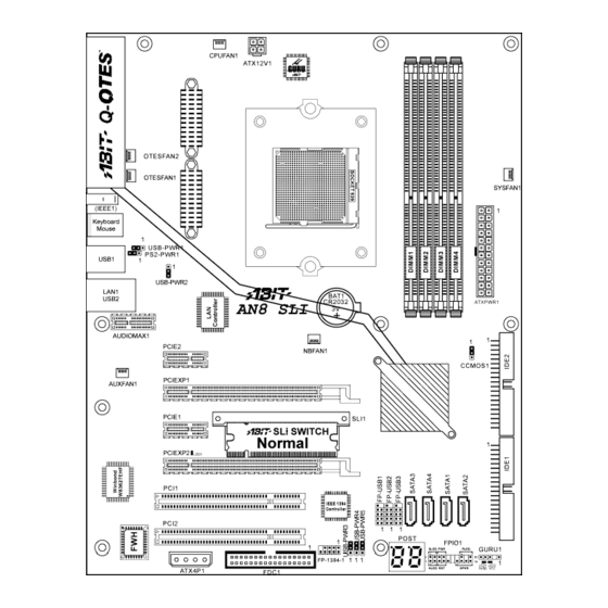
Layout Diagram (AN8 SLI) User’s Manual...
  • Page 8: Layout Diagram (An8 Ultra)

    Chapter 1 1-3. Layout Diagram (AN8 Ultra) AN8 Series...
  • Page 9: Layout Diagram (An8-3 Rd Eye/An8)

    Introduction 1-4. Layout Diagram (AN8-3 Eye/AN8) User’s Manual...
  • Page 10: Layout Diagram (An8 V2.0)

    Chapter 1 1-5. Layout Diagram (AN8 V2.0) AN8 Series...
  • Page 11: Layout Diagram (An8-V)

    Introduction 1-6. Layout Diagram (AN8-V) User’s Manual...
  • Page 12 Chapter 1 Chapter 1 AN8 Series AN8 Series...
  • Page 13: Chapter 2. Hardware Setup

    Hardware Setup Chapter 2. Hardware Setup Before the Installation: Turn off the power supply switch (fully turn off the +5V standby power), or disconnect the power cord before installing or unplugging any connectors or add-on cards. Failing to do so may cause the motherboard components or add-on cards to malfunction or damaged. 2-1.
  • Page 14: Install Cpu, Heatsink And Fan Assembly

    Chapter 2 2-2. Install CPU, Heatsink and Fan Assembly Please pay attention to the following notices before installing the CPU and heatsink/fan assembly. 1. Always use the processor with the Heatsink and Fan Assembly installed. 2. Do not touch the pins on the processor. 3.
  • Page 15 Hardware Setup 6. On the other side, push the retention clip straight down to lock into the plastic lug on the retention frame. 7. Turn the cam lever to lock into the retention frame. 8. Attach the four-pin power plug from the heatsink and fan assembly to the CPU FAN connector.
  • Page 16: Install System Memory

    Chapter 2 2-3. Install System Memory This motherboard provides four 184-pin DDR DIMM slots for Single/Dual Channel DDR 400/333/266 memory modules with memory expansion size up to 4GB. Table 2-1. Valid Memory Configurations Bank Memory Module Total Memory Bank 0, 1 (DIMM1) 256, 512MB, 1GB 256MB ~ 1GB Bank 2, 3 (DIMM2)
  • Page 17 [DIMM1]+[DIMM2], and slots [DIMM3]+[DIMM4]. AN8 Ultra/AN8 3 Eye/AN8/AN8 V2.0/AN8-V NOTE: This illustration is based on the model AN8 Ultra. All other models except for AN8 SLI share the same connector, header and jumper positions. AN8 SLI NOTE: Usually there is no hardware or BIOS setup requires after adding or removing memory modules, but you will have to clear the CMOS memory first if any memory module related problem occurs.
  • Page 18 Chapter 2 Power off the computer and unplug the AC power cord before installing or removing memory modules. 1. Locate the DIMM slot on the board. 2. Hold two edges of the DIMM module carefully, keep away touching connectors. 3. Align the notch key on the module with the rib on the slot.
  • Page 19: Install Two Graphics Cards With Nvidia Sli Technology (An8 Sli)

    NOTE: When PCIEXP2 slot functions as a PCIE x1 slot under Normal mode, insert the PCIE x1 card into the marked area of PCIEXP2 slot. This motherboard is factory pre-installed with an ABIT SLI switchboard. By the default “Normal” mode, this motherboard is set for one single graphics card operation. To operate two graphics cards on this motherboard, you will have to set the switchboard to “SLI”...
  • Page 20 Chapter 2 Please follow the instructions below to set the system to SLI mode and install your graphics cards. NOTE: Please handle the switchboard with caution. Watch out for the sharp edges. 3. Slightly push down the switchboard until the retention clip snap into places. Make sure the switchboard is completely inserted into the slot.
  • Page 21 Hardware Setup IMPORTANT: Please disable the following items in BIOS setup while running under SLI mode: All the “FanEQ controls” (CPU, NB, SYS, OTES1, OTES2 and AUX FanEQ Control) and “Cool ’n’ Quiet Technology”. The system may be unstable without doing so. Detail information about these items will be described in “Chapter 3.
  • Page 22: Connectors, Headers And Switches

    (Pin-11, 12, 23, and 24 should be left un-connected). AN8 Ultra/AN8 3 Eye/AN8/AN8 V2.0/AN8-V NOTE: This illustration is based on the model AN8 Ultra. All other models except for AN8 SLI share the same connector, header and jumper positions. AN8 Series...
  • Page 23 Hardware Setup 2-11 AN8 SLI Note: It is recommended to connect to a power with 350W, 20A +5VDC capacity at least for heavily loaded system, and a 2A +5VSB capacity at least for supporting wake-up features. The auxiliary 12V power connector [ATX4P1] provides an additional power source for devices added on PCI Express slots.
  • Page 24: Fan Power Connectors

    AUXFAN1: Auxiliary Fan Power Connector • NBFAN1: Chipset Fan Power Connector • OTESFAN1, OTESFAN2: OTES Fan Power Connector WARNING: These fan connectors are not jumpers. DO NOT place jumper caps on these connectors. AN8 Ultra/AN8 3 Eye/AN8/AN8 V2.0/AN8-V AN8 SLI AN8 Series...
  • Page 25: Cmos Memory Clearing Header

    Pin 2-3 shorted: Clear CMOS memory. WARNING: Turn the power off first (including the +5V standby power) before clearing the CMOS memory. Failing to do so may cause your system to work abnormally or malfunction. AN8 Ultra/AN8 3 Eye/AN8/AN8 V2.0/AN8-V AN8 SLI User’s Manual...
  • Page 26: Front Panel Switches & Indicators Headers

    LED to not light, but a wrong connection of the switches could cause system malfunction. AN8 Ultra/AN8 3 Eye/AN8/AN8 V2.0/AN8-V AN8 SLI • HLED (Pin 1, 3): Connects to the HDD LED cable of chassis front panel.
  • Page 27: Additional Usb Port Headers

    USB 2.0 specifications. AN8 Ultra/AN8 3 Eye/AN8/AN8 V2.0/AN8-V Pin Assignment Pin Assignment Data0 - Data1 - Data0 + Data1 + Ground Ground AN8 SLI Pin Assignment Pin Assignment Data0 - Data1 - Data0 + Data1 + Ground Ground User’s Manual...
  • Page 28: Additional Ieee1394 Port Headers

    This header provides one additional IEEE1394 port connection through an extension cable and bracket. AN8 Ultra/AN8 3 Eye/AN8/AN8 V2.0 Pin Assignment Pin Assignment TPA0 + TPA0 - TPB0 + TPB0 - +12V +12V AN8 SLI Pin Assignment Pin Assignment TPA0 + TPA0 - TPB0 + TPB0 - +12V +12V AN8 Series...
  • Page 29: Wake-Up Header

    (7). Wake-up Header These headers use a jumper cap to enable/disable the wake-up function. AN8 Ultra/AN8 3 Eye/AN8/AN8 V2.0/AN8-V AN8 SLI • PS2-PWR1: Pin 1-2 shorted: Disable wake-up function support at Keyboard/Mouse port. Pin 2-3 shorted (default): Enable wake-up function support at Keyboard/Mouse port.
  • Page 30 2-18 Chapter 2 • USB-PWR3: Pin 1-2 shorted: Disable wake-up function support at FP-USB1 port. Pin 2-3 shorted (default): Enable wake-up function support at FP-USB1 port. • USB-PWR4: Pin 1-2 shorted: Disable wake-up function support at FP-USB2 port. Pin 2-3 shorted (default): Enable wake-up function support at FP-USB2 port. •...
  • Page 31: Guru Clock Connection Header

    Hardware Setup 2-19 (8). GURU Clock Connection Header This header is reserved for connecting ABIT’s exclusive GURU Clock. AN8 Ultra/AN8 3 Eye/AN8/AN8 V2.0/AN8-V AN8 SLI User’s Manual...
  • Page 32: Floppy And Ide Disk Drive Connectors

    AN8 Ultra/AN8 3 Eye/AN8/AN8 V2.0/AN8-V AN8 SLI The FDC1 connector connects up to two floppy drives with a 34-wire, 2-connector floppy cable. Connect the single end at the longer length of ribbon cable to the FDC1 on the board, the two connectors on the other end to the floppy disk drives connector.
  • Page 33 Hardware Setup 2-21 Each of the IDE port connects up to two IDE drives at Ultra ATA/100 mode by one 40-pin, 80-conductor, and 3-connector Ultra ATA/66 ribbon cables. Connect the single end (blue connector) at the longer length of ribbon cable to the IDE port of this board, the other two ends (gray and black connector) at the shorter length of the ribbon cable to the connectors of your hard drives.
  • Page 34: Serial Ata Connectors

    2-22 Chapter 2 (10). Serial ATA Connectors These connectors are provided to attach one Serial ATA device at each channel via Serial ATA cable. AN8 Ultra/AN8 3 Eye/AN8/AN8 V2.0/AN8-V AN8 SLI AN8 Series...
  • Page 35: Status Indicators

    • LED1 (5VSB): This LED lights up when the power supply is connected with power source. • LED2 (VCC): This LED lights up when the system power is on. • LED3: This LED lights up when the system works on SLI mode. (AN8 SLI) AN8 Ultra/AN8 3 Eye/AN8/AN8 V2.0/AN8-V...
  • Page 36: Post Code Display

    POST Code in address 80h to find out where the problem lies. This LED device also displays the “POST” Code of AC2003, an “uGuru” chipset developed exclusively by ABIT computer. NOTE: The decimal point lights up when executing the AC2003 POST action.
  • Page 37: Pci Express X16 Slot

    Hardware Setup 2-25 (13). PCI Express x16 Slot This slot is used to attach the next generation of graphics architecture. AN8 Ultra/AN8 3 Eye/AN8/AN8 V2.0/AN8-V AN8 SLI User’s Manual...
  • Page 38: Pci Express X1 Slots

    These slots are used to attach the next generation of I/O architecture. AN8 Ultra/AN8 3 Eye/AN8/AN8 V2.0/AN8-V AN8 SLI (15). SLI Switchboard Slot (AN8 SLI) This slot and the pre-installed ABIT SLI Switch set the graphic mode to either Normal or SLI mode. AN8 SLI AN8 Series...
  • Page 39: Audiomax Slot

    The slot “AUDIOMAX1” provides the audio input/output connection at back panel through an audio daughter-card. NOTE: Install this daughter-card at slot “AUDIOMAX1”. AudioMAX 7.1 (AN8 SLI/AN8 Ultra) • SPDIF OUT: This connector provides an S/PDIF-Out connection through optical fiber to digital multimedia devices.
  • Page 40 2-28 Chapter 2 S/PDIF Connection: Note: Remove the rubber protection-caps before using this optical fiber cable. AN8 Series...
  • Page 41 Hardware Setup 2-29 • S/PDIF Output Connection: 1. Pull out the 3.5mm adapter at one end. Plug the rest of this end into the [SPDIF OUT] jack on the daughter-card. 2. Plug another end into the [S/PDIF In] (Digital In) jack on your digital multimedia device. User’s Manual...
  • Page 42 2-30 Chapter 2 • S/PDIF Input Connection: 1. Plug the end with 3.5mm adapter into the [Line-in/IN] jack on this daughter-card. (This jack is used for either optical or line input.) 2. Plug another end into the [S/PDIF Out] (Digital Out) jack on your digital multimedia device AN8 Series...
  • Page 43 Hardware Setup 2-31 • Line-in connection: 1. Plug one end of a standard 3.5mm audio stereo cable into the [Line-in/IN] jack on this daughter card. 2. Plug another end into the [Line-out] jack on your multimedia device User’s Manual...
  • Page 44 2-32 Chapter 2 Analog connection for 7.1 channel audio system: Please follow the below diagram to connect your sound system to the audio daughter card. AN8 Series...
  • Page 45 Hardware Setup 2-33 AudioMAX 5.1 (AN8 3 EYE/AN8/AN8 V2.0/AN8-V) • SPDIF IN: This connector provides an S/PDIF-In connection through optical fiber to digital multimedia devices. • SPDIF OUT: This connector provides an S/PDIF-Out connection through optical fiber to digital multimedia devices. •...
  • Page 46 2-34 Chapter 2 S/PDIF Connection: • S/PDIF Input Connection: 1. Remove the rubber protection-caps from both ends of the cable. 2. Plug one end of the cable into the [SPDIF IN] jack on this daughter-card. 3. Plug another end into the [Digital-Out] (SPDIF-Out) jack on your digital multimedia device. •...
  • Page 47 Hardware Setup 2-35 Analog connection for 5.1 channel audio system: Please follow the below diagram to connect your sound system to the audio daughter card. User’s Manual...
  • Page 48: Front Panel Audio Connection Header

    2-36 Chapter 2 (17). Front Panel Audio Connection Header This header provides the connection to audio connector at front panel. AN8 3 Eye/AN8/AN8 V2.0/AN8-V AN8 SLI/AN8 Ultra Pin Assignment Pin Assignment Audio Mic. Ground Audio Mic. Bias Speaker Out Right...
  • Page 49: Internal Audio Connectors

    Hardware Setup 2-37 (18). Internal Audio Connectors These connectors connect to the audio output of internal CD-ROM drive or add-on card. AN8 3 Eye/AN8/AN8 V2.0/AN8-V AN8 SLI/AN8 Ultra User’s Manual...
  • Page 50: Back Panel Connectors

    2-38 Chapter 2 (19). Back Panel Connectors AN8 SLI/AN8 Ultra/AN8 3 Eye/AN8/AN8 V2.0 AN8-V • Mouse: Connects to PS/2 mouse. • Keyboard: Connects to PS/2 keyboard. • IEEE1: Connects to devices of IEEE1394 protocol • LAN1: Connects to Local Area Network.
  • Page 51: Chapter 3. Bios Setup

    F6 : Save PROFILE to BIOS F7 :Load PROFILE from BIOS OC Guru & ABIT EQ NOTE: In order to increase system stability and performance, our engineering staffs are constantly improving the BIOS menu. The BIOS setup screens and descriptions illustrated in this manual are for your reference only and may not completely match what you see on your screen.
  • Page 52: Μguru ™ Utility

    There are two setup menus in this µGuru utility. You may switch between these two by clicking the left or right arrow key on keyboard: OC Guru: µGuru Utility V1.00 OC Guru ABIT EQ Brand Name: AMD Athlon(tm) 64 Processor 3400+ Item Help Frequency: 2200MHz CPU Operating Speed...
  • Page 53 BIOS Setup External Clock: This item selects the external clock frequency. Due to the specification limit of the CPU you installed, the speed you set over its standard bus speed is supported, but not guaranteed. Multiplier Factor: This item displays the multiplier factor for the CPU you installed. PCIE Clock This item selects the PCI Express frequency.
  • Page 54: Temperature Monitoring

    ↑↓:Move Enter:Select +/-/PU/PD:Value F8: On The Fly F10:Save ESC:Exit These items display the power cycle statistics for each element. ABIT EQ: Click right-arrow <→> key to switch from OC Guru setup menu to ABIT EQ setup menu: µGuru Utility V1 00 OC Guru...
  • Page 55 BIOS Setup µGuru Utility V1 00 OC Guru ABIT EQ Temperature Monitoring Reading Shutdow Shutdown Beep Beep Enab Temp. Enable Temp. (*)CPU Temperature 51 C/123 °F (*) 85 /185 F 75 C/167 F ° ° ° ° ° (*)SYS Temperature...
  • Page 56 Chapter 3 Voltage Monitoring: Click <Enter> key to enter its submenu: µGuru Utility V1.00 OC Guru ABIT EQ Voltage Monito ing Reading Shutdow Beep High Enab Enab Limit Limit (*)CPU Core Voltage 1.550V 1.89V 1.00V (*)DDR Voltage 2.70V 2.90V 2.10V (*)DDR VTT Voltage 1.35V...
  • Page 57: Fan Speed Monitoring

    BIOS Setup Fan Speed Monitoring: Click <Enter> key to enter its submenu: µGuru Utility V1.00 OC Guru ABIT EQ Fan Spe ed Monit Reading Shutdow Beep Low Limit Enab Enab (*)CPU FAN Speed 4020 RPM 1200 RPM (*)NB FAN Speed...
  • Page 58 Chapter 3 FanEQ1 Control: µGuru Utility V1.00 OC Guru ABIT EQ FanEQ1 Control CPU FanEQ Control Enabled Item Help -Reference Temperature Temper ature -Control Temperature High 65°C/149°F -Control Temperature Low 35°C/95°F -DC Fan Voltage High 12.0V -DC Fan Voltage Low 8.0V...
  • Page 59 BIOS Setup Reference Temperature: This item selects the reference point for taking temperature among the available options of CPU, SYS, and PWM Temperature, but there is only one “CPU Temperature” item to choose for the “CPU FanEQ Control”. Control Temperature High/Low: This item sets the high and low temperature limits desired for the fan speed control.
  • Page 60: Standard Cmos Features

    3-10 Chapter 3 3-2. Standard CMOS Features This section contains the basic configuration parameters of the BIOS. These parameters include date, hour, VGA card, FDD and HDD settings. Phoenix – Award WorkstationBIOS CMOS Setup Utility Standard CMOS Features Date (mm:dd:yy) Thu.
  • Page 61 BIOS Setup 3-11 Click <Enter> key to enter its submenu: Phoenix – Award WorkstationBIOS CMOS Setup Utility IDE Channel 1 Master IDE HDD Auto-Detection Press Enter Item Help IDE Channel 1 Master Auto Access Mode Auto Capacity 0 MB Cylinder Head Precomp Landing Zone...
  • Page 62 3-12 Chapter 3 Precomp: This item displays the number of cylinders at which to change the write timing. Landing Zone: This item displays the number of cylinders specified as the landing zone for the read/write heads. Sector: This item configures the number of sectors per track. Back to Standard CMOS Features Setup Menu: Drive A &...
  • Page 63: Advanced Bios Features

    BIOS Setup 3-13 3-3. Advanced BIOS Features Phoenix – Award WorkstationBIOS CMOS Setup Utility Advanced BIOS Features ► Removable Device Priority Press Enter Item Help ► Hard Disk Boot Priority Press Enter ► CD-ROM Boot Priority Press Enter First Boot Device Removable Second Boot Device CD-ROM...
  • Page 64 3-14 Chapter 3 Boot Up Floppy Seek: When the computer boots up, the BIOS detects if the system has a FDD or not. When this item is set to Enabled, if the BIOS detects no floppy drive, it will display a floppy disk drive error message. If this item is disabled, the BIOS will skip this test.
  • Page 65: Advanced Chipset Features

    BIOS Setup 3-15 3-4. Advanced Chipset Features Phoenix – Award WorkstationBIOS CMOS Setup Utility Advanced Chipset Features HT Frequency Item Help HT Width ↓16 ↑16 ► DRAM Configuration Press Enter SSE/SSE2 Instructions Enable System BIOS Cachable Disable ↑↓:Move Enter:Select +/-/PU/PD:Value F10:Save ESC:Exit F1:General Help F5: Previous Values F6: Fail-Safe Defaults F7: Optimized Defaults...
  • Page 66 3-16 Chapter 3 DRAM Timing Selectable: This item selects the DRAM timing mode. When set to “By SPD”, the BIOS will read the DRAM module SPD data and automatically set to the values stored in it. Leave this item to its default “Auto” setting. DRAM Clock: This item sets the DRAM clock of your DRAM module.
  • Page 67 BIOS Setup 3-17 Bank Interleaving: Three options are available: Disabled % 2 Way % 4 Way. The default setting is Disabled. Depending on your SDRAM module structure, the 4-Way setting can offer the best performance. If you choose the wrong setting, the computer system will not run in a stable manner. For detailed information on your SDRAM module, please ask your SDRAM module manufacturer.
  • Page 68: Integrated Peripherals

    3-18 Chapter 3 3-5. Integrated Peripherals Phoenix – Award WorkstationBIOS CMOS Setup Utility Integrated Peripherals ► Onchip PCI Device Press Enter Item Help ► IDE/RAID Function Press Enter USB Park Mode Disabled USB TD Reads ISO Queue USB Periodic Data Reads ISO Queue USB Asyn Data Reads Non-ISO Queue...
  • Page 69 BIOS Setup 3-19 USB Keyboard Support: This item allows you to select [Enabled] for using USB keyboard in DOS environment, or [Disabled] in OS environment. USB Mouse Support: This item allows you to select [Enabled] for using USB mouse in DOS environment, or [Disabled] in OS environment.
  • Page 70: Ide Function Setup

    3-20 Chapter 3 IDE Function Setup: Click <Enter> key to enter its submenu: Phoenix – Award WorkstationBIOS CMOS Setup Utility IDE F uction Se Onboard IDE-1 Controller Enabled Item Help Onboard IDE-2 Controller Enabled IDE DMA transfer access Enabled Serial-ATA 1 Enabled - SATA DMA transfer Enabled...
  • Page 71: Raid Config

    BIOS Setup 3-21 RAID Config: Click <Enter> key to enter its submenu: Phoenix – Award WorkstationBIOS CMOS Setup Utility RAID Config - RAID Enable Enabled Item Help X - IDE Primary Master RAID Disabled X - IDE Primary Slave RAID Disabled X - IDE Secondary Master RAID Disabled...
  • Page 72 3-22 Chapter 3 Init Display First: This item selects which display slot to be initialized first when the system boots. [PCI Slot]: When the system boots, it will first initialize PCI. [PCIEx]: When the system boots, it will first initialize PCIE. Onboard IEEE1394 Controller: This option enables or disables the IEEE 1394 controller.
  • Page 73: Power Management Setup

    BIOS Setup 3-23 3-6. Power Management Setup Phoenix – Award WorkstationBIOS CMOS Setup Utility Power Management Setup ACPI Suspend Type S3(Suspend-to-RAM Item Help - USB Resume from S3 Enabled Power Button Function Instant-Off Wake-Up by PME# of PCI Enabled Wake-Up by OnChip LAN Enabled Wake-Up by Alarm Disabled...
  • Page 74 3-24 Chapter 3 mode. Date (of Month) Alarm/ Time (hh:mm:ss) Alarm: You can set the Date (month) Alarm and Time Alarm (hh:mm:ss). Any event occurring will awaken a system that has powered down. Cool ’n’ Quiet Technology: This option enables or disables the AMD K8 cool and quiet function. NOTE: Please disable this item while running under SLI mode.
  • Page 75: Pnp/Pci Configurations

    BIOS Setup 3-25 3-7. PnP/PCI Configurations Phoenix – Award WorkstationBIOS CMOS Setup Utility PnP/PCI Configurations Resources Controlled By Auto(ESCD) Item Help x IRQ Resources Press Enter PCI/VGA Pallete Snoop Disbaled PIRQ_0 Use IRQ No. Auto PIRQ_1 Use IRQ No. Auto PIRQ_2 Use IRQ No.
  • Page 76 3-26 Chapter 3 Back to PnP/PCI Configurations Setup Menu: PCI/VGA Palette Snoop: This item determines whether the MPEG ISA/VESA VGA cards can work with PCI/VGA or not. [Disabled]: MPEG ISA/VESA VGA cards do not work with PCI/VGA. [Enabled]: MPEG ISA/VESA VGA cards work with PCI/VGA. PIRQ_0 Use IRQ No.
  • Page 77: Load Fail-Safe Defaults

    BIOS Setup 3-27 3-8. Load Fail-Safe Defaults This option loads the BIOS default values for the most stable, minimal-performance system operations. 3-9. Load Optimized Defaults This option loads the BIOS default values that are factory settings for optimal-performance system operations. 3-10.
  • Page 78 3-28 Chapter 3 AN8 Series...
  • Page 79: Appendix A. Install Nvidia Nforce Chipset Driver

    Install nVidia nForce Chipset Driver Appendix A. Install nVidia nForce Chipset Driver NOTE: Please install this NVIDIA nForce Chipset driver first after having installed the Windows operating system. The installation procedures and screen shots in this section are based on the Windows XP operating system.
  • Page 80 Appendix A 5. Click [Yes]. 9. Click [Yes]. 6. Click [Next]. 10. Choose [Yes, I want to restart my computer now.], and click [Finish] to complete setup. 7. Click [Next]. 8. Click [Next]. AN8 Series...
  • Page 81: Appendix B. Install Realtek Audio Driver

    Install Realtek Audio Driver Appendix B. Install Realtek Audio Driver The installation procedures and screen shots in this section are based on Windows XP operating system. For those of other OS, please follow its on-screen instruction. Insert the Driver & Utility CD into CD-ROM drive, it should execute the installation program automatically.
  • Page 82 Appendix B AN8 Series...
  • Page 83: Appendix C. Install Usb 2.0 Driver

    Install USB 2.0 Driver Appendix C. Install USB 2.0 Driver NOTE: The installation for USB 2.0 driver for Windows XP or Windows 2000 is currently available by updating the latest Service Pack from Microsoft’s web site. User’s Manual...
  • Page 84 Appendix C AN8 Series...
  • Page 85: Appendix D. Install Amd64 Processor Driver

    Install AMD64 Processor Driver Appendix D. Install AMD64 Processor Driver The installation procedures and screen shots in this section are based on Windows XP operating system. For those of other OS, please follow its on-screen instruction. Insert the Driver & Utility CD into CD-ROM drive, it should execute the installation program automatically.
  • Page 86 Appendix D 6. Click [Next]. 9. After the system restarted, open the “Power Options” from the control panel and choose the power scheme “Minimal Power Management” to enable Cool ‘n’ Quiet. NOTE: For Windows 2000 or ME system, an AMD Cool ‘n’ Quiet tab will appear under “Power Options”...
  • Page 87: Appendix E. Install Abit Μguru Utility

    CD to enter the installation menu. After entering the installation menu, move your cursor to the [ABIT Utility] tab. Click [ABIT µGuru]. The following screen appears. 3. Click [Finish] to complete setup. 1. Click [Next].
  • Page 88 Appendix E AN8 Series...
  • Page 89: Appendix F. An8 Nvraid Floppy Disk

    CD to enter the installation menu. After entering the installation menu, move your curser to [ABIT Utility] tab. Click [AN8 NVRaid Floppy Disk]. The following screen appears. 1. Insert one blank floppy disk to the selected floppy drive and click [Build].
  • Page 90 Appendix F AN8 Series...
  • Page 91: Appendix G. Post Code Definition

    POST Code Definition Appendix G. POST Code Definition AWARD POST Code Definition: POST Description (hex) Test CMOS R/W functionality Early chipset initialization: -Disable shadow RAM -Disable L2 cache (socket 7 or below) -Program basic chipset registers Detect memory -Auto-detection of DRAM size, type and ECC -Auto-detection of L2 cache (socket 7 or below) Expand compressed BIOS code to DRAM Call chipset hook to copy BIOS back to E000 &...
  • Page 92 Appendix G Load keyboard matrix (notebook platform) HPM initialization (notebook platform) 1. Check validity of RTC value: e.g. a value of 5Ah is an invalid value for RTC minute. 2. Load CMOS settings into BIOS stack. If CMOS checksum fails, use default value instead.
  • Page 93 POST Code Definition Display number of processors (multi-processor platform) Display PnP logo Early ISA PnP initialization -Assign CSN to every ISA PnP device Initialize the combined Trend Anti-Virus code (Optional Feature) Show message for entering AWDFLASH.EXE from FDD (optional) 1. Initialize Init_Onboard_Super_IO 2.
  • Page 94 Appendix G 1. Invoke all ISA adapter ROMs 2. Invoke all PCI ROMs (except VGA) 1. Enable/Disable Parity Check according to CMOS setup 2. APM Initialization Clear noise of IRQs Read HDD boot sector information for Trend Anti-Virus code 1. Enable L2 cache 2.
  • Page 95 POST Code Definition AC2003 POST Code Definition: POST Description (hex) Power On Sequence 8.1. Start power on sequence 8.2. Enable ATX power supply 8.3. ATX power supply ready 8.4. DDR voltage ready 8.5. Setup PWM for CPU core voltage 8.6. Assert PWM for CPU core voltage 8.7.
  • Page 96 Appendix G AN8 Series...
  • Page 97: Appendix H. Troubleshooting (Need Assistance

    Troubleshooting (Need Assistance?) Appendix H. Troubleshooting (Need Assistance?) Q & A: Q: Do I need to clear the CMOS before I use a new motherboard to assemble my new computer system? A: Yes, we highly recommend that you clear the CMOS before installing a new motherboard. Please move the CMOS jumper from its default 1-2 position to 2-3 for a few seconds, and then back.
  • Page 98 Appendix H Q: How can I get a quick response to my request for technical support? A: Be sure to follow the guidelines as stated in the “Technical Support Form” section of this manual. If you have a problem during operation, in order to help our technical support personnel quickly determine the problem with your motherboard and give you the answers you need, eliminate any peripheral that is not related to the problem, and indicate it on the form.
  • Page 99 To fill in this “Technical Support Form”, refer to the step-by-step instructions given below: . MODEL: Note the model number given in your user’s manual. Example: AN8 SLI, AN8 Ultra, AN8-3 Eye, AN8, AN8 V2.0, AN8-V . Motherboard model number (REV): Note the motherboard model number labeled on the motherboard as “REV:*.**”.
  • Page 100: Technical Support Form

    Appendix H ) Technical Support Form * Phone Number: ! Company Name: " Contact Person: # Fax Number: + E-mail Address: Model BIOS ID # Motherboard Model No. DRIVER REV OS/Application Hardware Name Brand Specifications IDE1 IDE2 IDE1 CD-ROM-Drive IDE2 System Memory ADD-ON CARD Problem Description:...
  • Page 101: Appendix I. How To Get Technical Support

    Also please make sure you have the latest drivers from your peripheral card makers! 3. Check the ABIT Technical Terms Guide and FAQ on our website. We are trying to expand and make the FAQs more helpful and information rich. Let us know if you have any suggestions.
  • Page 102 They should have reasonable return or refund policies. How they serve you is also a good reference for your next purchase. 6. Contacting ABIT. If you feel that you need to contact ABIT directly you can send email to the ABIT technical support department. First, please contact the support team for the branch office closest to you.
  • Page 103 Unit 3, 24-26 Boulton Road, Stevenage, Herts SG1 4QX, UK Tel: 44-1438-228888 Fax: 44-1438-226333 E-mail: sales@abitcomputer.co.uk Germany and Benelux (Belgium, AMOR Computer B.V. (ABIT's European Office) Netherlands, Luxembourg), Jan van Riebeeckweg 15, 5928LG, Venlo, France, Italy, Spain, Portugal, The Netherlands Greece, Denmark, Norway, Tel: 31-77-3204428...
  • Page 104 Please contact the reseller from whom you bought the product. You should be able to get RMA service there. 8. Reporting Compatibility Problems to ABIT. Because of tremendous number of email messages we receive every day, we are forced to give greater weight to certain types of messages than to others.

This manual is also suitable for:

An8An8 v2.0An8-v

Table of Contents