Table of Contents
Advertisement
Quick Links
Advertisement
Table of Contents

Related Manuals for VIA Technologies VAB-800


Summary of Contents for VIA Technologies VAB-800
- Page 1 USER MANUAL VAB-800 Pico-ITX Freescale Cortex-A8 board 1.02-01042013-141500...
-
Page 2: Regulatory Compliance
The information and product specifications within this document are subject to change at any time, without notice and without obligation to notify any person of such change. VIA Technologies, Inc. reserves the right the make changes to the products described in this manual at any time without prior notice. -
Page 3: Safety Precautions
Battery Recycling and Disposal Only use the appropriate battery specified for this product. Do not re-use, recharge, or reheat an old battery. Do not attempt to force open the battery. Do not discard used batteries with regular trash. Discard used batteries according to local regulations. Safety Precautions Always read the safety instructions carefully. - Page 4 800 User Manual User Manual User Manual User Manual Box Contents and Ordering Information VAB- - - - 800 1 x VAB-800 1 x DC jack power cable 1 x Audio cable 1 x CAN BUS/USB cable 1 x COM cable...
-
Page 5: Table Of Contents
VAB- - - - 800 800 User Manual User Manual User Manual User Manual Table of Contents 1. 1. 1. 1. Product Overview Product Overview ........ Product Overview Product Overview ........................................................................ 1 1 1 1 1.1. - Page 6 47 47 A.1. Starter Kit Assembly ..................47 A.2. VAB-800-A Specifications ................49 A.3. VAB-800-A Layout....................50 A.4. VAB-800-A Pinouts and Jumpers..............51 Appendix B. Mating Connector Vendor Lists Appendix B. Mating Connector Vendor Lists Appendix B. Mating Connector Vendor Lists Appendix B.
- Page 7 User Manual User Manual Lists of Figures Figure 1: Layout diagram of the VAB-800 mainboard (top and bottom view) ... 5 Figure 2: Mounting holes and dimensions of the VAB-800........7 Figure 3: Height distribution of the VAB-800 mainboard ........8 Figure 4: External I/O ports.....................
- Page 8 User Manual User Manual Lists of Tables Table 1: Layout diagram description table of the VAB-800 mainboard ....6 Table 2: Layout diagram description table of external I/O ports ......9 Table 3: Fast Ethernet port pinout ................10 Table 4: Fast Ethernet LED color definition .............. 10 Table 5: USB 2.0 port pinout..................
-
Page 9: Product Overview Product Overview
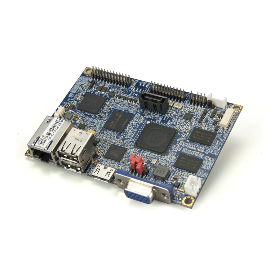
Based on the ultra compact Pico-ITX form factor, measuring 10 cm x 7.2 cm, the VIA VAB-800 is the first VIA Pico-ITX board to feature an ARM SoC. With the choice of either an 800MHz or 1GHz Freescale Cortex-A8 ARM SoC, the... -
Page 10: Key Features
VAB- - - - 800 800 User Manual User Manual User Manual User Manual 1.1. Key Features Supports integrated graphics processing (GPU) for 3D/2D graphics acceleration and dual displays Supports two single-channel 18/24-bit LVDS connectors Supports four USB ports (two as pin headers) and one USB device port Supports two COM ports Supports mini-HDMI and VGA ports Small form factor and low power design... -
Page 11: Product Specifications
VAB- - - - 800 800 User Manual User Manual User Manual User Manual 1.2. Product Specifications Processor Processor Processor Processor Freescale Cortex-A8 Single-Core i.MX537 @800MHz (Optional for i.MX535 @1.0GHz) Flash Flash Flash Flash eMMC Flash (up to 64GB) ... - Page 12 VAB- - - - 800 800 User Manual User Manual User Manual User Manual 1 X JTAG connector 1 X Boot flash select pin header 1 X miscellaneous pin header for 2 USB2.0 ports, 1 USB device port, 2 CAN bus ports, ...
-
Page 13: Layout Diagram
VAB- - - - 800 800 User Manual User Manual User Manual User Manual 1.3. Layout Diagram Figure Figure 1 1 1 1 : Layout diagram of the : Layout diagram of the VAB VAB- - - - 800 800 mainboard mainboard (top (top and bottom and bottom view) - Page 14 VAB- - - - 800 800 User Manual User Manual User Manual User Manual Item Item Description Description Item Item Description Description i.MX537 J4: Boot Select HDMI transmitter eMMC Flash J8: RTC Battery Connector MC34708 PMIC J10: DIO, Touch and I2C combination pin header SATA connector J2: CAN Bus Jumper J9: USB, USB device, CAN, RST and PWNON combination pin header...
-
Page 15: Product Dimensions
VAB- - - - 800 800 User Manual User Manual User Manual User Manual 1.4. Product Dimensions Figure Figure Figure Figure 2 2 2 2 : : : : Mounting holes and dimensions of Mounting holes and dimensions of Mounting holes and dimensions of the Mounting holes and dimensions of the VAB VAB- - - - 800... -
Page 16: Height Distribution
VAB- - - - 800 800 User Manual User Manual User Manual User Manual 1.5. Height Distribution Figure Figure Figure Figure 3 3 3 3 : Height distribution of the : Height distribution of the : Height distribution of the : Height distribution of the VAB VAB- - - - 800 800 mainboard... -
Page 17: I/O Interface
2. 2. 2. 2. I/O Interface I/O Interface I/O Interface I/O Interface The VAB-800 has a wide selection of interfaces. It includes a selection of frequently used ports as part of the external I/O coastline. 2.1. External I/O Ports Figure... -
Page 18: Lan Port: Fast Ethernet
VAB- - - - 800 800 User Manual User Manual User Manual User Manual 2.1.1. LAN port: Fast Ethernet The integrated 8-pin Fast Ethernet port is using an 8 Position 8 Contact (8P8C) receptacle connector (commonly referred to as RJ45). The Fast Ethernet ports are controlled by VIA Fast Ethernet controller. -
Page 19: Usb 2.0 Port
User Manual 2.1.2. USB 2.0 Port The VAB-800 mainboard provides two USB 2.0 ports, Each USB port gives complete Plug and Play and hot swap capability for external devices. The USB interface complies with USB UHCI, Rev. 2.0. The pinout of the typical USB 2.0 port is shown below. -
Page 20: Mini Hdmi ® Port
VAB- - - - 800 800 User Manual User Manual User Manual User Manual ® 2.1.3. Mini HDMI Port ® ® The integrated 19-pin HDMI port uses an HDMI Type C connector as defined in the HDMI ® specification. The HDMI ®... -
Page 21: Vga Port
VAB- - - - 800 800 User Manual User Manual User Manual User Manual 2.1.4. VGA Port The 15-pin VGA port uses a female DE-15 connector. The VGA port is for connecting to analog displays. The pinout of the VGA port is shown below. Figure Figure Figure... -
Page 22: Onboard Connectors
VAB- - - - 800 800 User Manual User Manual User Manual User Manual 2.2. Onboard Connectors 2.2.1. LVDS1 & LVDS2 Connectors The mainboard has two 24-pin LVDS panel connectors on the bottom side. The onboard LVDS panel connectors allow to connect the panel’s LVDS cable to support the single-channel 18-bit/24-bit display. - Page 23 VAB- - - - 800 800 User Manual User Manual User Manual User Manual Signal Signal Signal Signal Signal Signal Signal Signal LVDS0_TX0_N 12C2_SCL LVDS0_TX0_P 12C2_SDA PVDD1 (3.3V-default; 5V-optional) LVDS0_TX1_N- PVDD1 (3.3V-default; 5V-optional) LVDS0_TX1_P IVDD1 (5V) IVDD1 (5V) LVDS0_TX2_N- DISP0_CONTRAST LVDS0_TX2_P DISP0_RD LCD0_BLT_EN...
-
Page 24: Sata Connector
VAB- - - - 800 800 User Manual User Manual User Manual User Manual 2.2.2. SATA Connector The SATA connector onboard can support up to 1.5 Gb/s transfer speeds. The SATA connector has a 7th pin that can provide +5V power to a SATA Disk- on-Module (DOM). - Page 25 VAB- - - - 800 800 User Manual User Manual User Manual User Manual SRXP_0 GND/+5V Table Table 10 10: SATA connector pinouts : SATA connector pinouts Table Table 10 10 : SATA connector pinouts : SATA connector pinouts Note: Note: Note: Note:...
-
Page 26: Usb/Usb Device/Can/Rst/Pwnon Combination Pin Header
VAB- - - - 800 800 User Manual User Manual User Manual User Manual 2.2.3. USB/USB device/CAN/RST/PWNON Combination Pin Header The mainboard includes one USB, USB device, CAN, RST and PWNON combination pin header block labeled as “J9”. The combination pin header is for connecting USB, USB device, CAN, RST and PWNON devices. - Page 27 VAB- - - - 800 800 User Manual User Manual User Manual User Manual PWNON1 USB_OTG_DP GLBRST USB_OTG_DN EXT_USB5V P_LED Table Table 11 11: : : : US USB B B B / / / / USB USB device device/ / / / CAN CAN/ / / / RST RST/ / / / PWNON PWNON combination...
-
Page 28: Dio + Touch + I2C Combination Pin Header
VAB- - - - 800 800 User Manual User Manual User Manual User Manual 2.2.4. DIO + Touch + I2C Combination Pin Header The mainboard includes one DIO, 4-wire resistive touch and I2C combination pin header block labeled as “J10”. The pinout of the pin header is shown below. -
Page 29: F_Audio Pin Header
VAB- - - - 800 800 User Manual User Manual User Manual User Manual 2.2.5. F_Audio Pin Header The mainboard has a pin header for Line-out, Line-in and MIC-in. The pin header is labeled as “AUDIO”. The pinout of the pin header is shown below. Figure Figure 13 13: : : : F_Audio pin header... -
Page 30: External Sata Power Connector
VAB- - - - 800 800 User Manual User Manual User Manual User Manual 2.2.6. External SATA Power Connector The mainboard provides one built-in SATA power connector. This connector is required to power SATA hard drive. The SATA power connector is labeled as “PWR1”. -
Page 31: Sata Dom Power Select
VAB- - - - 800 800 User Manual User Manual User Manual User Manual 2.2.7. SATA DOM Power Select The SATA connectors can be used to support Disk-on-Module (DOM) flash drives. When the jumpers are set, +5V will be delivered to the 7 pin of the SATA connectors. -
Page 32: Com1 Connector
2.2.8. COM1 Connector The mainboard includes one onboard COM connector on the top side of VAB-800. The onboard COM connector labeled as “COM1” is used to attach additional COM port that support RS-232 standard with DCE (data communication Equipment) type. The pinout of COM connector is as shown below. -
Page 33: Com2 Connector
2.2.9. COM2 Connector The mainboard includes one onboard COM connector on the bottom side of VAB-800. The onboard COM connector labeled as “COM2” is used to attach additional COM port that support RS-232 standard. COM2 connector is used for debugging only. The pinout of COM connector is as shown below. -
Page 34: Rtc Battery Connector
VAB- - - - 800 800 User Manual User Manual User Manual User Manual 2.2.10. RTC Battery Connector The mainboard is equipped with onboard RTC battery connector used for connecting the external cable battery that provides power to the 32.768KHz crystal oscillator for Real Time Clock (RTC). -
Page 35: Dc-In Power Connector
VAB- - - - 800 800 User Manual User Manual User Manual User Manual 2.2.11. DC-In Power Connector The mainboard supports +5V DC-In power connector to provide addition power to the rest of the system. The 2-pin power connector is used to connect the DC-In power jack. -
Page 36: J_Tag Connector
VAB- - - - 800 800 User Manual User Manual User Manual User Manual 2.2.12. J_TAG Connector The J_TAG connector provides a set of JTAG signals that allow JTAG debugging equipment to be used. The connector is labeled as “JTAG”. The pinout of the connector is shown below. -
Page 37: Boot Select
VAB- - - - 800 800 User Manual User Manual User Manual User Manual 2.2.13. Boot Select The Boots Select jumper labeled as J4 is to specify the boot device. Figure Figure 21 21: : : : Boot Select Boot Select jumper jumper Figure Figure... -
Page 38: Can Bus
VAB- - - - 800 800 User Manual User Manual User Manual User Manual 2.2.14. CAN BUS The CAN BUS jumper labeled as J2 is used to enable/disable CAN BUS termination device. Figure Figure 22 22: : : : CAN BUS jumper CAN BUS jumper Figure Figure... -
Page 39: Hardware Installation Hardware Installation
Hardware Installation 3.1. Installing into a Chassis The VAB-800 can be fitted into any chassis that has the mounting holes compatible with the standard Pico-ITX mounting hole locations. Additionally, the chassis must meet the minimum height requirements for specified areas of the mainboard. -
Page 40: Suggested Minimum Chassis Height
VAB- - - - 800 800 User Manual User Manual User Manual User Manual 3.1.2. Suggested minimum chassis height The figure below shows the suggested minimum height requirements for the internal space of the chassis. It is not necessary for the internal ceiling to be evenly flat. -
Page 41: Suggested Keepout Areas
VAB- - - - 800 800 User Manual User Manual User Manual User Manual 3.1.3. Suggested keepout areas The figure below shows the areas of the mainboard that is highly suggested to leave unobstructed. Figure Figure 25 25: Suggested keepout areas : Suggested keepout areas Figure Figure... -
Page 42: Connection Of Cables
User Manual User Manual User Manual 3.2. Connection of Cables VAB-800 is equipped with 4 cables, including DC-in X 1, COM X 1, Audio X 1, USB/CAN X 1. The figure below shows the connection of these cables. DC-in USB/CAN... -
Page 43: Making Ubuntu Demo Image
4. 4. 4. 4. Making Ubuntu Demo Image Making Ubuntu Demo Image Making Ubuntu Demo Image Making Ubuntu Demo Image This section describes how to evaluate the VAB-800 with Ubuntu image downloaded from Freescale official web site. Note: Note: Note: Note: 1. - Page 44 VAB- - - - 800 800 User Manual User Manual User Manual User Manual 3. Go to “Featured Embedded Software and Tools”. Click the “i.MX Softward and Development Tools”. Go to “i.MX Development Boards and Systems by Device”. Click the “i.MX53”...
- Page 45 VAB- - - - 800 800 User Manual User Manual User Manual User Manual Click “Downloads”. There are development tools and prebuilt images shown here. You can select Run-time Software to expand all items. Download MX53_QSB_UBUNTU_SD_DEMO_IMAGE http://www.freescale.com/webapp/sps/site/prod_summary.jsp?code=IMX53QSB&fpsp=1 http://www.freescale.com/webapp/sps/site/prod_summary.jsp?code=IMX53QSB&fpsp=1 http://www.freescale.com/webapp/sps/site/prod_summary.jsp?code=IMX53QSB&fpsp=1 http://www.freescale.com/webapp/sps/site/prod_summary.jsp?code=IMX53QSB&fpsp=1 &tab=Design_Tools_Tab# &tab=Design_Tools_Tab# &tab=Design_Tools_Tab#...
-
Page 46: Making Demo Image Into Micro Sd
Follow the steps to make bootable Micro SD storage card. 4.3. Replace U-boot/Kernel/Modules of VAB-800 User has to replace u-boot, kernel and modules binary files which built from VAB-800 BSP on the Micro SD storage card. These files can be found from EVK folder. Getting u-boot, kernel and modules. - Page 47 ./modules.tar.bz2 /mnt/mountpoint/lib user@user:~/EVK$ cd /mnt/mountpoint/lib user@user:/mnt/mountpoint/lib$ sudo tar jxvf modules.tar.bz2 Put modification files in root file system The configuration files should be modified for VAB-800. User can use files “vab-800_rootfs_patch.tar.bz2” in EVK folder. Unzip vab-800_rootfs_patch.tar.bz2 ■ user@user:~/EVK$ sudo tar jxvf vab-800_rootfs_patch.tar.bz2 User will get the following files as shown below: User runs the script “vab-800.sh”...
- Page 48 User Manual User Manual User Manual Boot from Micro SD storage card (on VAB-800) Attach COM cable to VAB-800 COM2, and connect to your computer ■ To modify parameters in u-boot ■ To setup or modify u-boot parameters in u-boot:...
- Page 49 User has to save the parameters when completing the settings. VAB-800 U-Boot > saveenv VAB-800 U-Boot > boot Finally, user should get the parameter in u-boot after modifying, type command in u-boot. In the example: the display is VGA and boot from Micro SD card.
- Page 50 VAB- - - - 800 800 User Manual User Manual User Manual User Manual XGA di1_primary vga bootcmd_obds=ext2load mmc 0:1 0x70800000 /unit_tests/obds.bin; go 70800000 nfsroot=/tftpboot/rootfs lcd=video=mxcdi0fb:RGB24,SEIKO-WVGA di0_primary lvds=video=mxcdi0fb:RGB666,XGA di0_primary ldb=di0 lvds1=video=mxcdi0fb:RGB24,480C60 di0_primary ldb=di0 vga=off lvds2=video=mxcdi1fb:RGB24,480C60 di1_primary ldb=di1 vga=off bootcmd=run bootcmd_mmc; bootm ${loadaddr} bootfile=uImage bootargs=console=ttymxc1,115200 gpu_nommu setenv bootargs console=ttymxc1,115200 video=mxcdi0fb:RGB24,1920x1080M@60 hdmi...
-
Page 51: Setting U-Boot
For example: To set 1680 x 1050 resolution, change VGA-XGA with VGA- WSXGA+: setenv vga 'setenv bootargs console=ttymxc1,115200 video=mxcdi1fb:GBR24,VGA-WSXGA+ di1_primary vga' There are four modes to be set in VAB-800: VGA-WSXGA+ : 1680x1050p-60 VGA-SXGA : 1280x1024p-60 VGA-XGA : 1024x768p-60 VGA-SVGA : 800x600p-60... - Page 52 To set LVDS port setenv lvds1 ‘video=mxcdi0fb:RGB24,480C60 di0_primary ldb=di0 vga=off’ setenv lvds2 ‘video=mxcdi1fb:RGB24,480C60 di1_primary ldb=di1 vga=off’ VAB-800 support AUO 7” 800x480 LVDS panel in default. Setting storage devices [ [ [ [ Mic Micro SD ro SD storage storage card...
- Page 53 VAB- - - - 800 800 User Manual User Manual User Manual User Manual [eMMC] [eMMC] [eMMC] [eMMC] setenv bootargs_emmc ‘setenv bootargs ${bootargs} root=/dev/mmcblk0p2 rootwait rw’ setenv bootcmd_emmc ‘run bootargs_base bootargs_emmc;fatload mmc 1 0x70800000 uImage;bootm’ Setting booting storage devices Here, user can set the boot device as either Micro SD or eMMC. Set boot device as Micro SD: setenv bootcmd ‘run bootcmd_mmc;...
-
Page 54: Making Demo Image To Emmc (Optional)
VAB- - - - 800 800 User Manual User Manual User Manual User Manual 4.5. Making demo image to eMMC (optional) This section will guide user to copy images to eMMC for evaluation. However, it is a must to finish first the section 4.2~4.3 before applying this section. To make a demo image compression file, follow the steps below: Getting u-boot, and kernel image. -
Page 55: Appendix A. Starter Kit Appendix A. Starter Kit
1 x COM cable To install the VAB-800-A to the VAB-800 mainboard, align and attach the board-to-board connectors (J3, J1 & J2) on the bottom of VAB-800-A with the pin headers (F_audio, J9 & J10 respectively) on the top of VAB-800 mainboard. - Page 56 VAB- - - - 800 800 User Manual User Manual User Manual User Manual The figure below shows the connection of panel. Figure Figure Figure Figure 29 29 29 29: : : : Connection of panel Connection of panel Connection of panel Connection of panel...
-
Page 57: Vab-800-A Specifications
VAB- - - - 800 800 User Manual User Manual User Manual User Manual A.2. VAB-800-A Specifications Onboard I/O Onboard I/O Onboard I/O Onboard I/O 1 x I²C pin header 1 x DPIO pin header (4 Ins and 4 OUTS) ... -
Page 58: Vab-800-A Layout
VAB- - - - 800 800 User Manual User Manual User Manual User Manual A.3. VAB-800-A Layout CAN D-sub connector Reset button Audio I/O connector Power button USBOTG USB2.0 4-wire connector J_I²C3 Figure Figure 30 30: : : : VAB... -
Page 59: Vab-800-A Pinouts And Jumpers
VAB- - - - 800 800 User Manual User Manual User Manual User Manual A.4. VAB-800-A Pinouts and Jumpers Signal Signal Signal Signal Signal Signal Signal Signal GPO_10 GPI_2 GPO_11 GPI_16 GPO_12 GPI_18 GPO_13 GPI_19 J_I²C3 Signal Signal Signal Signal... -
Page 61: Appendix B. Mating Connector Vendor Lists Appendix B. Mating Connector Vendor Lists
Appendix B. Mating Connector Mating Connector Mating Connector Mating Connector Vendor Lists Vendor Lists Vendor Lists Vendor Lists The following table listed the mating connector vendor lists of VAB-800 mainboard. Connectors Connectors Vendor & Connectors Connectors Vendor & Vendor & P/N Vendor &...
Need help?
Do you have a question about the VAB-800 and is the answer not in the manual?
Questions and answers