
Related Manuals for Agilent Technologies N4010A


Summary of Contents for Agilent Technologies N4010A
- Page 1 Getting Started Guide Wireless Connectivity Test Set N4010A Manufacturing Part Number: N4010-90086 Printed in Malaysia November 2013 © Copyright Agilent Technologies, Inc. 2006, 2009, 2013...
- Page 2 Agilent shall not be liable for errors or for incidental or consequential damages in connection with the furnishing, use, or performance of this document or any information contained herein.
-
Page 3: Legal Information
Certification Agilent Technologies certifies that this product met its published specifications at the time of shipment from the factory. Agilent Technologies further certifies that its calibration measurements are traceable to the United States National Institute of Standards and Technology, to the extent allowed by the Institute’s calibration facility, and to the calibration facilities of other International Standards Organization members. -
Page 4: Safety Notices
Test Set. Failure to comply with these precautions or with specific warnings elsewhere in this manual violates safety standards of design, manufacture, and intended use of the Test Set. Agilent Technologies assumes no liability for the customer’s failure to comply with these requirements. - Page 5 REMOVE POWER and do not use the product until safe operation can be verified by service-trained personnel. If necessary, return the product to a Agilent Sales and Service Office for service and repair to ensure the safety features are maintained.
- Page 6 Acknowledgements Bluetooth® and the Bluetooth Logo® are trademarks owned by Bluetooth SIG, Inc., U.S.A. and licensed to Agilent Technologies, Inc. MATLAB® is a U.S. registered trademark of The Math Works, Inc. Microsoft® is a U.S. registered trademark of Microsoft Corporation. Windows®...
-
Page 7: Table Of Contents
Agilent Sales and Service Offices ........ - Page 8 Contents viii...
-
Page 9: Getting Started
Getting Started Chapter 1... -
Page 10: Welcome
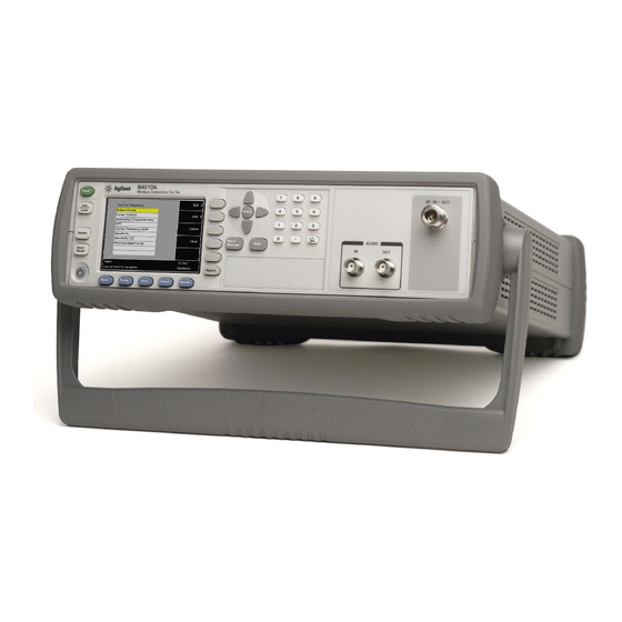
Getting Started Welcome Welcome Welcome to the Agilent Technologies N4010A Wireless Connectivity Test Set’s Getting Started Guide. Use this guide with the N4010A, equipped with any option, to help you: • Inspect the Test Set. • Adjust the carrying handle. -
Page 11: Interfacing With The N4010A
PC and the PC connected to the N4010A Test Set. Full Front Panel operation of the N4010A Test Set is limited to system functions and to Bluetooth 1.1 and 1.2 RF Testing (option 101). Rear Panel operation via SCPI is similarly limited. - Page 12 Getting Started Interfacing with the N4010A Table 1-1 Test Set Control Differences Between Bluetooth and WLAN Function Bluetooth Test Bluetooth EDR WLAN Test Test Control of via LMP commands DUT control from test Test Device from Test Set and EUT...
-
Page 13: Initial Inspection
If there is mechanical damage, notify the nearest Agilent Technologies office. Keep the damaged shipping materials (if any) for inspection by the carrier and an Agilent representative. If required, you can find a list of “Agilent Sales and Service Offices” on page 48. -
Page 14: Adjusting The Carrying Handle
Getting Started Adjusting the Carrying Handle Adjusting the Carrying Handle Adjust the carrying handle to carry the Test Set or view the display. The carrying handle can be locked into three different positions. Pull the handle outwards, rotate it to the required position and release it into one of the three locks. -
Page 15: Turning The Test Set On
Getting Started Turning the Test Set On Turning the Test Set On CAUTION The Test Set has an autoranging power supply. Ensure the supply voltage is within the range 100 V to 240 V and 50 Hz to 60 Hz. 1. - Page 16 Getting Started Turning the Test Set On 3. Turn the test set on and confirm the background LED is green. 4. The test set automatically steps through a self test routine. After this routine you should see the following display... 5.
-
Page 17: System Information
Getting Started Turning the Test Set On System Information To verify your configuration, press the key, an example is shown in Figure System 1-2. Figure 1-2 Typical System Configuration Screen Chapter 1... - Page 18 Check the Test Set fuse. (see below) Fails self test(s) If there are any self-test failures the test set is defective. Contact your nearest Agilent Service Center (Refer to Agilent Sales and Service Offices on page 48). In line fuse Spare fuse...
-
Page 19: Minimum Pc Requirements
CD-ROM Drive or Internet connection for application download. • Internet connection for license redemption. (if required) In addition, to be able to run the N4010A CD-ROM and connect using the remote interfaces, your PC must also have the following software components installed: •... -
Page 20: Installing The Measurement Software, Applications, And Help
Typically, a PC re-start is required following the N4010A WLAN Test Suite installation. If you are installing both WLAN and Bluetooth components, we recommend that you install the N4010A WLAN Test Suite first, and install the Bluetooth components following the PC re-start. -
Page 21: Making Your First Measurements
Making Your First Measurements Chapter 2... -
Page 22: Selecting The Application Mode
The purpose of this guide is to allow you to confirm the Test Set functions. NOTE For further detail read the help provided on the N4010A CD-ROM. • To perform a confidence check for Bluetooth local control only, refer to “Running a Confidence Check on the Front Panel (Bluetooth)”... -
Page 23: Running A Confidence Check On The Front Panel (Bluetooth)
Making Your First Measurements Running a Confidence Check on the Front Panel (Bluetooth) Running a Confidence Check on the Front Panel (Bluetooth) To operate Bluetooth testing from the Front Panel, your N4010A must be configured with: • Option 101. Refer to the N4010A web page at www.agilent.com/find/N4010A for firmware updates. - Page 24 Making Your First Measurements Running a Confidence Check on the Front Panel (Bluetooth) Figure 2-2 Test Set RFIO Connections 3. Press the Config key. Figure 2-3 Typical Configure Link Screen when ACL is Selected 4. Use the keys to highlight and select an ACL Link as shown in Arrow Select Figure 2-3.
- Page 25 Making Your First Measurements Running a Confidence Check on the Front Panel (Bluetooth) Figure 2-4 Typical Inquiry Results Screen 8. Ensure your device is highlighted in yellow, use the arrow keys if necessary, as shown in Figure 2-4. 9. Press the Select &...
-
Page 26: Connecting Usb, Gpib Or Lan
For more detailed information on configurating the remote interface connectivity, refer to the Agilent Technologies USB, LAN or GPIB Interfaces Connectivity Guide. You can access the Connectivity Guide via the Agilent IO Libraries Control icon. Alternatively, you can access the Connectivity Guide via the internet at www.agilent.com/find/connectivity. - Page 27 In the prompt select No, not this time, Click Next. Click Next to install the software automatically. By installing the Agilent I/O Libraries software, you also installed low-level drivers. This means you do not need to insert the drivers CD when the wizard requests it.
- Page 28 3. Run the Connection Expert program. It can be opened by double clicking the icon in the task bar notification area or from the windows task bar, Start>All Programs>Agilent IO Libraries Suite>Agilent Connection Expert. In the Connection Expert program, click on Refresh All.
- Page 29 Making Your First Measurements Connecting USB, GPIB or LAN Figure 2-6 Typical Connection Expert Screen showing GPIB Connection 4. The Test Set is displayed under the GPIB list in the centre of the screen. 5. You have successfully completed Step 2 of the 3 Step process. To complete the confidence check for •...
- Page 30 Making Your First Measurements Connecting USB, GPIB or LAN Connecting by LAN The Test Set has two LAN operating modes. • Dynamic Host Configuration Protocol (DHCP) • Static IP (Manual Mode) Configuring the Test Set The IP Address, Subnet Mask, and Default Gateway, can be changed manually or remotely.
- Page 31 Making Your First Measurements Connecting USB, GPIB or LAN DHCP Mode In DHCP mode the IP Address, Subnet Mask and Default Gateway values are obtained automatically from the server. When you use DHCP you cannot configure the IP Address, Subnet Mask or Default Gateway values from the front panel. 1.
- Page 32 1. Run the Connection Expert program. It can be opened by double clicking the icon in windows notification area or from the windows task bar, Start>All Programs>Agilent IO Libraries Suite>Agilent Connection Expert. 2. Right click on the LAN Interface section. Shown in Figure 2-8.
- Page 33 Making Your First Measurements Connecting USB, GPIB or LAN 6. In the pop up screen, shown in Figure 2-9, select the IP Address link. 7. Enter the IP address which is displayed on the Test Set. 8. Click on Test Connection. 9.
- Page 34 Making Your First Measurements Connecting USB, GPIB or LAN Static IP In static mode you must set up the IP Address, Subnet Mask, and Default Gateway that is compatible with your network infrastructure. If it is not correctly setup, the Test Set is not be visible on your network.
-
Page 35: Running A Scpi Confidence Check
N4010A CD-ROM Installation Guide, you can proceed directly to Step 2. Step 1. Install the Agilent I/O Libraries Suite software by following the instructions on the N4010A CD-ROM or: 1. Insert the Agilent Automation-Ready into your CD drive and install using the on-screen instructions. - Page 36 Running a SCPI Confidence Check Step 3. Sending SCPI commands 1. In the Agilent Connection Expert program, click on Refresh All. 2. Select the Test Set from the Instrument I/O on this PC panel as shown in Figure 2-11. If you do not see your Test Set then expand the appropriate connection type by clicking on the + symbol.
-
Page 37: Running A Wlan Confidence Check
Making Your First Measurements Running a WLAN Confidence Check Running a WLAN Confidence Check To operate a WLAN Confidence Check, your N4010A Test Set must be configured with: • Firmware revision A.02.00.11 or later • Option 102 or Option 103 •... - Page 38 Making Your First Measurements Running a WLAN Confidence Check If you have previously installed the N4010A Wireless LAN Test Suite, the Agilent I/O Libraries Suite software and the Microsoft .NET Framework service pack 1, using the procedure described in the N4010A CD-ROM Installation Guide, you can proceed directly to Step 2.
- Page 39 Step 3. Rename the Test Set in Connection Wizard. 1. In the Agilent Connection Expert, Click on Refresh All as shown in Figure 2-13. 2. From the Instrument I/O on this PC panel, select your Test Set listing with a right click.
- Page 40 Making Your First Measurements Running a WLAN Confidence Check 4. Click on the Demo tab. 5. Click on Run Demo. 6. The display shows a loopback waveform similar to Figure 2-14. Figure 2-14 Test Harness Demo Screen Congratulations!! The WLAN Confidence Check is complete. Chapter 2...
-
Page 41: Running The Graphical Measurement Application (Gma) N4017A
N4010A Wireless Connectivity Test Set. The GMA makes it possible to fully configure the Test Set remotely. To operate with the Bluetooth GMA, your N4010A Test Set must be configured with: •... - Page 42 Making Your First Measurements Running the Graphical Measurement Application (GMA) N4017A. If you have previously installed the Agilent N4017A Bluetooth GMA, the Agilent I/O Libraries Suite software and the Microsoft .NET Framework service pack 1, using the procedure described in the N4010A CD-ROM Installation Guide, you can proceed directly to Step 2.
- Page 43 Test Set RFIO Connections 3. Minimize the Connection Expert program. 4. Run the GMA program from the windows task bar using, Start>All Programs>Agilent N4017A Bluetooth GMA>N4017A Bluetooth GMA or double click the desktop icon if created during the installation. Chapter 2...
- Page 44 Making Your First Measurements Running the Graphical Measurement Application (GMA) N4017A. 5. Use the Instrument Selector to locate your Test Set from the appropriate connection you have made. If you do not see your Test Set then expand the appropriate connection type by clicking on the + symbol. Figure 2-17 Typical GMA Instrument Selector Screen 6.
- Page 45 Making Your First Measurements Running the Graphical Measurement Application (GMA) N4017A. Figure 2-18 Typical Connection Control Screen 10. In the Inquiry section, click on Start. 11. The EUT’s numbers appear in a few seconds. 12. Click on the EUT’s numbers to highlight it. 13.
- Page 46 Making Your First Measurements Running the Graphical Measurement Application (GMA) N4017A. 15. In the Control menu, click Run Single. 16. The test parameters are populated with PASS or FAIL information, an example is shown in Figure 2-19. Figure 2-19 Typical Results Screen in the GMA NOTE It is not important whether the tests pass or fail.
-
Page 47: Rack Mounting The Test Set
If the total power dissipated in the cabinet is greater than 800 Watts, then forced convection must be used. Rack Mounting Using the Option N4010A-AX4 rack mount kit 1. Remove the carrying handle. 2. Remove the front and rear rubber bumpers. - Page 48 Making Your First Measurements Rack Mounting the Test Set 3. Fit the Rack Mount Flanges. (Parts available separately: 5063-9241). Ready for installation. Chapter 2...
-
Page 49: Regulatory Information
Regulatory Information Chapter 3... -
Page 50: General Specifications
Regulatory Information General Specifications General Specifications Environmental Operating C to +55 Temperature Storage C to +70 Temperature: Humidity: 15 to 95% Altitude: 3000m (9,840 ft.) EMC: Meets EN55011: 1991 (Group 1, Class A), and EN50082-1:1992. Physical Specifications Weight (Net): 6.82 Kg (Bluetooth option) Dimensions: 105H x 370W x 390D mm nominal Power Requirements... - Page 51 For continued protection against fire hazard, replace the line fuse only with the same type and line rating (250V, T 3.15A, 20mm Time-Lag fuse with Low breaking capacity, Agilent Part Number 2110-0638). The use of other fuses or materials is prohibited. Always disconnect the Test Set from the mains supply before attempting to replace the fuse.
-
Page 52: Compliance And Markings
Regulatory Information Compliance and Markings Compliance and Markings Electromagnetic Compatibility (EMC) This product conforms with the protection requirements of European Council Directive 89/336/EEC for Electromagnetic Compatibility (EMC). The conformity assessment requirements have been met using the technical Construction file route to compliance, using EMC test specifications EN 55011:1991 (Group 1, Class A) and EN 50082-1:1992. - Page 53 Directive Annex I, this product is classed as a “Monitoring and Control instrumentation” product. Do not dispose in domestic household waste. To return unwanted products, contact your local Agilent office or see www.agilent.com/environmental/product/ for more information. This is a USB symbol, and indicates a Universal Serial Bus port or ports.
-
Page 54: Regulatory Information
Regulatory Information Regulatory Information Regulatory Information Sound Emission Herstellerbescheinigung Diese Information steht im Zusammenhang mit den Anforderungen der Maschinenlarminformationsverordnung vom 18 Januar 1991. • Sound Pressure LpA < 70dB. • Am Arbeitsplatz. • Normaler Betrieb. Nach DIN 45635 T. 19 (Typprufung). Manufacturers Declaration This statement is provided to comply with the requirements of the German Sound DIN 45635 T. -
Page 55: Responsibilities Of The Customer
• Access to and use of all information and facilities determined necessary by Agilent to service and/or maintain the products. (Insofar as these items may contain proprietary or classified information, the customer shall assume full responsibility for safeguarding and protection from wrongful use.) •... -
Page 56: Agilent Sales And Service Offices
Agilent Sales and Service Offices In any correspondence or telephone conversations, refer to the Test Set by its model number and full serial number. With this information, the Agilent representative can quickly determine whether your unit is still within its warranty period.