Table of Contents
Advertisement
Model No. 831.15402.2
Serial No.
Write the serial number in the
space above for reference.
Serial Number Decal (under seat)
• Assembly
• Adjustments
• Troubleshooting
• Part List and Drawing
CAUTION
Read all precautions and instruc-
tions in this manual before using
this equipment. Save this manu-
al for future reference.
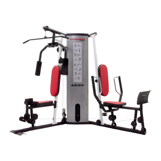
WEIGHT SYSTEM EXERCISER
Sears, Roebuck and Co., Hoffman Estates, IL 60179
User's Manual
Patent Pending
Advertisement
Table of Contents

Related Manuals for Weider Pro 4250


Summary of Contents for Weider Pro 4250
- Page 1 Model No. 831.15402.2 Serial No. Write the serial number in the space above for reference. WEIGHT SYSTEM EXERCISER User’s Manual Serial Number Decal (under seat) • Assembly • Adjustments • Troubleshooting • Part List and Drawing Patent Pending CAUTION Read all precautions and instruc- tions in this manual before using this equipment.
-
Page 2: Table Of Contents
TABLE OF CONTENTS WARNING DECAL PLACEMENT ............. 2 IMPORTANT PRECAUTIONS . -
Page 3: Important Precautions
IMPORTANT PRECAUTIONS WARNING: To reduce the risk of serious injury, read the following important precautions before using the weight system. 1. Read all instructions in this manual and all 10. The weight system is designed to be used warnings on the weight system before using only with the included weight. -
Page 4: Before You Begin
BEFORE YOU BEGIN Thank you for selecting the versatile WEIDER ® reading this manual, call 1-800-4-MY-HOME ® 4250 weight system. The weight system offers an (1-800-469-4663). To help us assist you, please note impressive array of weight stations designed to devel- the product model number and serial number before op every major muscle group of the body. -
Page 5: Assembly
ASSEMBLY Make sure you have the following tools: Make Assembly Easier for Yourself • Two adjustable wrenches Everything in this manual is designed to • One standard screwdriver ensure that the weight system can be assem- bled successfully by anyone. Before begin- •... - Page 6 Frame Assembly Before beginning assembly, make sure you understand the information in the box on page 5. See the PART IDENTIFICATION CHART in the center of this manual for help identifying small parts. Insert four M8 x 72mm Carriage Bolts (69) up through the Right Base (1).
- Page 7 5. See drawing A. Attach the Right Upright (2) to the Right Base (1) with the two indicated M8 x 72mm Carriage Bolts (69) and two M8 Nylon Locknuts (91). Do not tighten the Locknuts yet. See drawing B. Attach the Left Upright (26) to the Left Base (25) with the two indicated M8 x 72mm Carriage Bolts (69) and two M8 Nylon Locknuts (91).
- Page 8 7. Attach the Left Seat Frame (27) to the Left Base (25) with the two indicated M8 x 72mm Carriage Bolts (69) and two M8 Nylon Locknuts (91). Do not tighten the Locknuts yet. Attach the Left Seat Frame (27) to the Left Upright (26) with two M8 x 77mm Bolts (82), two M8 Washers (98), and two M8 Nylon Locknuts (91).
- Page 9 9. Slide two Weight Bumpers (45) onto the Weight Guides (44). Slide the eight Weights (55), with the pin holes on the indicated side, onto the Weight Guides. Grease Press the Weight Tube Bumper (46) into the Weight Tube (47). Insert the Weight Tube into the stack of Weights (55).
- Page 10 12. Attach the Left Top Frame (36) to the Right Top Frame (5) with four M8 x 77mm Bolts (82), two M8 Washers (98), a Support Plate (31), and four M8 Nylon Locknuts (91). Do not tighten the Locknuts yet. 13.
- Page 11 16. Attach the Leg Bumper (59) to the Right Seat Frame (3) with an M4 x 16mm Self-tapping Screw (89) and an M4 Washer (96). Grease Grease an M10 x 72mm Bolt (60). Attach the Leg Lever (4) to the Right Seat Frame (3) with the Bolt and an M10 Nylon Locknut (90).
-
Page 12: Cable Assembly
19. Attach a Press Arm (30) to the Press Frame (29) with two M8 x 66mm Bolt (86) and two M8 Nylon Locknuts (91). Repeat this step with the other Press Arm (30). 20. Grease an M10 x 106mm Bolt (72). Attach the Leg Press Frame (28) to the Left Base (25) with the Bolt and an M10 Nylon Locknut (90). - Page 13 23. Wrap the Press Cable (109) around a 90mm Pulley (63). Attach the Pulley, two Half Finger Guards (66), a Cable Trap (68), and an M10 Washer (99) to the Left Seat Frame (27) with an M10 x 103mm Bolt (22) and an M10 Nylon Locknut (90).
- Page 14 27. Wrap the Press Cable (109) around a “V”-pulley (62). Attach the “V”-pulley, two Half Finger Guards (66), a Large Cable Trap (111), and an M10 Washer (99) inside the bracket on the Left Upright (26) with an M10 x 65mm Bolt (77) and an M10 Nylon Locknut (90).
- Page 15 31. Attach the end of the Press Cable (109) to a “U”- bracket (50) with an M8 Washer (98) and an M8 Nylon Locknut (91). Note: Do not completely tighten the Locknut; it should be tightened so that only two threads of the Cable show past the Locknut, as shown in the inset drawing.
- Page 16 36. Grease an M8 x 20mm Shoulder Bolt (39). Attach the Butterfly Cable (106) to the Right Butterfly Grease Arm (7) with the Bolt and an M8 Nylon Locknut (91). Make sure the flat edge of the Cable is against the Butterfly Arm. Flat Edge 37.
- Page 17 41. Route the Weight Cable (110) over a 90mm Pulley (63) and down through the Right Top Frame (5). Attach the Pulley inside the Top Frame with an M10 x 80mm Bolt (75), two M10 Washers (99), two M10 x 19mm Spacers (102), and an M10 Nylon Locknut (90).
- Page 18 46. Locate the Ab Cable (107). Route the small ball on the Cable through the Leg Lever (4) and the Right Seat Frame (3). Make sure the Cable is over the rod in the Seat Frame. Attach a 90mm Pulley (63) inside the Leg Lever (4), over the Ab Cable (107), with an M10 x Large 65mm Bolt (77), two M10 Washers (99), two M10...
- Page 19 50. Wrap the Ab Cable (107) under a 90mm Pulley 90 66 (63). Attach the Pulley, a Cable Trap (68), and two Half Finger Guards (66) to the Right Base (1) with an M10 x 48mm Bolt (64) and an M10 Nylon Locknut (90).
-
Page 20: Seat Assembly
55. Wrap the Ab Cable (107) over a 90mm Pulley (63). Attach the Pulley and the two Quarter Finger Guards (105) to the Right Upright (2) with an M10 x 106mm Bolt (72), an M10 Washer (99), and an M10 Nylon Locknut (90). Make sure that the rod is inserted through both Finger Guards and is over the Cable. - Page 21 59. Attach the Butterfly Backrest (9) to the Right Upright (2) with four M6 x 16mm Screws (88). 60. Press the two Shroud Covers (11) onto the Shroud (10). Attach the Shroud to the Right Top Frame (5) and the Center Base (52) with four M6 x 22mm Bolts (87), four M6 Washers (97), and four M6 Nylon Locknuts (92).
-
Page 22: Adjustments
61. Attach the Lock Plate (21) to the Right Seat Frame (3) with an M8 x 67mm Shoulder Bolt (41), an M8 Washer (98), and an M8 Nylon Locknut (91). Do not overtighten the Locknut; the Lock Plate must be able to pivot easily. Attach the Leg Pin (24) to the Right Seat Frame (3) with an M4 x 16mm Self-tapping Screw (89). -
Page 23: Adjustments
ADJUSTMENTS This section explains how to adjust the weight system. See the EXERCISE GUIDELINES on page 29 for important information about how to get the most benefit from your exercise program. Also, see the accompanying exercise guide to see the correct form for each exercise. Make sure all parts are properly tightened each time the weight system is used. - Page 24 ADJUSTING THE BACKREST To adjust the position of the Press Backrest (113), disengaging the Knob (43) from the Left Upright (26) and move the Backrest to the desired position. Reengage the Knob into the Left Upright and the Backrest Frame (53). Make sure the Knob is fully tightened.
-
Page 25: Weight Resistance Chart
WEIGHT RESISTANCE CHART The chart below shows the approximate weight resistance at each exercise station. “Top” refers to the 6 lb. top weight. The other numbers refer to the 12.5 lb. weight plates. Weight resistance shown for the butterfly arm sta- tion is for each arm. -
Page 26: Cable Diagrams
CABLE DIAGRAMS The cable diagrams below show the proper routing of the Butterfly Cable (106), the Ab Cable (107), the Short Cable (108), the Press Cable (109), and the Weight Cable (110). Use the diagrams to make sure that the cables and the cable traps have been assembled correctly. - Page 27 Weight Cable (110) Length: 12 feet 1 inch Press Cable (109) Length: 22 feet 6 inches...
-
Page 28: Tightening The Cables
MAINTENANCE Make sure all parts are properly tightened each time the weight system is used. Replace any worn parts imme- diately. The weight system can be cleaned with a damp cloth and a mild, non-abrasive detergent. Do not use solvents. TIGHTENING THE CABLES Woven cable, the type of cable used on the weight system, can stretch slightly when it is first used. -
Page 29: Exercise Guidelines
EXERCISE GUIDELINES THE FOUR BASIC TYPES OF WORKOUTS PERSONALIZING YOUR EXERCISE PROGRAM Muscle Building Determining the exact length of time for each workout, To increase the size and strength of your muscles, as well as the number of repetitions or sets completed, push them close to their maximum capacity. -
Page 30: Muscle Chart
Rest for a short period of time after each set. The slowly as you stretch and do not bounce. Ease into ideal resting periods are: each stretch gradually and go only as far as you can • Rest for three minutes after each set for a muscle without strain. - Page 31 EXERCISE WEIGHT SETS REPS MONDAY Date: AEROBIC EXERCISE TUESDAY Date: EXERCISE WEIGHT SETS REPS WEDNESDAY Date: THURSDAY AEROBIC EXERCISE Date: EXERCISE WEIGHT SETS REPS FRIDAY Date: Make photocopies of this page for scheduling and recording your workouts.
- Page 32 PART IDENTIFICATION CHART—Model No. 831.15402.2 See the drawings below to identify small parts used in assembly. The number in parentheses by each drawing is the key number of the part, from the PART LIST in the center of this manual. Note: Some small parts may have been pre-attached.
- Page 33 M6 x 35mm Screw (78) M8 x 72mm Carriage Bolt (69) M8 x 20mm Shoulder Bolt (39) M10 x 75mm Bolt (76) M6 x 22mm Bolt (87) M8 x 77mm Bolt (82) M6 x 16mm Screw (88) M10 x 80mm Bolt (75) M4 x 16mm Self-tapping Screw (89) M10 x 85mm Bolt (74) M8 x 86mm Shoulder Bolt (37)
-
Page 34: Right Top Frame
PART LIST—Model No. 831.15402.2 R0905A Key No. Qty. Description Key No. Qty. Description Right Base M10 x 72mm Bolt Right Upright Double “U”-bracket Right Seat Frame “V”-pulley Leg Lever 90mm Pulley Right Top Frame M10 x 48mm Bolt Left Butterfly Arm Lock Pin Right Butterfly Arm Half Finger Guard... - Page 35 EXPLODED DRAWING A—Model No. 831.15402.2 R0905A 98 98 89 96...
- Page 36 EXPLODED DRAWING B—Model No. 831.15402.2 R0905A 63 66...
-
Page 37: Full 90-Day Warranty
FULL 90-DAY WARRANTY For 90 days from the date of purchase, if failure occurs due to defect in material or workmanship in this WEIGHT SYSTEM EXERCISER, contact the nearest Sears Service Center throughout the United States and Sears will repair or replace the WEIGHT SYSTEM EXERCISER, free of charge. This warranty does not apply when the WEIGHT SYSTEM EXERCISER is used commercially or for rental purposes.
Need help?
Do you have a question about the Pro 4250 and is the answer not in the manual?
Questions and answers