Weider 9150 User Manual
Uk manual
Hide thumbs
Also See for 9150:
- Manuale d'istruzioni (31 pages) ,
- Manual del usuario (31 pages) ,
- Manuel de l'utilisateur (30 pages)
Advertisement
Model No.WEEVSY49220
Serial No.
(Write the serial number in the
space above for reference.)
Serial Number Decal (under seat)
QUESTIONS?
As a manufacturer, we are
committed to providing com-
plete customer satisfaction. If
you have questions, or if there
are missing parts, please call:
08457 089 009
Or write:
ICON Health & Fitness, Ltd.
Unit 4
Revie Road Industrial Estate
Revie Road
Beeston
Leeds, LS118JG
UK
email: csuk@iconeurope.com
CAUTION
Read all precautions and instruc-
tions in this manual before using
this equipment. Save this manual
for future reference.
USER'S MANUAL
Visit our website at
www.iconeurope.com
Advertisement
Table of Contents

Related Manuals for Weider 9150


Summary of Contents for Weider 9150
- Page 1 USER'S MANUAL Model No.WEEVSY49220 Serial No. (Write the serial number in the space above for reference.) Serial Number Decal (under seat) QUESTIONS? As a manufacturer, we are committed to providing com- plete customer satisfaction. If you have questions, or if there are missing parts, please call: 08457 089 009 Or write:...
-
Page 2: Table Of Contents
Note: A PART IDENTIFICATION CHART and a PART LIST/EXPLODED DRAWING are attached in the centre of this manual. Remove the PART IDENTIFICATION CHART and PART LIST/EXPLODED DRAWING before begin- ning assembly. WEIDER is a registered trademark of ICON Health & Fitness, Inc. -
Page 3: Important Precautions
IMPORTANT PRECAUTIONS WARNING: To reduce the risk of serious injury, read the following important precautions before using the weight system. 1. Read all instructions in this manual and in 11. Make sure that the cables remain on the pul- the accompanying literature before using the leys at all times. -
Page 4: Before You Begin
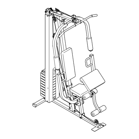
(see the front tem, the WEIDER ® 9150 will help you to achieve the cover of this manual). specific results you want. Before reading further, please review the drawing... -
Page 5: Assembly
ASSEMBLY Make sure you have the following tools: Make Assembly Easier for Yourself • Two adjustable spanners Everything in this manual is designed to • One standard screwdriver ensure that the weight system can be assem- bled successfully by anyone. Before begin- •... - Page 6 FRAME ASSEMBLY Small Holes Before beginning assembly, make sure you have read and understood the information on page 5. This introduction will save you more time than it takes to read it. Press a 40mm x 60mm Inner Cap (27) into the end of the Base (4).
- Page 7 3. Insert the two Weight Guides (62) into the indicat- ed holes in the Base (4) and the Stabiliser (5). Be sure that the Weight Guides are oriented with Hole the holes in the positions shown. Attach the Weight Guides to the Base and the Stabiliser with two M10 x 78mm Bolts (14), two 17.5mm Spacers (77), two M10 Washers (9), and two M10 Nylon Locknuts (21).
- Page 8 5. Press four 40mm x 60mm Inner Caps (27) into the ends of the Top Frame (55). 6. Hold the Top Frame (55) on top of the Front Upright (42) between the Weight Guides (62). Attach the Top Frame to the Front Upright with two M10 x 60mm Bolts (7), the Support Plate (71), and two M10 Nylon Locknuts (21).
- Page 9 9. Press a 50mm Square Inner Cap (44) into the end of the Right Butterfly Arm (48). Press a Sleeve (89) into the Right Butterfly Arm. Wet the lower end of the Right Butterfly Arm (48) with soapy water. Slide a Large Foam Pad (45) onto the Right Butterfly Arm.
- Page 10 12. Wrap the High Cable (23) around a “V”-Pulley (6). Attach the Pulley and a Long Cable Trap (50) to the bracket on the Top Frame (55) with an M10 x 60mm Bolt (7) and an M10 Nylon Locknut (21). Be sure the Cable Trap is oriented to hold the Cable in the groove of the Pulley.
- Page 11 16. Route the High Cable (23) up through the Top Frame (55), around the 115mm Pulley (74), and back down through the Top Frame. Attach the Pulley inside the Top Frame with an M10 x 75mm Bolt (76), two 17.5mm Spacers (77), two M10 Washers (9), and an M10 Nylon Locknut (21).
- Page 12 20. Wrap the Low Cable (69) around a 90mm Pulley (15). Attach the Pulley and a pair of Pulley Covers (40) to the second set of holes from the bottom of the two Pulley Plates (58) with an M10 x 52mm Bolt (12) and an M10 Nylon Locknut (21).
- Page 13 24. Wrap the Low Cable (69) around a 90mm Pulley (15). Attach the Pulley and a pair of Pulley Covers (40) to the Press Frame (17) with the M10 x 135mm Bolt (75) used in step 22, and an M10 Nylon Locknut (21).
- Page 14 27. Attach the Backrest (41) to the Front Upright (42) with two M6 x 73mm Bolts (43) and two M6 Washers (78). 28. Press a 38mm Square Inner Cap (32) into the end of the Seat Frame (36). Attach the Bumper (67) to the Seat Frame (36) with the M5 x 20mm Self-tapping Screw (80).
- Page 15 31. Attach the Seat Frame (36) to the Front Upright (42) with the M10 x 80mm Carriage Bolt (11) and the Seat Knob (49). 32. Attach the Curl Pad (24) to the Curl Post (35) with two M6 x 16mm Screws (18). 33.
-
Page 16: Adjustments
ADJUSTMENTS This section explains how to adjust the weight system. See the EXERCISE GUIDELINES on page 21 for impor- tant information about how to get the most benefit from your exercise program. Also, refer to the accompanying exercise guide to see the correct form for several exercises. Make sure all parts are properly tightened each time the weight system is used. - Page 17 ATTACHING THE SEAT FRAME To attach the Seat Frame (36) to the Front Upright (42), slide one of the three slots in the bracket on the Seat Frame onto the pin on the Front Upright. Note: Slot The Seat Frame can be adjusted to three heights using the different slots in the bracket.
-
Page 18: Weight Resistance Chart
WEIGHT RESISTANCE CHART The chart below shows the approximate weight resistance at each exercise station. “Top” refers to the 6-lb. top weight. The other numbers refer to the 12.5 lb. weight plates. Weight resistance shown for the butterfly arm sta- tion is for each butterfly arm. -
Page 19: Troubleshooting And Maintenance
TROUBLESHOOTING AND MAINTENANCE Make sure all parts are properly tightened each time the weight system is used. Replace any worn parts immedi- ately. The weight system can be cleaned using a damp cloth and mild non-abrasive detergent. Do not use sol- vents. -
Page 20: Cable Diagrams
CABLE DIAGRAMS The cable diagrams below show the proper routing of the High Cable (23) and the Low Cable (69). Use the dia- grams to make sure that the cables and the cable traps have been assembled correctly. If the cables have not been correctly routed, the weight system will not function properly and damage may occur. -
Page 21: Exercise Guidelines
EXERCISE GUIDELINES THE FOUR BASIC TYPES OF WORKOUTS PERSONALISING YOUR EXERCISE PROGRAM Muscle Building Determining the exact length of time for each workout, To increase the size and strength of your muscles, as well as the number of repetitions or sets completed, push them close to their maximum capacity. - Page 22 Rest for a short period of time after each set. The slowly as you stretch and do not bounce. Ease into ideal resting periods are: each stretch gradually and go only as far as you can • Rest for three minutes after each set for a muscle without strain.
- Page 23 EXERCISE WEIGHT SETS REPS MONDAY Date: AEROBIC EXERCISE TUESDAY Date: EXERCISE WEIGHT SETS REPS WEDNESDAY Date: THURSDAY AEROBIC EXERCISE Date: EXERCISE WEIGHT SETS REPS FRIDAY Date: Make photocopies of this page for scheduling and recording your workouts.
-
Page 24: Ordering Replacement Parts
Fax: 0 (044) 113 387 7125 Please provide the following information when ordering replacement parts: • the MODEL NUMBER of the product (WEEVSY49220) • the NAME of the product (WEIDER ® 9150 weight system) • the SERIAL NUMBER of the product (see the front cover of this manual) •... -
Page 25: Arm Assembly
This chart is provided to help you identify the small parts used in assembly. The number in parenthesis below each part refers to the key number of the part from the PART LIST in the centre of this manual. Important: Some parts may have been pre-assembled for shipping purposes. - Page 26 40mm x 60mm Inner Cap (27) 50mm Square Inner Cap (44) 38mm Square Inner Cap (32) 40mm x 60mm Outer Cap (73) 19mm Round Inner Cap (34) 25mm Round Inner Cap (10) 25mm Square Inner Cap (86) 25mm Round Cover Cap (62) 25mm Retainer (68)
- Page 27 PART IDENTIFICATION CHART —Model No. WEEVSY49220 R0702A...
- Page 28 REMOVE THIS PART LIST/EXPLODED DRAWING FROM THE MANUAL. SAVE THIS PART LIST/EXPLODED DRAWING FOR FUTURE REFERENCE...
- Page 29 PART LIST—Model No. WEEVSY49220 R0702A Key No. Qty. Description Key No. Qty. Description M10 x 55mm Carriage Bolt Right Butterfly Arm M6 Nylon Locknut Seat Knob M8 Nylon Locknut Long Cable Trap Base Curl Knob Stabiliser Chain “V”-Pulley Cable Clip M10 x 60mm Bolt Lat Bar M10 x 80mm Bolt...
- Page 30 EXPLODED DRAWING—Model No. WEEVSY49220 R0702A...
Need help?
Do you have a question about the 9150 and is the answer not in the manual?
Questions and answers