Advertisement
Quick Links
ORDERING REPLACEMENT PARTS
To order replacement parts, write or call:
Consumer Products Distribution
M40 Distribution Park
Loxley Road
Wellesbourne
Warwick
CV35 9JY
Tel:
0345-089009
Fax:
Country Code: (44) 0789-470798
1. The MODEL NUMBER of the product (WESY95450).
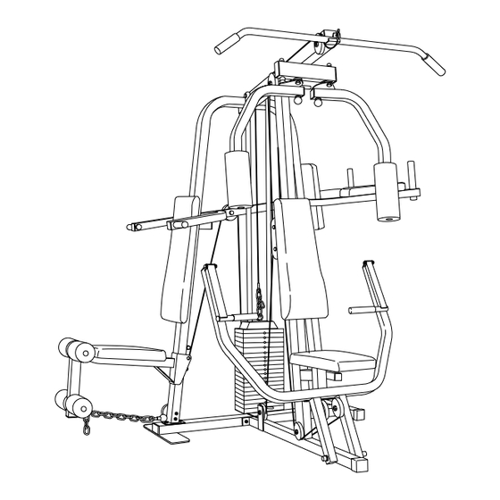
2. The NAME of the product (WEIDER
®
PRO 9545 Home Gym System).
3. The SERIAL NUMBER of the product (see the front cover of this manual).
4. The KEY NUMBER and DESCRIPTION of the part(s) (see the EXPLODED DRAWING and PART LIST
attached to the center of this manual).
Part No. 129382 R0496A © 1996 ICON Health & Fitness, Inc.
Model No. WESY95450
Serial No.
Write the serial number in the space
above for reference.
Serial Number Decal (under seat)
QUESTIONS?
As a manufacturer, we are com-
mitted to providing complete
customer satisfaction. If you have
questions, or find that there are
missing or damaged parts, we
will guarantee you complete sat-
isfaction through our Costumer
Service Department.
Please CALL:
0345-089009
or WRITE:
Consumer Products Distribution
M40 Distribution Park
Loxley Road
Wellesbourne
Warwick
CV35 9JY
CAUTION
Read all precautions and instruc-
tions in this manual before using
this equipment. Save this manual
for future reference.
Printed in USA
USER'S MANUAL
Advertisement

Related Manuals for Weider Pro 9545 WESY95450


Summary of Contents for Weider Pro 9545 WESY95450
-
Page 1: Ordering Replacement Parts
Fax: Country Code: (44) 0789-470798 1. The MODEL NUMBER of the product (WESY95450). 2. The NAME of the product (WEIDER ® PRO 9545 Home Gym System). 3. The SERIAL NUMBER of the product (see the front cover of this manual). - Page 2 ASSEMBLY ................4 HOW TO USE THE WEIDER PRO 9545 .
-
Page 3: Cable Diagrams
CABLE DIAGRAMS BEFORE YOU BEGIN Thank you for selecting the WEIDER ® PRO 9545 If you have additional questions, please call our The cable diagrams below and on page 23 show the proper routing of the Short Cable (44) and the Long Cable Home Gym System. - Page 4 ASSEMBLY TROUBLE-SHOOTING AND MAINTENANCE Inspect and tighten all parts each time you use the WEIDER ® PRO 9545. Replace all worn parts immediately Due to the size and weight of the WEIDER ® IDENTIFICATION CHART attached to the center of (see ORDERING REPLACEMENT PARTS on the back cover of this manual).
-
Page 5: Weight Resistance Chart
3. Attach the Squat Upright (71) to the two indicated WEIGHT RESISTANCE CHART 3/8” x 2 3/4” Carriage Bolts (1) in the Stabilizer (69) with two 3/8” Jam Nuts (2). Do not fully tighten the Jam Nuts yet. ACTUAL BUTTERFLY HIGH PULLEY LOW PULLEY SQUAT... - Page 6 5. Attach the Frame (80) to the two 3/8” x 2 3/4” ATTACHING THE LEG LEVER TO THE LOW Carriage Bolts (1) in the Base (43) with two 3/8” PULLEY STATION Jam Nuts (2). Do not fully tighten the Jam Nuts yet.
- Page 7 PRO 9545 of the Butterfly Arm Frame (42). Attach the Butterfly Arm Frame (42) to the Frame The instructions below describe how each part of the WEIDER ® PRO 9545 can be adjusted. Refer to the (80) with a 3/8” x 3 1/4” Bolt (5) and a 3/8” Jam EXERCISE POSTER accompanying this manual for exercise guidelines, and to see how the PRO 9545 should Nut (2).
- Page 8 44. Make sure that all parts are correctly assembled and tightened. Use of the remaining parts will be explained Adjustment Bracket (32) in the same manner (not in HOW TO USE THE WEIDER ® PRO 9545, beginning on page 18 of this manual.
- Page 9 40. Insert the Press Seat Frame (36) into the Frame 13. Tap two 1 3/4” x 1 3/4” Inner Caps (24) into the (80). Attach the Press Seat Frame with a 3/8” x Squat Arm (72). 2 1/4” Carriage Bolt (8) and the 3/8” Knob (105). The Press Seat Frame can be attached at any of Tap two 1”...
- Page 10 16. Tap a 1” x 1 1/2” Inner Cap (23) into a Handle 36. Tap a 1 3/4” x 1 3/4” Inner Cap (24) into the Leg (26). Tap a 1” Round Cap (22) into the Handle. Lever (62). 3—Lubricate Apply lubricant to a 3/8”...
- Page 11 32. Attach a VKR Arm Pad (75) to the Left VKR Arm 20. Feed the Short Cable (44) around one of the (73) with two 1/4” x 2 1/2” Screws (41) and two 4 1/2” Pulleys (85). 1/4” Flat Washers (40). Feed the Short Cable (44) up over the 3 1/2”...
- Page 12 24. Route the Long Cable (45) under a 3 1/2” Pulley 28. Route the Long Cable (45) around the 3 1/2” “V”- Wide Tab (12). Attach the Pulley and two Pulley Covers (13) Pulley (10). Attach the “V”-Pulley to the bracket to the “U”...
- Page 13 REMOVE THIS PART IDENTIFICATION 5/8" x 13/32" Spacer (99)–2 CHART FROM THE MANUAL! 1" Round Cap (22)–6 1" x 1 1/2" Inner Cap (23)–2 This chart is provided to help you identify the small parts used in assembly. Note: Some parts may have been pre- 1/2"...
- Page 14 PART IDENTIFICATION CHART—Model No. WESY95450 R0496 R0995A This chart is provided to help identify the small parts used in assembly. Note: Some parts have been pre-assembled 3/8" x 2" Bolt (38)–1 3/8" x 2 1/4" Carriage Bolt (8)–1 for shipping purposes; if a part cannot be found in the parts bags, check the system frame to see if it has been pre-assembled.
- Page 15 PART LIST—Model No. WESY95450 R0496A REMOVE THIS PART LIST AND Key No. Qty. Description Key No. Qty. Description EXPLODED DRAWING FROM 3/8” x 2 3/4” Carriage Bolt Short Foam Pad THE MANUAL! 3/8” Jam Nut Pad Tube 3/8” x 2 1/2” Bolt 5/16”...
- Page 16 EXPLODED DRAWING—Model No. WESY95450 R04965A EXPLODED DRAWING—Model No. WESY95450 R0995A 13 12 20 21 47 2...
Need help?
Do you have a question about the Pro 9545 WESY95450 and is the answer not in the manual?
Questions and answers