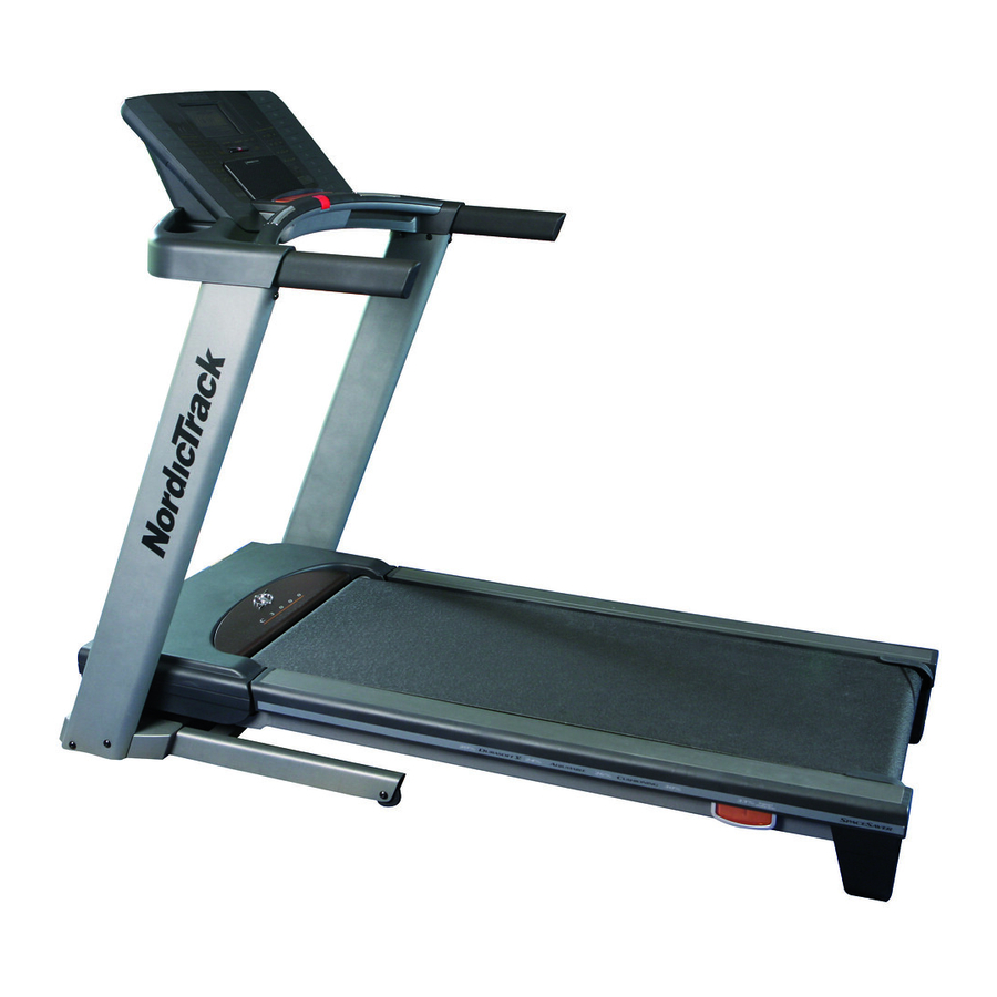
NordicTrack C3000 Treadmill User Manual
Uk manual
Hide thumbs
Also See for C3000 Treadmill:
- Gebruiksaanwijzing (40 pages) ,
- Bedienungsanleitung (40 pages) ,
- Manuel de l'utilisateur (40 pages)
Table of Contents
Advertisement
Model No. NETL16807.0
Serial No.
Write the serial number in the space
above for reference.
Serial Number
Decal
QUESTIONS?
As a manufacturer, we are commit-
ted to providing complete customer
satisfaction. If you have questions,
or if there are missing parts,
please contact us at the numbers
or addresses listed below:
Call: 08457 089 009
Outside UK: 0 (44) 113 3877133
Fax: 0 (44) 113 3877125
E-mail: csuk@iconeurope.com
Write:
ICON Health & Fitness, Ltd.
Unit 4
Revie Road Industrial Estate
Revie Road, Beeston
Leeds, LS11 8JG,
UK
CAUTION
Read all precautions and instruc-
tions in this manual before using
this equipment. Save this manual
for future reference.
With Universal Dock for iPod
®
USER'S MANUAL
Advertisement
Table of Contents
Troubleshooting

Related Manuals for NordicTrack C3000 Treadmill


Summary of Contents for NordicTrack C3000 Treadmill
- Page 1 With Universal Dock for iPod ® Model No. NETL16807.0 Serial No. USER'S MANUAL Write the serial number in the space above for reference. Serial Number Decal QUESTIONS? As a manufacturer, we are commit- ted to providing complete customer satisfaction. If you have questions, or if there are missing parts, please contact us at the numbers or addresses listed below:...
-
Page 2: Table Of Contents
Apply the decal in the location shown. Note: The decals may not be shown at actual size. NordicTrack is a registered trademark of ICON IP, Inc. iPod is a trademark of Apple Computer, Inc., registered in the U.S. and other countries... -
Page 3: Important Precautions
IMPORTANT PRECAUTIONS WARNING: To reduce the risk of serious injury, read all important precautions and in- structions in this manual and all warnings on your treadmill before using your treadmill. ICON as- sumes no responsibility for personal injury or property damage sustained by or through the use of this product. - Page 4 19. Never leave the treadmill unattended while it less instructed to do so by an authorized ser- is running. Always remove the key, unplug vice representative. Servicing other than the the power cord, and switch the reset/off cir- procedures in this manual should be performed cuit breaker to the off position when the by an authorized service representative only.
- Page 5 Power Lines Service Entrance Conductors 75 Ohm Terminal Service Entrance Equipment Power Service Grounding Ground Electrode System (e.g. Clamps Interior Metal Water Pipe) SAVE THESE INSTRUCTIONS...
-
Page 6: Before You Begin
BEFORE YOU BEGIN Thank you for selecting the revolutionary NordicTrack ® ing this manual, please see the front cover of this man- C 3000 treadmill with Universal Dock for iPod . The C ual. To help us assist you, note the product model ®... -
Page 7: Assembly
ASSEMBLY Assembly requires two persons. Set the treadmill in a cleared area and remove all packing materials. Do not dispose of the packing materials until assembly is completed. Note: The underside of the treadmill walking belt is coated with high-performance lubricant. During shipping, a small amount of lubricant may be transferred to the top of the walking belt or the shipping carton. - Page 8 2. Make sure that the power cord is unplugged. With the help of a second person, carefully tip the treadmill onto its left side. Partially fold the Hole Frame (56) so that the treadmill is more stable; do not fully fold the Frame yet. Cut the tie securing the Upright Wire (38) to the Base (83).
- Page 9 5. Set the Right Upright Spacer (79) on the Base (83). Be careful not to pinch the Upright Wire (38). With the help of a second person, hold a Bolt Spacer (80) inside the lower end of the Right Upright (78). Insert a 3/8" x 4 1/4" Bolt (6) with a 3/8"...
- Page 10 8. With the help of a second person, hold the handrail assembly near the Right Upright (78) and the Left Upright (74). Connect the Upright Wire (38) to the console wire. See the inset Handrail drawing. The connectors should slide to- Assembly gether easily and snap into place.
- Page 11 11. Insert the wires from the console assembly into the handrail assembly. Attach the console assembly to the handrail as- Console sembly with four 1/4" x 3/4" Bolts (5). Be care- Assembly ful not to pinch the wires. Handrail Assembly Wires 12.
- Page 12 Before operating the television, you must connect a 75 ohm CATV cable to the 75 ohm terminal on the treadmill, a VCR or DVD player to the audio/video input jack, or a personal audio/video player to the audio/video jack on the console. Note: Use a CATV cable to connect to an external source such as a cable box, analog cable, satellite TV box, or VCR.
-
Page 13: How To Use The Chest Pulse Sensor
HOW TO USE THE CHEST PULSE SENSOR HOW TO PUT ON THE CHEST PULSE SENSOR • Store the chest pulse sensor in a warm, dry place. Do not store the chest pulse sensor in a plastic bag The chest pulse sensor consists of two components: or other container that may trap moisture. -
Page 14: Operation And Adjustment
OPERATION AND ADJUSTMENT THE PRE-LUBRICATED WALKING BELT Your treadmill features a walking belt coated with high-performance lubricant. IMPORTANT: Never apply sili- cone spray or other substances to the walking belt or the walking platform. Such substances will deterio- rate the walking belt and cause excessive wear. HOW TO PLUG IN THE POWER CORD This product must be earthed. - Page 15 CONSOLE DIAGRAM Integrated Universal Dock for iPod FEATURES OF THE CONSOLE trainer coaches you and motivates you through every step of your workout. One iFIT card is included. The treadmill console offers an impressive array of Additional iFIT cards are available separately. To pur- features designed to make your workouts more effec- chase iFIT cards at any time, call the telephone number on the front cover of this manual.
- Page 16 HOW TO TURN ON THE POWER HOW TO USE THE MANUAL MODE IMPORTANT: If the treadmill has been exposed to 1. Insert the key into the console. cold temperatures, allow it to warm to room tem- perature before turning on the power. If you do not See HOW TO TURN ON THE POWER at the left.
- Page 17 5. Select a display mode and follow your progress 6. Measure your heart rate if desired. with the exercise information on the screen. You can measure your heart rate using either the The console offers three display modes. The dis- handgrip pulse sensor or the chest pulse sensor play mode that you select will determine which (see page 13 for information about the chest pulse...
- Page 18 HOW TO USE A WEIGHT LOSS WORKOUT and incline settings programmed for the second segment. Note: The screen has a tuner mode, an 1. Insert the key into the console. RCA mode, and an MP4 mode. The workout profile can be displayed only while the MP4 mode or the See HOW TO TURN ON THE POWER on page RCA mode is selected.
- Page 19 HOW TO CREATE A LEARN WORKOUT cline setting can be programmed for each seg- ment. To program a speed setting and an incline 1. Insert the key into the console. setting for the first segment, simply adjust the speed and incline of the treadmill as desired by See HOW TO TURN ON THE POWER on page pressing the Speed and Incline buttons.
- Page 20 HOW TO USE A LEARN WORKOUT The learn workout will function in the same way as a weight loss workout (see step 3 on page 18). 1. Insert the key into the console. If desired, you can redesign the workout while See HOW TO TURN ON THE POWER on page using it.
- Page 21 HOW TO USE THE CUSTOM WORKOUT CENTER mill will automatically adjust to the speed and in- cline settings programmed for the second segment. 1. Insert the key into the console. Note: The screen has a tuner mode, an RCA mode, and an MP4 mode. The workout profile can See HOW TO TURN ON THE POWER on page be displayed only while the MP4 mode or the RCA mode is selected.
- Page 22 HOW TO USE THE FITNESS AGE CALCULATOR Select your age, height, and weight by repeatedly pressing the increase and decrease buttons for The Fitness Age Calculator measures your approxi- each selection. Press the Start Fitness Test button mate fitness age. Your fitness age is the average age after each selection.
- Page 23 HOW TO USE AN IFIT CARD 3. Press the Start button to start the workout. 1. Insert the key into the console. A moment after you press the button, the treadmill will automatically adjust to the first speed and in- See HOW TO TURN ON THE POWER on page cline settings of the workout.
- Page 24 HOW TO OPERATE THE PERSONAL TELEVISION seconds. To turn on or turn off the sound, press the Mute button. IMPORTANT: Before operating the television, you must connect a 75 ohm CATV cable or a VCR to the To use earphones or headphones (not included), 75 ohm terminal on the treadmill, a VCR or DVD plug them into the headphone jack near the key on player to the three audio/video RCA jacks, or a per-...
- Page 25 THE INFORMATION MODE Adjust the settings, if desired, by pressing the Volume buttons. The console features an information mode that allows 3. Press the Stop button again and add or delete you to view treadmill usage information and select a system of measurement for the console.
- Page 26 HOW TO ADJUST THE CUSHIONING SYSTEM Platform Remove the key from the console and unplug the Cushion power cord. The treadmill features a cushioning sys- tem that reduces the impact as you walk or run on the treadmill. To increase the firmness of the walking plat- form, step off the treadmill and slide the platform cush- Increase ions toward the front of the treadmill.
-
Page 27: How To Fold And Move The Treadmill
HOW TO FOLD AND MOVE THE TREADMILL HOW TO FOLD THE TREADMILL FOR STORAGE Before folding the treadmill, adjust the incline to the lowest position. If you do not do this, you may damage the treadmill when you fold it. Remove the key and unplug the power cord. - Page 28 HOW TO LOWER THE TREADMILL FOR USE 1. Hold the upper end of the treadmill with your right hand. Pull the latch knob to the left and hold it (it may be neces- sary to push the frame forward as you pull the knob to the left).
-
Page 29: Troubleshooting
TROUBLESHOOTING Most treadmill problems can be solved by following the steps below. Find the symptom that applies, and follow the steps listed. If further assistance is needed, please see the front cover of this manual. PROBLEM: The power does not turn on SOLUTION: a. - Page 30 Remove the three #8 x 3/4" Screws (12) and care- fully pivot the Hood (61) off. Locate the Reed Switch (71) and the Magnet (50) on the left side of the Pulley (51). Turn the Pulley until the Magnet is aligned with the Reed Switch. 1/8 in.
- Page 31 PROBLEM: The walking belt is off-center or slips when walked on SOLUTION: a. If the walking belt is off-center, first remove the key and UNPLUG THE POWER CORD. If the walking belt has shifted to the left, use the hex key to turn the left rear roller bolt clockwise 1/2 of a turn;...
- Page 32 PROBLEM: Television reception is poor SOLUTION: a. Check for the problems listed below and follow the applicable instructions. • Ignition (black spots or horizontal streaks that appear or a picture that flutters or drifts)—Usually this is caused by interference from automobile ignition systems, neon lamps, electric drifts, or other electric appliances.
-
Page 33: Exercise Guidelines
EXERCISE GUIDELINES Burning Fat—To burn fat effectively, you must exer- WARNING: cise at a low intensity level for a sustained period of Before beginning this time. During the first few minutes of exercise, your or any exercise program, consult your physi- body uses carbohydrate calories for energy. -
Page 34: Part List
PART LIST—Model No. NETL16807.0 R0108A To locate the parts listed below, see the EXPLODED DRAWING near the end of this manual. Key No. Qty. Description Key No. Qty. Description #8 x 1/2" Screw Front Roller/Pulley #8 x 1" Screw 15 1/2" Wire Tie Hex Key Storage Latch 3/8"... - Page 35 Key No. Qty. Description Key No. Qty. Description Pulse Bar Ground Wire Chest Pulse Receiver Latch Endcap Receiver Screw iFIT Card Kit PAL Connector Lift Motor Spacer AV Input #8 x 2" Screw Rear Roller Plate Right Handrail Trim Incline Motor Wire Rear Roller Ground Wire Static Warning Decal Foot Rail Cover...
- Page 36 EXPLODED DRAWING A—Model No. NETL16807.0 R0108A...
- Page 37 EXPLODED DRAWING B—Model No. NETL16807.0 R0108A...
- Page 38 EXPLODED DRAWING C—Model No. NETL16807.0 R0108A...
- Page 39 EXPLODED DRAWING D—Model No. NETL16807.0 R0108A...
- Page 40 ORDERING REPLACEMENT PARTS To order replacement parts, please see the front cover of this manual. To help us assist you, be prepared to pro- vide the following information when contacting us: • the model number and serial number of the product (see the front cover of this manual) •...
Need help?
Do you have a question about the C3000 Treadmill and is the answer not in the manual?
Questions and answers
Il mio tapis roulant nordic track C3000 si accende il display premendo start ma non parte
The NordicTrack C3000 treadmill may display information but not start when pressing the start button due to the following reasons:
1. Key Not Inserted – Ensure that the key is properly inserted into the console.
2. Reset/Off Circuit Breaker Tripped – Check the reset/off circuit breaker on the treadmill frame near the power cord. If it has tripped, reset it.
3. Power Cord Issues – Verify that the power cord is securely plugged into a properly earthed outlet and that no incompatible extension cords are used.
4. Incompatible Outlet – The treadmill is not compatible with RCD-equipped outlets, so try using a different outlet.
If the issue persists, further troubleshooting may be needed.
This answer is automatically generated