Table of Contents
Advertisement
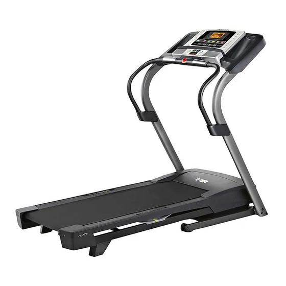
Model No. HETL89711.0
Serial No.
USER'S MANUAL
Write the serial number in the space
above for reference.
Serial Number
Decal
QUESTIONS?
If you have questions, or if there are
missing parts, please contact us:
UNITED KINGDOM
Call: 08457 089 009
From Ireland: 053 92 36102
Website: www.iconsupport.eu
E-mail: csuk@iconeurope.com
Write:
ICON Health & Fitness, Ltd.
c/o HI Group PLC
Express Way
CASTLEFORD
WF10 5QJ
UNITED KINGDOM
AUSTRALIA
Call: 1800 993 770
E-mail: australiacc@iconfitness.com
Write:
ICON Health & Fitness
PO Box 635
WINSTON HILLS NSW 2153
AUSTRALIA
CAUTION
Read all precautions and instruc-
tions in this manual before using
this equipment. Save this manual
www.iconeurope.com
for future reference.
Advertisement
Table of Contents

Related Manuals for Healthrider H97t Treadmill


Summary of Contents for Healthrider H97t Treadmill
- Page 1 Model No. HETL89711.0 Serial No. USER’S MANUAL Write the serial number in the space above for reference. Serial Number Decal QUESTIONS? If you have questions, or if there are missing parts, please contact us: UNITED KINGDOM Call: 08457 089 009 From Ireland: 053 92 36102 Website: www.iconsupport.eu E-mail: csuk@iconeurope.com...
-
Page 2: Table Of Contents
Apply the decal in the location shown. Note: The decals may not be shown at actual size. HEALTHRIDER is a registered trademark of ICON IP, Inc. -
Page 3: Important Precautions
IMPORTANT PRECAUTIONS WARNING: To reduce the risk of serious injury, read all important precautions and instructions in this manual and all warnings on your treadmill before using your treadmill. ICON assumes no responsibility for personal injury or property damage sustained by or through the use of this product. - Page 4 20. Do not attempt to raise, lower, or move the the treadmill, and before performing the treadmill until it is properly assembled. (See maintenance and adjustment procedures ASSEMBLY on page 6, and HOW TO FOLD described in this manual. Never remove the AND MOVE THE TREADMILL on page 22.) motor hood unless instructed to do so by an You must be able to safely lift 45 lbs.
-
Page 5: Before You Begin
Thank you for selecting the revolutionary reading this manual, please see the front cover of this HEALTHRIDER H97T treadmill. The H97T treadmill manual. To help us assist you, please note the product ® offers an impressive selection of features designed model number and serial number before contacting us. -
Page 6: Assembly
ASSEMBLY Assembly requires two persons. Set the treadmill in a cleared area and remove all packing materials. Do not dispose of the packing materials until assembly is completed. After shipping, there may be an oily substance on the exterior of the treadmill. This is normal. If there is an oily substance on the treadmill, simply wipe it off with a soft cloth and a mild, non-abrasive cleaner. - Page 7 1. Make sure that the power cord is unplugged. Remove the ties securing the Upright Wire (70) to the Base (80). Pull the Upright Wire and the base ground wire (A) through the indicated hole in the Base. Attach the base ground wire (A) to the Base (80) with a #8 x 1/2"...
-
Page 8: Be Careful Not To Pinch The Wires. Insert A
3. Hold the Left Upright (75) against the Base (80). Be careful not to pinch the wires. Insert a 3/8" x 3 1/2" Screw (4) with a 3/8" Star Washer (5) into the top hole in the Left Upright. Insert the 3/8" x 3 1/2" Screw (4) partially through the Left Upright (75). - Page 9 5. Attach the Console Frame (87) to the Left and Right Uprights (75, 76) with two 5/16" x 3 1/4" Screws (7) and two 5/16" Star Washers (8); do not fully tighten the Screws yet. 6. Insert the upper end of the Left Handrail (71) into the tube on the Console Frame (87).
- Page 10 7. Locate the tie in the console assembly. Use the tie to pull the ground wires out of the hole in the Console console assembly. Assembly With the help of a second person, hold the con- sole assembly near the Left Upright (75). Connect the Upright Wire (70) to the console Ground wire.
- Page 11 9. Attach the Pulse Bar Bottom (90) to the console assembly with six #8 x 3/4" Screws (6); start all six Screws, and then tighten them. Do not Console overtighten the Screws. Assembly 10. Attach the Left Handrail Cover (73) to the lower end of the Left Handrail (71) with two #8 x 3/4"...
-
Page 12: Base (80)
11. Raise the Frame (49) to the position shown. Have a second person hold the Frame until step 12 is completed. Orient the Storage Latch (51) so that the large barrel and the latch knob are oriented as shown. Attach the lower end of the Storage Latch (51) to the Base (80) with a 3/8"... -
Page 13: Operation And Adjustment
OPERATION AND ADJUSTMENT HOW TO PLUG IN THE POWER CORD Follow the steps below to plug in the power cord. This product must be earthed. If it should malfunc- 1. Plug the indicated end of the power cord into the tion or break down, earthing provides a path of least socket on the treadmill. -
Page 14: Console Diagram/Features
CONSOLE DIAGRAM FEATURES OF THE CONSOLE Live module at any time, go to www.iFit.com or call the telephone number on the front cover of this manual. The treadmill console offers an impressive array of features designed to make your workouts more effec- tive and enjoyable. - Page 15 HOW TO TURN ON THE POWER HOW TO USE THE MANUAL MODE IMPORTANT: If the treadmill has been exposed to 1. Insert the key into the console. cold temperatures, allow it to warm to room tem- perature before turning on the power. If you do not See HOW TO TURN ON THE POWER at the left.
- Page 16 4. Change the incline of the treadmill as desired. (1/4 mile). As you exercise, the flashing rectangle will show your progress. The My Trail tab will also To change the incline of the treadmill, press the show the number of laps you complete. Incline increase or decrease button or one of the numbered 1 Step Incline buttons.
- Page 17 6. Measure your heart rate if desired. 7. When you are finished exercising, remove the key from the console. Note: If you use the handgrip heart rate moni- tor and the optional chest heart rate monitor at Step onto the foot rails, press the Stop button, and the same time, the console will not display your adjust the incline of the treadmill to the lowest heart rate accurately.
- Page 18 HOW TO USE AN ONBOARD WORKOUT The workout will continue in this way until the last segment of the profile flashes in the display and the 1. Insert the key into the console. last segment ends. The walking belt will then slow to a stop.
-
Page 19: To Use Ifit Live Workout
HOW TO USE AN IFIT LIVE WORKOUT Press the iFit Live button to download the next workout in your schedule. Press the My Trainer Note: To use an iFit Live workout, you must have an button, the My Maps button, the World Tour but- optional iFit Live module. - Page 20 6. Follow your progress with the displays. Next, press the play button on your MP3 player, CD player, See step 5 on page 16. or other personal audio player. Adjust the volume on your per- The My Trail tab will show a map of the trail you are sonal audio player or press the volume increase and walking or running or it will show a track and the decrease buttons on the console.
- Page 21 THE INFORMATION MODE console. However, when you remove the key, the displays will remain lit, although the buttons will The console features an information mode that keeps not function. If the demo mode is turned on, the track of treadmill information and allows you to person- word ON will appear in the matrix.
-
Page 22: How To Fold And Move The Treadmill
HOW TO FOLD AND MOVE THE TREADMILL HOW TO FOLD THE TREADMILL HOW TO MOVE THE TREADMILL To avoid damaging the treadmill, adjust the incline Before moving the treadmill, fold it as described at the to the lowest position before you fold the treadmill. left. -
Page 23: Troubleshooting
TROUBLESHOOTING Most treadmill problems can be solved by follow- SYMPTOM: The console displays remain lit when ing the simple steps below. Find the symptom that you remove the key from the console applies, and follow the steps listed. If further assis- tance is needed, see the front cover of this manual. - Page 24 Lower the treadmill (see HOW TO LOWER THE the minimum level. This will calibrate the incline TREADMILL FOR USE on page 22). Remove system. If the incline system does not calibrate, the three #8 x 3/4" Screws (6). Carefully slide the press the Stop button, and then press the Incline Motor Hood (57) off.
- Page 25 SYMPTOM: The walking belt is not centered SYMPTOM: The walking belt slips when walked on between the foot rails. IMPORTANT: If the walking belt rubs against the foot rails, the walking belt a. First, remove the key and UNPLUG THE POWER may be damaged.
-
Page 26: Exercise Guidelines
EXERCISE GUIDELINES Burning Fat—To burn fat effectively, you must exer- WARNING: cise at a low intensity level for a sustained period of Before beginning this time. During the first few minutes of exercise, your or any exercise program, consult your physi- body uses carbohydrate calories for energy. -
Page 27: Part List
PART LIST Model No. HETL89711.0 R0412A Key No. Qty. Description Key No. Qty. Description #8 x 1/2" Ground Screw Right Footrail Cap 3/8" x 2 1/2" Bolt Left Footrail Cap 3/8" Nut Idler Roller 3/8" x 3 1/2" Screw Motor Hood 3/8"... -
Page 28: Exploded Drawing
EXPLODED DRAWING A Model No. HETL89711.0 R0412A... - Page 29 EXPLODED DRAWING B Model No. HETL89711.0 R0412A...
- Page 30 EXPLODED DRAWING C Model No. HETL89711.0 R0412A...
- Page 31 EXPLODED DRAWING D Model No. HETL89711.0 R0412A...
-
Page 32: Ordering Replacement Parts
ORDERING REPLACEMENT PARTS To order replacement parts, please see the front cover of this manual. To help us assist you, be prepared to pro- vide the following information when contacting us: • the model number and serial number of the product (see the front cover of this manual) • the name of the product (see the front cover of this manual) • t he key number and description of the replacement part(s) (see the PART LIST and the EXPLODED DRAWING near the end of this manual) RECYCLING INFORMATION This electronic product must not be disposed of in municipal waste.
Need help?
Do you have a question about the H97t Treadmill and is the answer not in the manual?
Questions and answers