Table of Contents
Advertisement
healthrider.com
Model No. HRTL70014C.3
Serial No.
Write the serial number in the space
above for reference.
Serial
Number
Decal
ACTIVATE YOUR
WARRANTY
To register your product and
activate your warranty today,
go to iconservice.ca.
CUSTOMER CARE
Call toll-free 1-888-936-4266
Mon.–Fri. 7:30 a.m.–4:30 p.m. ET
(excluding holidays)
or email us at
customerservice@iconcanada.ca
Please do not contact the store.
CAUTION
Read all precautions and instruc-
tions in this manual before using
this equipment. Save this manual
for future reference.
USER'S MANUAL
Advertisement
Table of Contents

Related Manuals for Healthrider H70t


Summary of Contents for Healthrider H70t
- Page 1 Model No. HRTL70014C.3 USER’S MANUAL Serial No. Write the serial number in the space above for reference. Serial Number Decal ACTIVATE YOUR WARRANTY To register your product and activate your warranty today, go to iconservice.ca. CUSTOMER CARE Call toll-free 1-888-936-4266 Mon.–Fri.
-
Page 2: Table Of Contents
Apply the decal in the location shown. Note: The decals may not be shown at actual size. 305284 HEALTHRIDER is a registered trademark of ICON Health & Fitness, Inc. -
Page 3: Important Precautions
IMPORTANT PRECAUTIONS WARNING: To reduce the risk of burns, fire, electric shock, or injury to persons, read all important precautions and instructions in this manual and all warnings on your treadmill before using your treadmill. ICON assumes no responsibility for personal injury or property damage sus- tained by or through the use of this product. - Page 4 19. Always stand on the foot rails when starting able to safely lift 45 lbs. (20 kg) to move the or stopping the walking belt. Always hold the treadmill. handrails while using the treadmill. 26. When folding or moving the treadmill, make 20.
-
Page 6: Before You Begin
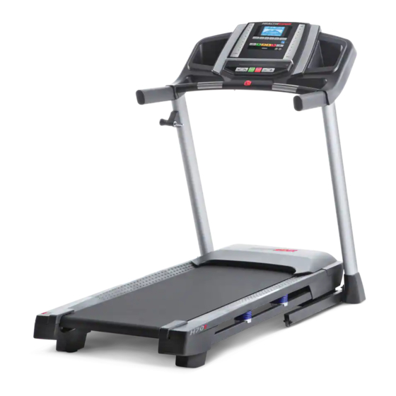
Thank you for selecting the new HEALTHRIDER manual. To help us assist you, note the product model ® H70T treadmill. The H70T treadmill provides an number and serial number before contacting us. The impressive selection of features designed to make your model number and the location of the serial number workouts at home more effective and enjoyable. -
Page 7: Part Identification Chart
PART IDENTIFICATION CHART Use the drawings below to identify small parts used for assembly. The number in parentheses below each draw- ing is the key number of the part, from the PART LIST near the end of this manual. The number following the key number is the quantity used for assembly. -
Page 8: Assembly
ASSEMBLY • Assembly requires two persons. • To identify small parts, see page 7. • Place all parts in a cleared area and remove the • Assembly requires the following tools: packing materials. Do not dispose of the packing the included hex keys materials until you finish all assembly steps. - Page 9 2. Make sure that the power cord is unplugged. Remove the tie securing the Upright Wire (81) to the front of the Base (6). Next, identify the Right Upright (90). Have a sec- ond person hold the Right Upright near the Base (6).
- Page 10 4. Hold the Right Upright (90) against the Base (6). Make sure not to pinch the Upright Wire (81). Attach the Right Upright (90) with two 3/8" x 2 3/8" Screws (7), a 3/8" x 1 1/4" Screw (63), a 3/8" x 1 3/4" Screw (62), and four 3/8" Star Washers (13) as shown;...
- Page 11 6. Identify the Right Handrail (84). Attach the Right Handrail (84) to the Right Upright (90) with two 5/16" x 3" Screws (28) and two 5/16" Star Washers (11); start both Screws, and then tighten them. Make sure not to pinch the Upright Wire (81).
- Page 12 8. If there are four screws (F) preattached inside the Right and Left Handrails (84, 85), remove and discard the screws. IMPORTANT: To avoid damaging the Pulse Crossbar (93), do not use power tools and do not overtighten the #10 x 1 1/4" Screws (9). Orient the Pulse Crossbar (93) as shown.
- Page 13 10. Set the console assembly (G) on the Right and Left Handrails (84, 85). Make sure that no wires are pinched. Insert the excess Upright Wire (81) into the Right Upright (90). Attach the console assembly (G) with four 1/4" x 1/2" Screws (4); do not fully tighten the Screws yet.
- Page 14 12. Attach the Right and Left Trays (27, 36) with four #8 x 1/2" Screws (1). 13. Orient the Storage Latch (26) as shown. Attach the Storage Latch to the Left Upright (89) with two 1/4" x 4 1/2" Screws (8) and two 1/4" Star Washers (41);...
- Page 15 14. Firmly tighten the four 3/8" x 2 3/8" Screws (7), the two 3/8" x 1 3/4" Screws (62), and the two 3/8" x 1 1/4" Screws (63). Next, set the Left Inner Base Cover (66) onto the lower end of the Left Upright (89). Then, slide the Left Base Cover (82) downward and press it onto the Left Inner Base Cover.
-
Page 16: How To Use The Treadmill
HOW TO USE THE TREADMILL HOW TO CONNECT THE POWER CORD more amps. To avoid overloading the circuit, do not plug other electrical devices, except for low- Use a Surge Suppressor power devices such as cell phone chargers, into the surge suppressor or into an outlet on the same Your treadmill, like other electronic equipment, can be circuit. - Page 17 CONSOLE DIAGRAM FEATURES OF THE CONSOLE To turn on the power, see page 18. To use the manual mode, see page 18. To use an onboard workout, see page 19. To use an 8-week weight The treadmill console offers a selection of features loss workout, see page 20.
- Page 18 HOW TO TURN ON THE POWER HOW TO USE THE MANUAL MODE IMPORTANT: If the treadmill has been exposed to 1. Insert the key into the console. cold temperatures, allow it to warm to room tem- perature before you turn on the power. If you do See HOW TO TURN ON THE POWER at the left.
- Page 19 5. Follow your progress with the displays. 7. Turn on the fan if desired. Time/Distance display—When the manual mode The fan features several is selected, this display will show the elapsed time. speed settings. Press the fan When a workout is selected, the display will show buttons repeatedly to select a the time remaining in the workout rather than the fan speed or to turn on or turn...
- Page 20 HOW TO USE AN 8-WEEK WEIGHT-LOSS Each workout is divided into segments. One speed setting and one incline setting are programmed WORKOUT for each segment. Note: The same speed setting 1. Insert the key into the console. and/or incline setting may be programmed for con- secutive segments.
- Page 21 7. Measure your heart rate if desired. HOW TO USE THE SOUND SYSTEM See step 6 on page 19. To play music or audio books through the console sound system while you exercise, plug a 3.5 mm male 8. Turn on the fan if desired. to 3.5 mm male audio cable (not included) into the jack on the console and into a jack on your personal audio See step 7 on page 19.
-
Page 22: How To Fold And Move The Treadmill
HOW TO FOLD AND MOVE THE TREADMILL HOW TO FOLD THE TREADMILL HOW TO MOVE THE TREADMILL To avoid damaging the treadmill, adjust the incline Before moving the treadmill, fold it as described at to zero before you fold the treadmill. Then, remove the left. -
Page 23: Maintenance And Troubleshooting
MAINTENANCE AND TROUBLESHOOTING MAINTENANCE c. Check the power switch located on the treadmill frame near the power cord. If the switch protrudes Regular maintenance is important for optimal per- as shown, the switch has tripped. To reset the formance and to reduce wear. Inspect and properly power switch, wait for five minutes and then press tighten all parts each time the treadmill is used. - Page 24 SYMPTOM: The incline of the treadmill does not c. Your treadmill features a walking belt coated change correctly with high-performance lubricant. IMPORTANT: Never apply silicone spray or other substances a. Hold down the Stop button and the Speed increase to the walking belt or the walking platform unless button, insert the key into the console, and then instructed to do so by an authorized service release the Stop button and the Speed increase...
- Page 25 b. If the walking belt slips when walked on, first remove the key and UNPLUG THE POWER CORD. Using the hex key, turn both idler roller screws clockwise, 1/4 of a turn. When the walking belt is correctly tightened, you should be able to lift each edge of the walking belt 2 to 3 in.
-
Page 26: Exercise Guidelines
EXERCISE GUIDELINES Burning Fat—To burn fat effectively, you must exer- WARNING: cise at a low intensity level for a sustained period of Before beginning this time. During the first few minutes of exercise, your or any exercise program, consult your physi- body uses carbohydrate calories for energy. -
Page 27: Part List
PART LIST Model No. HRTL70014C.3 R0617A Key No. Qty. Description Key No. Qty. Description #8 x 1/2" Screw 1/4" x 1 1/4" Patch Screw #8 x 3/4" Screw Drive Motor #8 x 1/2" Screw Motor Belt 1/4" x 1/2" Screw Frame #10 Star Washer Left Rear Foot... -
Page 28: Exploded Drawing
EXPLODED DRAWING A Model No. HRTL70014C.3 R0617A... - Page 29 EXPLODED DRAWING B Model No. HRTL70014C.3 R0617A...
- Page 30 EXPLODED DRAWING C Model No. HRTL70014C.3 R0617A...
- Page 31 EXPLODED DRAWING D Model No. HRTL70014C.3 R0617A...
-
Page 32: Ordering Replacement Parts
ORDERING REPLACEMENT PARTS To order replacement parts, please see the front cover of this manual. To help us assist you, be prepared to provide the following information when contacting us: • the model number and serial number of the product (see the front cover of this manual) •...
Need help?
Do you have a question about the H70t and is the answer not in the manual?
Questions and answers
When i step on it the treadmill stops help
The HealthRider H70T treadmill may stop when you step on it due to insufficient lubrication on the walking belt. The manual advises against applying silicone spray or other substances unless instructed by an authorized service representative. If the walking belt still slows when walked on, refer to the front cover of the manual for further instructions.
This answer is automatically generated
H70t turns on then shuts off. I need some help
The Healthrider H70t treadmill turns on, but the motor does not run. The user reports that the LCD screen comes on, the console safety key is inserted, and the incline motor fan is turning. This suggests that power is reaching the treadmill, but the main motor may not be functioning due to a faulty motor, a damaged motor controller, or a wiring issue. Further troubleshooting is needed to check for error codes, loose connections, or a failed motor control board.
This answer is automatically generated
what size of hex key is for the treadmill?
The included hex key is used to adjust the walking belt on the HealthRider H70T treadmill. However, the specific size of the hex key is not mentioned in the provided context.
This answer is automatically generated
Doit on lubrifier le tapis roulant et si oui à quels endroits?
Yes, the HealthRider H70T treadmill should be lubricated. The treadmill belt is specified as a "2 Ply Lubricated Treadmill Belt," indicating that lubrication is necessary for its proper functioning. The lubrication should be applied between the treadmill belt and the deck to reduce friction and ensure smooth operation. Follow the manufacturer's instructions in the manual for the correct application process and frequency.
This answer is automatically generated