Table of Contents
Advertisement
www.healthrider.com
Model No. HRTL80511.0
Serial No.
USER'S MANUAL
Write the serial number in the space
above for reference.
Serial Number
Decal
QUESTIONS?
If you have questions, or if parts
are damaged or missing, DO NOT
CONTACT THE STORE; please
contact Customer Care.
IMPORTANT: Please register this
product (see the limited warranty
on the back cover of this manual)
before contacting Customer Care.
CALL TOLL-FREE:
1-888-922-4222
Mon.–Fri. 6 a.m.–6 p.m. MT
Sat. 8 a.m.–4 p.m. MT
ON THE WEB:
www.healthriderservice.com
CAUTION
Read all precautions and instruc-
tions in this manual before using
this equipment. Save this manual
for future reference.
Advertisement
Table of Contents

Subscribe to Our Youtube Channel
Related Manuals for Healthrider H80t Treadmill


Summary of Contents for Healthrider H80t Treadmill
- Page 1 Model No. HRTL80511.0 Serial No. USER’S MANUAL Write the serial number in the space above for reference. Serial Number Decal QUESTIONS? If you have questions, or if parts are damaged or missing, DO NOT CONTACT THE STORE; please contact Customer Care.
-
Page 2: Table Of Contents
Apply the decal in the location shown. Note: The decals may not be shown at actual size. HEALTHRIDER is a registered trademark of ICON IP, Inc. -
Page 3: Important Precautions
15. To purchase a surge suppressor, informed of all warnings and precautions. see your local HEALTHRIDER dealer or call the telephone number on the front cover of 3. Use the treadmill only as described. - Page 4 DANGER: 20. Never leave the treadmill unattended while Always unplug the power it is running. Always remove the key, unplug cord immediately after use, before clean- the power cord, and press the power switch ing the treadmill, and before performing the into the off position when the treadmill is not maintenance and adjustment procedures in use.
-
Page 5: Before You Begin
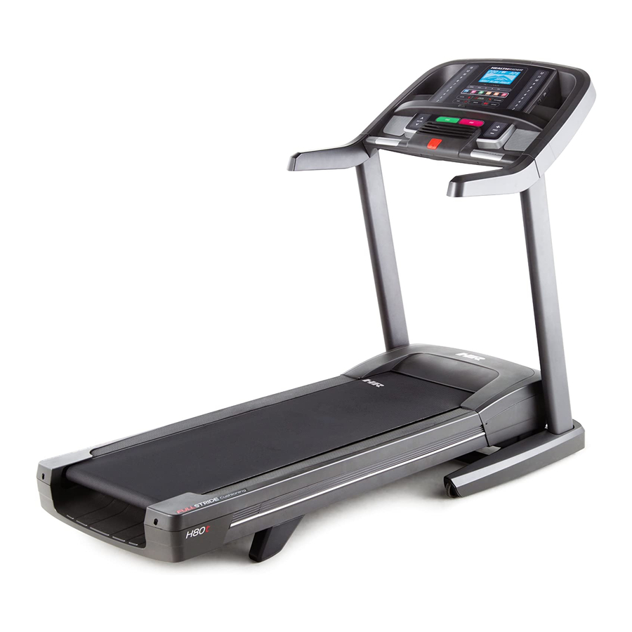
Thank you for selecting the revolutionary reading this manual, please see the front cover of this HEALTHRIDER H80T treadmill. The H80T treadmill manual. To help us assist you, please note the product ® offers an impressive selection of features designed model number and serial number before contacting us. -
Page 6: Part Identification Chart
PART IDENTIFICATION CHART Use the drawings below to identify small parts used for assembly. The number in parentheses below each draw- ing is the key number of the part, from the PART LIST near the end of this manual. The number following the key number is the quantity used for assembly. -
Page 7: Assembly
ASSEMBLY • To hire an authorized service technician to assem- • To identify small parts, see page 6. ble your exercise equipment, call 1-800-445-2480. • Assembly requires the following tools: • Assembly requires two persons. the included hex keys • Place all parts in a cleared area and remove the one adjustable wrench packing materials. - Page 8 3. Identify the Left Upright (88), which is marked with a “Left” sticker. Have a second person hold the Left Upright near the Base (91). See the inset drawing. Tie the wire tie in the Left Upright (88) securely around the Upright Wire (77) about 8 in.
- Page 9 5. Identify the Left and Right Base Covers (83, 84). Slide the Left Base Cover onto the Left Upright (88). Slide the Right Base Cover onto the Right Upright (89). Do not press the Base Covers into place yet. 6. Orient the Handrail Brackets (15) so that the bend in the Brackets is positioned as shown.
- Page 10 7. Identify the left and right handrail assemblies (B, Attach the Left Handrail Bottom (42) to the bot- tom of the left handrail assembly (B) with two #8 x 3/4" Screws (2). Attach the Right Handrail Bottom (51) to the bot- tom of the right handrail assembly (C) with two #8 x 3/4"...
- Page 11 9. Set the console assembly face down on a soft surface to avoid scratching the console assem- bly. Remove the two screws (D). Next, lift off the Pulse Bar Bottom (87). Discard the two screws. Console Assembly 10. Slide the Pulse Bar Bottom (87) assembly onto the left and right handrail assemblies (B, C).
- Page 12 11. With the help of a second person, hold the con- Console sole assembly near the Left and Right Uprights Assembly (88, 89). Connect the Upright Wire (77) to the console wire. See the inset drawing. The connectors should slide together easily and snap into place.
- Page 13 13. Tighten the four 3/8" x 2 3/4" Screws (7), and then tighten the four 3/8" x 1 1/4" Screws (8) (only one side is shown). Press the Left and Right Base Covers (83, 84) onto the Base (91) until they snap into place. 14.
- Page 14 15. Attach the upper end of the Storage Latch (58) to the Frame (57) with a 3/8" x 1 3/4" Bolt (6) and a 3/8" Nut (12). 16. Make sure that all parts are properly tightened before you use the treadmill. If there are sheets of plas- tic on the treadmill decals, remove the plastic.
-
Page 15: Operation And Adjustment
OPERATION AND ADJUSTMENT HOW TO PLUG IN THE POWER CORD This product is for use on a nominal 120-volt circuit (see drawing 1). A temporary adapter may be used to connect the surge suppressor to a 2-pole receptacle if DANGER: a properly grounded outlet is not available (see Improper connec- drawing 2). - Page 16 CONSOLE DIAGRAM FEATURES OF THE CONSOLE out results, race against other runners, and access many other features. To purchase an iFit Live mod- ule at any time, go to www.iFit.com or call the tele- The treadmill console offers an impressive array of phone number on the front cover of this manual.
- Page 17 HOW TO TURN ON THE POWER HOW TO USE THE MANUAL MODE IMPORTANT: If the treadmill has been exposed to 1. Insert the key into the console. cold temperatures, allow it to warm to room tem- perature before turning on the power. If you do not See HOW TO TURN ON THE POWER at the left.
- Page 18 4. Change the incline of the treadmill as desired. The Incline tab will show a profile of the incline set- tings of the workout. A new segment will appear at To change the incline of the treadmill, press the the end of each minute. The Speed tab will show a Incline increase or decrease button or one of the profile of the speed settings of the workout.
- Page 19 6. Measure your heart rate if desired. the fan is on when the walking belt is stopped, the fan will turn off automatically after a few minutes. Before using the handgrip heart rate monitor, re- move the sheets of plastic from the metal contacts 8.
- Page 20 HOW TO USE AN ONBOARD WORKOUT progress. The flashing segment of the profile rep- resents the current segment of the workout. The 1. Insert the key into the console. height of the flashing segment indicates the speed or incline setting for the current segment. See HOW TO TURN ON THE POWER on page 17.
- Page 21 HOW TO USE AN IFIT LIVE WORKOUT To stop the workout at any time, press the Stop button. The time will begin to flash in the display. To resume the workout, press the Start button or Note: To use an iFit Live workout, you must have an the Speed increase button.
- Page 22 6. Follow your progress with the displays. Press the iFit Live button to download the next workout in your schedule. Press the My Trainer button, the My Maps button, the World Tour button, See step 5 on page 18. or the Event Training button to download the next workout of that type in your schedule.
- Page 23 THE INFORMATION MODE 3. CONTRAST LVL: Press the Incline increase and decrease buttons to adjust the contrast level of the The console features an information mode that keeps display. track of treadmill information and allows you to person- If a module is connected, you may also select the alize console settings.
- Page 24 HOW TO USE THE STEREO SOUND SYSTEM Next, press the play button Increase on your MP3 player, CD To play music or audio books through the console’s player, or other personal stereo speakers, you must connect your MP3 player, audio player. Adjust the vol- CD player, or other personal audio player to the con- ume on your personal audio Decrease...
-
Page 25: How To Fold And Move The Treadmill
HOW TO FOLD AND MOVE THE TREADMILL HOW TO FOLD THE TREADMILL HOW TO MOVE THE TREADMILL To avoid damaging the treadmill, adjust the incline Before moving the treadmill, fold it as described at the to the lowest position before you fold the treadmill. left. -
Page 26: Troubleshooting
TROUBLESHOOTING Most treadmill problems can be solved by following c. Remove the key from the console, and then the simple steps below. Find the symptom that reinsert it. applies, and follow the steps listed. If further assis- tance is needed, see the front cover of this manual. d. - Page 27 Locate the Reed Switch (55) and the Magnet (54) b. If the walking belt is overtightened, treadmill per- on the left side of the Pulley (53). Turn the Pulley formance may decrease and the walking belt may until the Magnet is aligned with the Reed Switch. become damaged.
- Page 28 SYMPTOM: The walking belt is off-center or slips b. If the walking belt slips when walked on, first re- when walked on move the key and UNPLUG THE POWER CORD. Using the hex key, turn both idler roller screws a. If the walking belt is off-center, first remove the clockwise, 1/4 of a turn.
-
Page 29: Exercise Guidelines
EXERCISE GUIDELINES Burning Fat—To burn fat effectively, you must exer- WARNING: cise at a low intensity level for a sustained period of Before beginning this time. During the first few minutes of exercise, your or any exercise program, consult your physi- body uses carbohydrate calories for energy. -
Page 30: Part List
PART LIST Model No. HRTL80511.0 R1011A Key No. Qty. Description Key No. Qty. Description #8 x 1/2" Screw Right Handrail Bottom #8 x 3/4" Screw Reed Switch Clamp 3/8" x 2" Bolt Drive Roller/Pulley 5/16" x 5/8" Screw Magnet 3/8" x 1" Flat Head Screw Reed Switch 3/8"... - Page 31 Key No. Qty. Description Key No. Qty. Description Console Clamp Console Base Frame Ground Wire – User’s Manual Note: Specifications are subject to change without notice. For information about ordering replacement parts, see the back cover of this manual. *These parts are not illustrated.
-
Page 32: Exploded Drawing
EXPLODED DRAWING A Model No. HRTL80511.0 R1011A... - Page 33 EXPLODED DRAWING B Model No. HRTL80511.0 R1011A...
- Page 34 EXPLODED DRAWING C Model No. HRTL80511.0 R1011A...
- Page 35 EXPLODED DRAWING D Model No. HRTL80511.0 R1011A...
-
Page 36: Ordering Replacement Parts
ORDERING REPLACEMENT PARTS To order replacement parts, please see the front cover of this manual. To help us assist you, be prepared to provide the following information when contacting us: • the model number and serial number of the product (see the front cover of this manual) •...
Need help?
Do you have a question about the H80t Treadmill and is the answer not in the manual?
Questions and answers
hello dear ! what happened when I **** running feeling heavy
If your Healthrider H80T treadmill feels heavy while running, check and properly tighten all parts of the treadmill regularly. Also, ensure the walking belt is properly centered and not overtightened. If necessary, adjust the idler roller screws to center the belt and prevent excessive resistance.
This answer is automatically generated