Table of Contents
Advertisement
2013
Read this manual carefully before operating this vehicle.
Il convient de lire attentivement ce manuel avant la première utilisation du véhicule.
Bitte lesen Sie diese Bedienungsanleitung sorgfältig durch, bevor Sie das Fahrzeug in Betrieb nehmen.
Leggere attentamente questo manuale prima di utilizzare questo veicolo.
OWNER'S SERVICE MANUAL
MANUEL D'ATELIER DU
PROPRIETAIRE
FAHRER- UND
WARTUNGSHANDBUCH
MANUALE DI SERVIZIO DEL
PROPRIETARIO
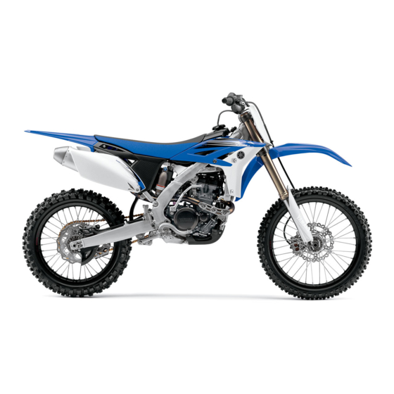
YZ250F(D)
17D-28199-33
Advertisement
Table of Contents

Related Manuals for Yamaha YZ250F(D)


Summary of Contents for Yamaha YZ250F(D)
- Page 1 2013 Read this manual carefully before operating this vehicle. Il convient de lire attentivement ce manuel avant la première utilisation du véhicule. Bitte lesen Sie diese Bedienungsanleitung sorgfältig durch, bevor Sie das Fahrzeug in Betrieb nehmen. Leggere attentamente questo manuale prima di utilizzare questo veicolo. OWNER’S SERVICE MANUAL MANUEL D’ATELIER DU PROPRIETAIRE...
- Page 2 Read this manual carefully before operating this vehicle. This manual should stay with this vehicle if it is sold. Il convient de lire attentivement ce manuel avant la première utilisation du véhicule. Le manuel doit être remis avec le véhicule en cas de vente de ce dernier. Bitte lesen Sie diese Bedienungsanleitung sorgfältig durch, bevor Sie das Fahrzeug in Betrieb nehmen.
- Page 3 2013 2013 Read this manual carefully before operating this vehicle. Read this manual carefully before operating this vehicle. OWNER’S SERVICE MANUAL OWNER’S SERVICE MANUAL YZ250F(D) YZ250F(D) 17D-28199-33-E0 17D-28199-33-E0...
- Page 5 YZ250F(D) OWNER'S SERVICE MANUAL ©2012 by Yamaha Motor Co., Ltd. 1st Edition, April 2012 All rights reserved.Any reprinting or unauthorized use without the written permission of Yamaha Motor Co., Ltd. is expressly prohibited. Printed in Japan...
-
Page 6: Safety Information
Always turn off the engine while re- Congratulations on your purchase of could result in death or serious in- fueling. Take care to not spill any a Yamaha YZ series. This model is jury. gasoline on the engine or exhaust the culmination of Yamaha's vast ex- system. -
Page 7: General Information
HOW TO USE THIS MANUAL FINDING THE REQUIRED PAGE 1. This manual consists of seven chapters; "General Information", "Specifications", "Regular inspec- tion and adjustments", "Engine", "Chassis", "Electrical" and "Tun- ing" 2. The table of contents is at the be- ginning of the manual. Look over the general layout of the book be- fore finding then required chapter and item. - Page 8 2. Numbers "2" are given in the or- 4. A job instruction chart "4" accom- HOW TO READ DESCRIPTIONS der of the jobs in the exploded di- panies the exploded diagram, To help identify parts and clarify pro- agram. A number that is enclosed providing the order of jobs, names cedure steps, there are exploded dia- by a circle indicates a disassem-...
-
Page 9: Table Of Contents
TABLE OF CONTENTS GENERAL INFORMATION SPECIFICATIONS REGULAR INSPECTION AND ADJUSTMENTS ENGINE CHASSIS ELECTRICAL TUNING... -
Page 10: Table Of Contents
CONTENTS CHAPTER 1 CHAPTER 3 CHAPTER 5 REGULAR CHASSIS GENERAL INSPECTION AND INFORMATION ADJUSTMENTS FRONT WHEEL AND REAR WHEEL ....5-1 FRONT BRAKE AND LOCATION OF MAINTENANCE REAR BRAKE ....5-6 IMPORTANT LABELS ..1-1 INTERVALS...... 3-1 FRONT FORK....5-16 DESCRIPTION ....1-5 PRE-OPERATION HANDLEBAR....5-24 CONSUMER... -
Page 11: Important Labels
LOCATION OF IMPORTANT LABELS GENERAL INFORMATION LOCATION OF IMPORTANT LABELS Please read the following important labels carefully before operating this vehicle. CANADA... - Page 12 LOCATION OF IMPORTANT LABELS EUROPE...
- Page 13 LOCATION OF IMPORTANT LABELS AUS, NZ, ZA...
-
Page 14: Location Of Important Labels
LOCATION OF IMPORTANT LABELS Familiarize yourself with the following pictograms and read the explanatory text. Read Owner’s service manual. This unit contains high-pressure nitrogen gas. Mishandling can cause explosion. Do not incinerate, puncture or open. Turn off the main switch after riding to avoid draining the battery. Use unleaded gasoline only. -
Page 15: Description
DESCRIPTION DESCRIPTION Clutch lever 14. Fuel cock Hot starter lever 15. Cold starter knob Front brake lever 16. Air filter Throttle grip 17. Drive chain Radiator cap 18. Shift pedal Fuel tank cap 19. Oil level check window Engine stop switch 20. -
Page 16: Consumer Information
"a" face forward. knowing the serial number of your machine: 1. When ordering parts, you can give the number to your Yamaha dealer for positive identification of the model you own. VALVE JOINT 2. If your machine is stolen, the au- This valve joint "1"... -
Page 17: Checking Of Connection
"1" and reinsert the termi- nal into the connector. 5. Keep away from fire. ALL REPLACEMENT PARTS 1. We recommend to use Yamaha 6. Connect: genuine parts for all replace- • Connector ments. Use oil and/or grease rec- ommended by Yamaha for assembly and adjustment. -
Page 18: Special Tools
SPECIAL TOOLS SPECIAL TOOLS The proper special tools are necessary for complete and accurate tune-up and assembly. Using the correct special tool will help prevent damage caused by the use of improper tools or improvised techniques. The shape and part number used for the special tool differ by country, so two types are provided. - Page 19 SPECIAL TOOLS Tool name/Part number How to use Illustration Radiator cap tester These tools are used for checking YU-24460-01, 90890-01325 the cooling system. Radiator cap tester adapter YU-33984, 90890-01352 Steering nut wrench This tool is used when tighten the YU-33975, 90890-01403 steering ring nut to specification.
- Page 20 SPECIAL TOOLS Tool name/Part number How to use Illustration Timing light This tool is necessary for checking YM-33277-A, 90890-03141 ignition timing. Valve spring compressor This tool is needed to remove and YM-04019, 90890-04019 install the valve assemblies. Clutch holding tool This tool is used to hold the clutch YM-91042, 90890-04086 when removing or installing the...
- Page 21 Ignition checker nents. 90890-06754 Digital tachometer This tool is needed for observing en- YU-39951-B, 90890-06760 gine rpm. YAMAHA Bond No. 1215 (Three- This sealant (Bond) is used for ® Bond No. 1215) crankcase mating surface, etc. 90890-85505 1-11...
-
Page 22: Control Functions
CONTROL FUNCTIONS CONTROL FUNCTIONS FUEL COCK The fuel cock supplies fuel from the ENGINE STOP SWITCH tank to carburetor and also filters the The engine stop switch "1" is located fuel. The fuel cock has the two posi- on the left handlebar. Continue push- tions: ing the engine stop switch till the en- OFF:... -
Page 23: Starting And Break-In
STARTING AND BREAK-IN STARTING AND BREAK-IN AIR FILTER MAINTENANCE Restarting an engine after a fall According to "CLEANING THE AIR Pull the hot starter lever and start the FUEL FILTER ELEMENT" section in the engine. As soon as the engine starts, Always use the recommended fuel as CHAPTER 3, apply the foam-air-filter release the hot starter lever to close... - Page 24 STARTING AND BREAK-IN BREAK-IN PROCEDURES 1. Before starting the engine, fill the fuel tank with the fuel. 2. Perform the pre-operation checks on the machine. 3. Start and warm up the engine. Check the idle speed, and check the operation of the controls and the engine stop switch.
-
Page 25: Torque-Check Points
TORQUE-CHECK POINTS TORQUE-CHECK POINTS Frame construction Frame to rear frame Combined seat and fuel tank Fuel tank to frame Exhaust system Silencer to rear frame Engine mounting Frame to engine Engine bracket to engine Engine bracket to frame Steering Steering stem to handlebar Steering stem to frame Steering stem to upper bracket Upper bracket to handlebar... -
Page 26: Cleaning And Storage
CLEANING AND STORAGE CLEANING AND STORAGE STORAGE If your machine is to be stored for 60 CLEANING days or more, some preventive mea- Frequent cleaning of your machine sures must be taken to avoid deterio- will enhance its appearance, maintain ration. -
Page 27: General Specifications
GENERAL SPECIFICATIONS SPECIFICATIONS GENERAL SPECIFICATIONS Model name: YZ250FD (USA, CDN, AUS, NZ) YZ250F (EUROPE, ZA) Model code number: 17DH (USA,CDN) 17DJ (EUROPE) 17DL (AUS, NZ, ZA) Dimensions: USA, CDN EUROPE AUS, NZ, ZA Overall length 2,170 mm (85.43 2,163 mm (85.16 2,161 mm (85.08 Overall width 825 mm (32.48 in) ←... -
Page 28: Chassis
GENERAL SPECIFICATIONS Carburetor: Type FCR-MX39 Manufacturer KEIHIN Spark plug: Type/manufacturer CR8E/NGK (resistance type) 0.7–0.8 mm (0.028–0.031 in) Clutch type: Wet, multiple-disc Transmission: USA, CDN EUROPE, AUS, NZ, ZA Primary reduction system Gear ← Primary reduction ratio 3.353 (57/17) ← Final drive Chain ←... -
Page 29: Maintenance Specifications
MAINTENANCE SPECIFICATIONS MAINTENANCE SPECIFICATIONS ENGINE Item Standard Limit Cylinder head: Warp limit ---- 0.05 mm (0.002 Cylinder: Bore size 77.00–77.01 mm (3.0315–3.0319 in) ---- Out of round limit ---- 0.05 mm (0.002 Camshaft: Drive method Chain drive (Left) ---- Camshaft cap inside diameter 22.000–22.021 mm (0.8661–0.8670 in) ---- Camshaft outside diameter... - Page 30 MAINTENANCE SPECIFICATIONS Item Standard Limit Valve, valve seat, valve guide: Valve clearance (cold) 0.12–0.17 mm (0.0047–0.0067 in) ---- 0.17–0.22 mm (0.0067–0.0087 in) ---- Valve dimensions: "A" head diameter (IN) 22.9–23.1 mm (0.9016–0.9094 in) ---- "A" head diameter (EX) 24.4–24.6 mm (0.9606–0.9685 in) ---- "B"...
- Page 31 MAINTENANCE SPECIFICATIONS Item Standard Limit Stem runout limit ---- 0.01 mm (0.0004 in) Valve seat width (IN) 0.9–1.1 mm (0.0354–0.0433 in) 1.6 mm (0.0630 Valve seat width (EX) 0.9–1.1 mm (0.0354–0.0433 in) 1.6 mm (0.0630 Valve spring: Free length (IN) 39.76 mm (1.57 in) 38.76 mm (1.53 Free length (EX)
- Page 32 MAINTENANCE SPECIFICATIONS Item Standard Limit Piston pin bore inside diameter 16.002–16.013 mm (0.6300–0.6304 in) 16.043 mm (0.6316 in) Piston pin outside diameter 15.991–16.000 mm (0.6296–0.6299 in) 15.971 mm (0.6288 in) Piston rings: Top ring: Type Barrel ---- Dimensions (B × T) 0.90 ×...
- Page 33 MAINTENANCE SPECIFICATIONS Item Standard Limit Clutch: Friction plate thickness 2.9–3.1 mm (0.114–0.122 in) 2.8 mm (0.110 Quantity ---- Clutch plate thickness 1.1–1.3 mm (0.043–0.051 in) ---- Quantity ---- Warp limit ---- 0.1 mm (0.004 Clutch spring free length 35.7 mm (1.41 in) 34.7 mm (1.37 Quantity ----...
- Page 34 MAINTENANCE SPECIFICATIONS Item Standard Limit Lubrication system: Oil filter type Paper type ---- Oil pump type Trochoid type ---- Tip clearance 0.12 mm or less (0.0047 in or less) 0.20 mm (0.008 Side clearance 0.09–0.17 mm (0.0035–0.0067 in) 0.24 mm (0.009 Housing and rotor clearance 0.03–0.10 mm (0.0012–0.0039 in) 0.17 mm...
- Page 35 MAINTENANCE SPECIFICATIONS Item Standard Limit Swingarm: Swingarm free play limit ---- 1.0 mm (0.04 Wheel: Front wheel type Spoke wheel ---- Rear wheel type Spoke wheel ---- Front rim size/material 21 × 1.60/Aluminum ---- Rear rim size/material 19 × 1.85/Aluminum ---- Rim runout limit: Radial...
-
Page 36: Tightening Torques
Standard Limit Ignition system: Advancer type Electrical ---- CDI: Magneto-model (stator)/manufacturer 17D-51/YAMAHA ---- Charging coil 1 resistance (color) 720–1,080 Ωat 20 °C (68 °F) (Green– ---- Brown) Charging coil 2 resistance (color) 44–66 Ωat 20 °C (68 °F) (Black–Pink) ---- Pickup coil resistance (color) 248–372 Ωat 20 °C (68 °F) (White–Red) - Page 37 TIGHTENING TORQUES Thread Item Q'ty Tightening torque Remarks size Oil filter element cover 10 Nm (1.0 m•kg, 7.2 ft•lb) Oil strainer (crankcase) 10 Nm (1.0 m•kg, 7.2 ft•lb) Copper Oil delivery pipe 1 (M10) 20 Nm (2.0 m•kg, 14 ft•lb) washer Copper Oil delivery pipe 1 (M8)
- Page 38 TIGHTENING TORQUES Thread Item Q'ty Tightening torque Remarks size Drive sprocket 75 Nm (7.5 m•kg, 54 ft•lb) Lock washer Drive axle oil seal stopper 10 Nm (1.0 m•kg, 7.2 ft•lb) Segment 30 Nm (3.0 m•kg, 22 ft•lb) Shift guide 10 Nm (1.0 m•kg, 7.2 ft•lb) Stopper lever 10 Nm (1.0 m•kg, 7.2 ft•lb) Shift pedal...
- Page 39 TIGHTENING TORQUES Thread Item Q'ty Tightening torque Remarks size Front brake caliper and pad pin 18 Nm (1.8 m•kg, 13 ft•lb) △ Rear brake caliper and pad pin 18 Nm (1.8 m•kg, 13 ft•lb) △ Brake caliper and bleed screw 6 Nm (0.6 m•kg, 4.3 ft•lb) △...
- Page 40 TIGHTENING TORQUES Thread Item Q'ty Tightening torque Remarks size Seat set bracket and fuel tank 7 Nm (0.7 m•kg, 5.1 ft•lb) Fuel tank bracket and fuel tank 7 Nm (0.7 m•kg, 5.1 ft•lb) Side cover set bracket and fuel tank 7 Nm (0.7 m•kg, 5.1 ft•lb) Fitting band set screw and fuel tank 7 Nm (0.7 m•kg, 5.1 ft•lb)
- Page 41 TIGHTENING TORQUES GENERAL TORQUE TORQUE SPECIFI- SPECIFICATIONS CATION (Bolt This chart specifies torque for stan- (Nut) dard fasteners with standard I.S.O. m•kg ft•lb pitch threads. Torque specifications 6 mm for special components or assem- blies are included in the applicable sections of this book.
-
Page 42: Lubrication Diagrams
LUBRICATION DIAGRAMS LUBRICATION DIAGRAMS Oil filter element Oil pump Drive axle Main axle Intake camshaft Exhaust camshaft Oil tank Oil delivery pipe To oil tank 2-16... - Page 43 LUBRICATION DIAGRAMS Crankshaft Oil filter element Oil tank Oil hose From oil pump 2-17...
-
Page 44: Cable Routing Diagram
CABLE ROUTING DIAGRAM CABLE ROUTING DIAGRAM Fuel tank breather hose 10. Carburetor overflow hose Insert the end of the fuel tank Radiator hose 1 11. Throttle position sensor lead breather hose into the hole in Cylinder head breather hose protector the steering stem. - Page 45 CABLE ROUTING DIAGRAM Pass the cylinder head breather hose on the outside of front en- gine bracket. Pass the cylinder head breather hose between the radiator and radiator hose 3. Pass the fuel hose on the out- side of throttle position sensor lead.
- Page 46 CABLE ROUTING DIAGRAM Sub-wire harness 11. Radiator breather hose 20. Throttle position sensor tube Hot starter cable 12. Hot starter cable protector clamp Oil hose 13. Rubber cap Neutral switch lead 14. Throttle position sensor lead Radiator hose 2 15. Cylinder head breather hose Clamp 16.
- Page 47 CABLE ROUTING DIAGRAM Pass the hot starter cable over Pass the radiator breather hose the radiator mounting boss. on the outside of the CDI mag- Pass the throttle position sensor neto lead and neutral switch lead under the hot starter cable. lead.
- Page 48 CABLE ROUTING DIAGRAM Radiator hose 2 Pass the throttle cable over the Fit the hole in the CDI unit band Radiator breather hose radiator mounting boss. Cross over the CDI unit bracket. Ignition coil the throttle cable behind the ra- Throttle cable (pull) diator.
- Page 49 CABLE ROUTING DIAGRAM Brake master cylinder Install the brake hose so that its If the brake hose contacts the Brake hose holder pipe portion directs as shown spring (rear shock absorber), Brake hose and lightly touches the projec- correct its twist. tion on the brake caliper.
- Page 50 CABLE ROUTING DIAGRAM Throttle cable Fasten the engine stop switch Pass the brake hose in front of Clamp lead to the handlebar. the number plate. Hot starter cable Pass the clutch cable and hot Pass the throttle cables through Clutch cable starter cable through the cable the cable guide.
-
Page 51: Maintenance Intervals
If you are a doubt as to what intervals to follow in maintaining and lubricating your machine, consult your Yamaha dealer. • Periodic inspection is essential in making full use of the machine performance. The service life of the parts varies sub- stantially according to the environment in which the machine runs (e.g., rain, dirt, etc.). - Page 52 MAINTENANCE INTERVALS Every Every Every third fifth After race As re- (about (about Item break- (about Remarks quired 12.5 hours) hours) hours) PISTON PIN Inspect ● Replace ● CYLINDER HEAD Inspect carbon deposits and eliminate them. Inspect and clean Change gasket. ●...
- Page 53 MAINTENANCE INTERVALS Every Every Every third fifth After race As re- (about (about Item break- (about Remarks quired 12.5 hours) hours) hours) COOLING SYSTEM Check coolant level and leakage ● ● Check radiator cap operation ● Replace coolant Every two years ●...
- Page 54 Lubricate Lithium base grease ● THROTTLE, CONTROL CABLE Check routing and connection ● ● Lubricate Yamaha cable lube or SAE 10W-40 ● ● motor oil Inspect and clean (throttle ca- Inspect dirt and wear on the throttle ● ● ble) cable on the carburetor side.
-
Page 55: Inspection And Maintenance
PRE-OPERATION INSPECTION AND MAINTENANCE PRE-OPERATION INSPECTION AND MAINTENANCE Before riding for break-in operation, practice or a race, make sure the machine is in good operating condition. Before using this machine, check the following points. GENERAL INSPECTION AND MAINTENANCE Item Routine Page Check that coolant is filled up to the radiator cap. -
Page 56: Checking/Changing Coolant Level
ENGINE ENGINE 1. Place a container under the en- gine. Handling notes of coolant: CHECKING THE COOLANT LEVEL 2. Remove: The coolant is harmful so it should be • Coolant drain bolt "1" handled with special care. Do not remove the radiator cap "1", drain bolt and hoses when the •... - Page 57 ENGINE Clutch lever free play adjustment steps: a. Loosen the locknuts "1". b. Turn the adjuster "2" until free play is within the specified limits. c. Tighten the locknuts. Locknut: Radiator cap ADJUSTING THE CLUTCH LEVER 4 Nm (0.4 m•kg, 2.9 2.
-
Page 58: Cleaning Air Filter Element
ENGINE 2. Adjust: 3. Install: 1. Remove: • Throttle grip free play • Throttle grip cap • Seat • Screw (throttle grip cap) • Fitting bolt "1" • Washer "2" Adjustment steps: Screw (throttle grip cap): • Air filter element "3" a. -
Page 59: Checking/Changing Engine Oil Level
ENGINE 6. Apply: 4. Remove: • Lithium soap base grease • Lower engine guard "1" • Engine oil also lubricates the On the matching surface "a" on air • Bolt (oil tank) "2" clutch and the wrong oil types or filter element. - Page 60 ENGINE • Oil tank drain bolt e. Tighten the oil pressure check bolt. Replacement steps: Oil tank drain bolt: a. Remove the oil filter element cov- 18 Nm (1.8 m•kg, 13 Oil pressure check bolt: er "1" and oil filter element "2". ft•lb) 10 Nm (1.0 m•kg, 7.2 b.
-
Page 61: Specifications
"b" on the concerning the servicing of Yama- the pads "2". crankcase cover when piston is at ha motorcycles (e.g., Yamaha deal- T.D.C. on compression stroke. ers, service engineers, etc.) Those • Place a rag in the timing chain... -
Page 62: Adjustments
ENGINE f. Install the new pads "3" and the valve lifters "4". • Apply the engine oil on the valve lift- ers. • Apply the molybdenum disulfide oil on the valve stem ends. • Valve lifter must turn smoothly c. Select the proper pad using the when rotated with a finger. - Page 63 ENGINE INTAKE MEASURED INSTALLED PAD NUMBER CLEARANCE 120 125 130 135 140 145 150 155 160 165 170 175 180 185 190 195 200 205 210 215 220 225 230 235 240 0.00 - 0.01 120 125 130 135 140 145 150 155 160 165 170 175 180 185 190 195 200 205 210 215 220 225 0.02 - 0.06 120 125 130 135 140 145 150 155 160 165 170 175 180 185 190 195 200 205 210 215 220 225 230...
- Page 64 CHASSIS CHASSIS h. Tighten the bleed screw when the b. Turn the adjusting bolt "2" until the lever or pedal limit has been lever position is within specified BLEEDING THE HYDRAULIC reached; then release the lever or position. BRAKE SYSTEM pedal.
- Page 65 CHASSIS d. Remove the pad pin and brake pads "4". Install the pad pin plug "10". Pad pin plug: e. Connect the transparent hose "5" 3 Nm (0.3 m•kg, 2.2 to the bleed screw "6" and place ft•lb) the suitable container under its end.
- Page 66 CHASSIS 2. Replace: h. Install the brake pad "10" and pad 4. Check: • Brake pad pin "11". • Brake pedal operation A softy or spongy feeling → Bleed brake system. • Install the brake pads with their pro- Brake pad replacement steps: Refer to "BLEEDING THE HY- jections "a"...
- Page 67 CHASSIS CHECKING THE SPROCKET 3. Clean: ADJUSTING THE DRIVE CHAIN 1. Inspect: • Drive chain SLACK • Sprocket teeth "a" Place it in kerosene, and brush off 1. Elevate the rear wheel by placing Excessive wear → Replace. as much dirt as possible. Then re- the suitable stand under the en- move the drive chain from the ker- gine.
- Page 68 CHASSIS CLEANING THE FRONT FORK OIL ADJUSTING THE FRONT FORK SEAL AND DUST SEAL REBOUND DAMPING FORCE 1. Remove: 1. Adjust: • Protector • Rebound damping force • Dust seal "1" By turning the adjuster "1". Stiffer "a" → Increase the re- Use a thin screw driver, and be care- bound damping force.
- Page 69 CHASSIS ADJUSTING THE FRONT FORK COMPRESSION DAMPING FORCE 2. Adjust: • Compression damping force By turning the adjuster "1". Stiffer "a" → Increase the com- pression damping force. (Turn the adjuster "1" in.) ADJUSTING THE REAR SHOCK Softer "b" → Decrease the com- Extent of adjustment: ABSORBER SPRING PRELOAD pression damping force.
- Page 70 CHASSIS • STANDARD POSITION: Extent of adjustment: This is the position which is back by the specific number of turns Maximum Minimum from the fully turned-in position. (Which align the punch mark "a" 20 clicks out Fully turned in on the adjuster with the punch (from maximum position mark "b"...
- Page 71 CHASSIS 2. Inspect: c. Loosen the steering ring nut "1" • Bearing free play using the steering nut wrench "2". Exist play → Replace. Steering nut wrench: YU-33975/90890-01403 A tight spoke will emit a clear, ringing tone; a loose spoke will sound flat. CHECKING AND ADJUSTING THE 2.
- Page 72 CHASSIS h. Install the washer "5", upper bracket "6", steering stem nut "7", handlebar "8", handlebar upper holder "9" and number plate "10". • Apply the lithium soap base grease on the contact surface of the steer- ing stem nut when installing. •...
- Page 73 CHASSIS LUBRICATION To ensure smooth operation of all Use Yamaha cable lube or components, lubricate your machine equivalent on these areas. during setup, after break-in, and after Use SAE 10W-40 motor oil or every race. suitable chain lubricants. All control cable...
-
Page 74: Electrical
ELECTRICAL CHECKING THE IGNITION TIMING ELECTRICAL 1. Remove: CHECKING THE SPARK PLUG • Timing mark accessing screw "1" 1. Remove: • Spark plug 2. Inspect: • Electrode "1" Wear/damage → Replace. • Insulator color "2" Normal condition is a medium to light tan color. -
Page 75: Seat, Fuel Tank And Side Covers
SEAT, FUEL TANK AND SIDE COVERS ENGINE This section is intended for those who have basic knowledge and skill concerning the servicing of Yamaha motorcycles (e.g., Yamaha dealers, service engineers, etc.) Those who have little knowledge and skill concerning servicing are request- ed not to undertake inspection, adjustment, disassembly, or reassembly only by reference to this manual. - Page 76 SEAT, FUEL TANK AND SIDE COVERS REMOVING THE SIDE COVER 1. Remove: • Bolt (side cover) • Left side cover "1" • Right side cover "2" Draw the side cover downward to re- move it because its claws "a" are in- serted in the air filter case.
-
Page 77: Exhaust Pipe And Silencer
EXHAUST PIPE AND SILENCER EXHAUST PIPE AND SILENCER REMOVING THE EXHAUST PIPE AND SILENCER Order Part name Q'ty Remarks Refer to "SEAT, FUEL TANK AND SIDE Right side cover COVERS" section. Bolt (silencer clamp) Only loosening. Bolt [silencer (front)] Bolt [silencer (rear)] Silencer Silencer clamp Nut (exhaust pipe) - Page 78 EXHAUST PIPE AND SILENCER DISASSEMBLING THE SILENCER 70 mm 83 mm 88 mm (2.8 in) (3.3 in) (3.5 in) Order Part name Q'ty Remarks A. For USA and CDN Rivet Inner pipe Silencer body Fiber 1 Fiber 2 Fiber 3 Silencer end cap Fiber 4 Fiber 5...
- Page 79 EXHAUST PIPE AND SILENCER CHECKING THE SILENCER AND 3. Replace: EXHAUST PIPE • Fiber (silencer end cap)"1" 1. Inspect: • Gasket "1" The edges of the holes "b" in the Damage → Replace. partition plate may cause an injury, so take care not to directly touch it. Except for USA and CDN •...
- Page 80 EXHAUST PIPE AND SILENCER 3. Install: Bolt (silencer): • Inner pipe "1" 30 Nm (3.0 m•kg, 22 • Rivet (front) "2" ft•lb) • Apply heat resistant sealant along the plate edge "a" on the inside of • Install the gasket with its meshed the silencer and also along the si- area "a"...
-
Page 81: Radiator
RADIATOR RADIATOR REMOVING THE RADIATOR 20 Nm (2.0 m kg, 14 ft Ib) Order Part name Q'ty Remarks Refer to "CHANGING THE COOLANT" sec- Drain the coolant. tion in the CHAPTER 3. Refer to "SEAT, FUEL TANK AND SIDE Seat and fuel tank COVERS"... - Page 82 RADIATOR HANDLING NOTE 2. Install: • Radiator breather hose "1" • Radiator hose 2 "2" Do not remove the radiator cap • Radiator hose 4 "3" when the engine and radiator are • Pipe "4" hot. Scalding hot fluid and steam •...
-
Page 83: Carburetor
CARBURETOR CARBURETOR REMOVING THE CARBURETOR 4 Nm (0.4 m kg, 2.9 ft lb) 2 Nm (0.2 m kg, 1.4 ft lb) 11 Nm (1.1 m kg, 8.0 ft lb) 4 Nm (0.4 m kg, 2.9 ft lb) 10 Nm (1.0 m kg, 7.2 ft lb) 3 Nm (0.3 m kg, 2.2 ft lb) 3 Nm (0.3 m kg, 2.2 ft lb) Order... - Page 84 CARBURETOR DISASSEMBLING THE CARBURETOR Order Part name Q'ty Remarks Carburetor breather hose Valve lever housing cover Screw (throttle shaft) Throttle valve Needle holder Jet needle Accelerator pump cover Spring Diaphragm (accelerator pump) Float chamber Leak jet Pilot screw Refer to removal section. Float pin Float Needle valve...
- Page 85 CARBURETOR Order Part name Q'ty Remarks Spacer Pilot jet Starter jet Push rod Pull the push rod. Throttle shaft assembly Push rod link lever assembly Pilot air jet Cold starter plunger 4-11...
- Page 86 CARBURETOR HANDLING NOTE 2. Inspect: CHECKING THE JET NEEDLE • Main jet "1" 1. Inspect: • Pilot jet "2" • Jet needle "1" Do not loosen the screw (throttle • Needle jet "3" Bends/wear → Replace. position sensor) "1" except when •...
- Page 87 CARBURETOR c. If the float height is not within 4. Install: specification, inspect the valve • Spring 2 "1" seat and needle valve. To lever 2 "2". d. If either is worn, replace them both. e. If both are fine, adjust the float height by bending the float tab "b"...
- Page 88 CARBURETOR hose) "5" • Apply the fluorochemical grease on the bearings. • Fit the projection "a" on the throttle shaft assembly into the slot "b" in the throttle position sensor. • Make sure the stopper "c" of the spring fits into the recess in the car- 11.
- Page 89 CARBURETOR 17. Install: c. Gradually turn out the adjusting • O-ring "1" screw while moving the link lever • Valve lever housing cover "2" until it has no more free play. • Bolt (valve lever housing cover) "3" INSTALLING THE CARBURETOR 1.
-
Page 90: Camshafts
CAMSHAFTS CAMSHAFTS REMOVING THE CYLINDER HEAD COVER Order Part name Q'ty Remarks Refer to "SEAT, FUEL TANK AND SIDE Seat and fuel tank COVERS" section. Spark plug Cylinder head breather hose Bolt (cylinder head cover) Cylinder head cover Cylinder head cover gasket Timing chain guide (top side) 4-16... - Page 91 CAMSHAFTS REMOVING THE CAMSHAFTS Order Part name Q'ty Remarks Timing mark accessing screw Refer to removal section. Crankshaft end accessing screw Refer to removal section. Timing chain tensioner cap bolt Refer to removal section. Timing chain tensioner Refer to removal section. Camshaft cap Refer to removal section.
- Page 92 CAMSHAFTS REMOVING THE CAMSHAFT Cam lobes length: 1. Remove: Intake "a": • Timing mark accessing screw "1" 30.330–30.430 mm • Crankshaft end accessing screw (1.1941–1.1980 in) "2" <Limit>: 30.230 mm (1.1902 in) Intake "b": 22.45–22.55 mm 4. Remove: (0.8839–0.8878 in) •...
- Page 93 CAMSHAFTS 4. Measure: • Camshaft-to-cap clearance Out of specification → Measure camshaft outside diameter. Camshaft-to-cap clear- ance: 0.028–0.062 mm (0.0011–0.0024 in) CHECKING THE CAMSHAFT <Limit>:0.08 mm (0.003 SPROCKET 1. Inspect: • Camshaft sprocket "1" Wear/damage → Replace the Measurement steps: camshaft assembly and timing a.
- Page 94 Bolt (camshaft cap): 10 Nm (1.0 m•kg, 7.2 ft•lb) Apply the sealant on the cylinder head cover gasket. YAMAHA Bond No. 1215 ® c. Release the screwdriver, check (ThreeBond No. 1215): the tensioner rod to come out and 90890-85505 tighten the gasket "4"...
-
Page 95: Cylinder Head
CYLINDER HEAD CYLINDER HEAD REMOVING THE CYLINDER HEAD Order Part name Q'ty Remarks Refer to "SEAT, FUEL TANK AND SIDE Seat and fuel tank COVERS" section. Refer to "EXHAUST PIPE AND SILENCER" Exhaust pipe and silencer section. Radiator hose 1 Disconnect at cylinder head side. - Page 96 CYLINDER HEAD CHECKING THE CYLINDER HEAD INSTALLING THE CYLINDER 1. Eliminate: HEAD • Carbon deposits (from the com- 1. Install: bustion chambers) • Dowel pin "1" Use a rounded scraper. • Cylinder head gasket "2" • Timing chain guide (exhaust side) "3"...
-
Page 97: Valves And Valve Springs
VALVES AND VALVE SPRINGS VALVES AND VALVE SPRINGS REMOVING THE VALVES AND VALVE SPRINGS Order Part name Q'ty Remarks Cylinder head Refer to "CYLINDER HEAD" section. Valve lifter Refer to removal section. Adjusting pad Refer to removal section. Valve cotter Refer to removal section. - Page 98 VALVES AND VALVE SPRINGS REMOVING THE VALVE LIFTER and to maintain correct fit heat the Valve spring compres- AND VALVE COTTER cylinder head in an over to 100 °C sor: 1. Remove: (212 °F). YM-04019/90890-04019 • Valve lifter "1" a. Remove the valve guide using a Valve spring compressor •...
- Page 99 VALVES AND VALVE SPRINGS • When replacing the valves or valve Valve seat width: guides, use new valves to lap the After replacing the valve guide reface Intake: valve seats, and then replace them the valve seat. 0.9–1.1 mm (0.0354– with new valves.
- Page 100 VALVES AND VALVE SPRINGS h. Press the valve through the valve guide and onto the valve seat to Install the valve cotters by compress- make a clear pattern. ing the valve spring with the valve Measure the valve seat width spring compressor “1”...
-
Page 101: Cylinder And Piston
CYLINDER AND PISTON CYLINDER AND PISTON REMOVING THE CYLINDER AND PISTON Order Part name Q'ty Remarks Cylinder head Refer to "CYLINDER HEAD" section. Bolt (cylinder) Cylinder Piston pin clip Refer to removal section. Piston pin Refer to removal section. Piston Refer to removal section. - Page 102 CYLINDER AND PISTON REMOVING THE PISTON AND CHECKING THE CYLINDER AND 9 mm (0.35 in) from the piston PISTON RING PISTON bottom edge 1. Remove: 1. Inspect: Piston size "P" • Piston pin clip "1" • Cylinder and piston walls 76.955–76.970 •...
- Page 103 CYLINDER AND PISTON 2. Position: 2. Position: • Piston ring • Top ring (in cylinder) • 2nd ring • Oil ring Offset the piston ring end gaps as Insert a ring into the cylinder and shown. push it approximately 10 mm (0.39 in) into the cylinder.
- Page 104 CYLINDER AND PISTON INSTALLING THE CYLINDER 1. Lubricate: • Piston • Piston ring • Cylinder Apply a liberal coating of engine oil. 2. Install: • Dowel pin "1" • O-ring "2" Apply the lithium soap base grease on the O-ring. 3.
-
Page 105: Clutch
CLUTCH CLUTCH REMOVING THE CLUTCH Order Part name Q'ty Remarks Refer to "CHANGING THE ENGINE OIL" Drain the engine oil. section in the CHAPTER 3. Brake pedal Refer to "ENGINE REMOVAL" section. Clutch cable Disconnect at engine side. Clutch cover Clutch spring Pressure plate Push rod 1... - Page 106 CLUTCH Order Part name Q'ty Remarks Clutch boss Refer to removal section. Thrust washer Primary driven gear Spacer Washer Push lever shaft 4-32...
- Page 107 CLUTCH REMOVING THE CLUTCH BOSS CHECKING THE CLUTCH CHECKING THE PUSH LEVER 1. Remove: SPRINGS SHAFT • Nut "1" 1. Measure: 1. Inspect: • Lock washer "2" • Clutch spring free length "a" • Push lever shaft "1" • Clutch boss "3" Out of specification →...
- Page 108 CLUTCH INSTALLING THE CLUTCH 4. Install: 8. Install: 1. Install: • Friction plate "1" • Clutch spring "1" • Washer "1" • Clutch plate 1 "2" • Bolt (clutch spring) "2" • Spacer "2" Bolt (clutch spring): • Primary driven gear "3" •...
-
Page 109: Oil Filter Element And Water Pump
OIL FILTER ELEMENT AND WATER PUMP OIL FILTER ELEMENT AND WATER PUMP REMOVING THE OIL FILTER ELEMENT AND WATER PUMP Order Part name Q'ty Remarks Refer to "CHANGING THE ENGINE OIL" Drain the engine oil. section in the CHAPTER 3. Refer to "CHANGING THE COOLANT"... - Page 110 OIL FILTER ELEMENT AND WATER PUMP Order Part name Q'ty Remarks Washer Refer to removal section. Impeller shaft Refer to removal section. Oil seal Refer to removal section. Bearing Refer to removal section. 4-36...
- Page 111 OIL FILTER ELEMENT AND WATER PUMP REMOVING THE IMPELLER CHECKING THE OIL DELIVERY CHECKING THE OIL SEAL SHAFT PIPE 1. Inspect: 1. Remove: 1. Inspect: • Oil seal "1" • Impeller "1" • Oil delivery pipe "1" Wear/damage → Replace. •...
- Page 112 OIL FILTER ELEMENT AND WATER PUMP INSTALLING THE IMPELLER 2. Install: 2. Install: SHAFT • Right crankcase cover "1" • Oil hose "1" 1. Install: • Bolt (right crankcase cover) "2" • Bolt (oil hose) "2" • Impeller shaft "1" Bolt (right crankcase Bolt (oil hose): •...
- Page 113 OIL FILTER ELEMENT AND WATER PUMP INSTALLING THE WATER PUMP HOUSING 1. Install: • Dowel pin "1" • O-ring "2" Apply the lithium soap base grease on the O-ring. 2. Install: • Water pump housing "1" • Bolt (water pump housing) "2" Bolt (water pump hous- ing): 10 Nm (1.0 m•kg, 7.2...
-
Page 114: Balancer
BALANCER BALANCER REMOVING THE BALANCER Order Part name Q'ty Remarks Primary driven gear Refer to "CLUTCH" section. Refer to "OIL FILTER ELEMENT AND WA- Right crankcase cover TER PUMP" section. Stator Refer to "CDI MAGNETO" section. Nut (primary drive gear) Refer to removal section. - Page 115 BALANCER REMOVING THE BALANCER CHECKING THE BALANCER 3. Install: 1. Straighten the lock washer tab. SHAFT • Balancer shaft drive gear "1" 2. Loosen: 1. Inspect: • Nut (primary drive gear) "1" • Balancer shaft • Align the punched mark "a" on the •...
-
Page 116: Oil Pump
OIL PUMP OIL PUMP REMOVING THE OIL PUMP Order Part name Q'ty Remarks Primary driven gear Refer to "CLUTCH" section. Refer to "OIL FILTER ELEMENT AND WA- Right crankcase cover TER PUMP" section. Circlip Washer Oil pump drive gear Oil pump assembly Outer rotor 2 Circlip Inner rotor 2... - Page 117 OIL PUMP REMOVING THE OIL TANK Order Part name Q'ty Remarks Refer to "CHANGING THE ENGINE OIL" Drain the engine oil. section in the CHAPTER 3. Oil hose 2 Oil hose 1 Dowel pin Oil tank breather hose Oil tank Oil strainer 4-43...
- Page 118 OIL PUMP CHECKING THE OIL PUMP 3. Check: 1. Inspect: • Unsmooth→Repeat steps #1 and • Oil pump drive gear "1" #2 or replace the defective parts. • Oil pump drive shaft "2" • Rotor housing "3" • Oil pump cover "4" Cracks/wear/damage →...
- Page 119 OIL PUMP IINSTALLING THE OIL TANK BREATHER HOSE 1. Install: • Oil tank "1" • Oil tank breather hose "2" • Clamp "3" Clamp: 2 Nm (0.2 m•kg, 1.4 ft•lb) Install the clamp so that it does not contact the oil tank. •...
-
Page 120: Kick Shaft And Shift Shaft
KICK SHAFT AND SHIFT SHAFT KICK SHAFT AND SHIFT SHAFT REMOVING THE KICK SHAFT AND SHIFT SHAFT Order Part name Q'ty Remarks Oil pump Refer to "OIL PUMP" section. Kick idle gear Kick shaft assembly Refer to removal section. Spring guide Torsion spring Ratchet wheel Kick gear... - Page 121 KICK SHAFT AND SHIFT SHAFT Order Part name Q'ty Remarks Pawl Pawl pin Spring Bolt (stopper lever) Stopper lever Torsion spring Segment Refer to removal section. 4-47...
- Page 122 KICK SHAFT AND SHIFT SHAFT REMOVING THE KICK SHAFT CHECKING THE KICK SHAFT AND CHECKING THE SHIFT GUIDE AND ASSEMBLY RATCHET WHEEL SHIFT LEVER ASSEMBLY 1. Remove: 1. Check: 1. Inspect: • Kick shaft assembly "1" • Ratchet wheel "1" smooth move- •...
- Page 123 KICK SHAFT AND SHIFT SHAFT INSTALLING THE STOPPER INSTALLING THE KICK SHAFT LEVER ASSEMBLY 1. Install: 1. Install: • Torsion spring "1" • Kick gear "1" • Stopper lever "2" • Washer "2" • Bolt (stopper lever) "3" • Circlip "3" •...
- Page 124 KICK SHAFT AND SHIFT SHAFT 4. Install: • Kick shaft assembly "1" • Washer "2" • Apply the molybdenum disulfide grease on the contacting surfaces of the kick shaft stopper "a" and kick shaft ratchet wheel guide "3". • Apply the engine oil on the kick shaft.
-
Page 125: Cdi Magneto
CDI MAGNETO CDI MAGNETO REMOVING THE CDI MAGNETO Order Part name Q'ty Remarks Refer to "SEAT, FUEL TANK AND SIDE Seat and fuel tank COVERS" section. Disconnect the CDI magneto lead. Refer to "KICK SHAFT AND SHIFT SHAFT" Shift pedal section. - Page 126 GRAM" section in the CHAPTER of the CDI magneto lead. • Tighten the screws using the T30 When installing the flywheel puller, bit. turn it counterclockwise. YAMAHA Bond No. 1215 ® (ThreeBond No. 1215): 90890-85505 5. Install: • Dowel pin •...
-
Page 127: Engine Removal
ENGINE REMOVAL ENGINE REMOVAL REMOVING THE ENGINE Order Part name Q'ty Remarks Hold the machine by placing the suitable stand Refer to "HANDLING NOTE". under the frame. Refer to "SEAT, FUEL TANK AND SIDE Seat and fuel tank COVERS" section. Carburetor Refer to "CARBURETOR"... - Page 128 ENGINE REMOVAL Order Part name Q'ty Remarks Neutral switch Drive chain sprocket cover Nut (drive sprocket) Refer to removal section. Lock washer Refer to removal section. Drive sprocket Refer to removal section. Clip Bolt (brake pedal) Brake pedal Upper engine bracket Front engine bracket Engine mounting bolt Pivot shaft...
- Page 129 ENGINE REMOVAL HANDLING NOTE 2. Remove: • Lower engine guard "11" • Engine "1" • Bolt (lower engine guard) "12" From right side. Bolt (lower engine Support the machine securely so guard): there is no danger of it falling over. Make sure that the couplers, hoses 10 Nm (1.0 m•kg, 7.2 and cables are disconnected.
- Page 130 ENGINE REMOVAL INSTALLING THE DRIVE INSTALLING THE NEUTRAL SPROCKET SWITCH 1. Install: 1. Install: • Drive sprocket "1" • Spring "1" • Drive chain "2" • Pin "2" • O-ring "3" • Neutral switch "4" Install the drive sprocket together •...
-
Page 131: Crankcase And Crankshaft
CRANKCASE AND CRANKSHAFT CRANKCASE AND CRANKSHAFT REMOVING THE CRANKSHAFT Order Part name Q'ty Remarks Engine Refer to "ENGINE REMOVAL" section. Piston Refer to "CYLINDER AND PISTON" section. Refer to "KICK SHAFT AND SHIFT SHAFT" Kick shaft assembly section. Refer to "KICK SHAFT AND SHIFT SHAFT" Segment section. - Page 132 CRANKCASE AND CRANKSHAFT Order Part name Q'ty Remarks Left crankcase Refer to removal section. Oil strainer Crankshaft Refer to removal section. 4-58...
- Page 133 CRANKCASE AND CRANKSHAFT REMOVING THE CRANKCASE BEARING Order Part name Q'ty Remarks Refer to "TRANSMISSION, SHIFT CAM AND Transmission SHIFT FORK" section. Refer to "TRANSMISSION, SHIFT CAM AND Shift cam and shift fork SHIFT FORK" section. Oil seal Bearing Refer to removal section. 4-59...
- Page 134 CRANKCASE AND CRANKSHAFT DISASSEMBLING THE REMOVING THE CRANKSHAFT CHECKING THE CRANKCASE CRANKCASE 1. Remove: 1. Inspect: 1. Separate: • Crankshaft "1" • Contacting surface "a" • Right crankcase Use the crankcase separating Scratches → Replace. • Left crankcase tool "2". •...
- Page 135 4. Apply: crankcase. • Sealant • Screw (bearing stopper) On the right crankcase "1". Screw (bearing stopper): 10 Nm (1.0 m•kg, 7.2 YAMAHA Bond No.1215 • Apply the molybdenum disulfide ® ft•lb) (ThreeBond No.1215): grease to the crankshaft to pre- 90890-85505 vent it from being scratched.
- Page 136 CRANKCASE AND CRANKSHAFT 7. Install: • Oil delivery pipe 2 "1" Clean the contacting surface of left • O-ring "2" and right crankcase before applying • Bolt (oil delivery pipe 2) "3" the sealant. Bolt (oil delivery pipe 2): 10 Nm (1.0 m•kg, 7.2 ft•lb) Apply the lithium soap base grease on the Orings.
-
Page 137: Shift Cam And Shift Fork
TRANSMISSION, SHIFT CAM AND SHIFT FORK TRANSMISSION, SHIFT CAM AND SHIFT FORK REMOVING THE TRANSMISSION, SHIFT CAM AND SHIFT FORK Order Part name Q'ty Remarks Engine Refer to "ENGINE REMOVAL" section. Refer to "CRANKCASE AND CRANK- Separate the crankcase. SHAFT" section. Main axle Refer to removal section. - Page 138 TRANSMISSION, SHIFT CAM AND SHIFT FORK REMOVING THE TRANSMISSION CHECKING THE BEARING INSTALLING THE TRANSMISSION 1. Remove: 1. Inspect: 1. Install: • Main axle "1" • Bearing "1" • 5th pinion gear (24T) "1" • Drive axle "2" Rotate inner race with a finger. •...
- Page 139 TRANSMISSION, SHIFT CAM AND SHIFT FORK 3. Install: • Washer "1" • Circlip "2" • Be sure the circlip sharp-edged cor- ner "a" is positioned opposite side to the washer and gear "b". • Install the circlip with its ends "c" settled evenly on the spline crests.
-
Page 140: Front Wheel And Rear Wheel
FRONT WHEEL AND REAR WHEEL CHASSIS This section is intended for those who have basic knowledge and skill concerning the servicing of Yamaha motorcycles (e.g., Yamaha dealers, service engineers, etc.) Those who have little knowledge and skill concerning servicing are request- ed not to undertake inspection, adjustment, disassembly, or reassembly only by reference to this manual. - Page 141 FRONT WHEEL AND REAR WHEEL REMOVING THE REAR WHEEL Order Part name Q'ty Remarks Hold the machine by placing the suitable stand Refer to "HANDLING NOTE". under the engine. Nut (rear wheel axle) Rear wheel axle Drive chain puller Rear wheel Refer to removal section.
-
Page 142: Front Wheel And Rear Wheel
FRONT WHEEL AND REAR WHEEL HANDLING NOTE Support the machine securely so there is no danger of it falling over. REMOVING THE REAR WHEEL 1. Remove: • Wheel "1" CHECKING THE WHEEL AXLE 1. Measure: Push the wheel forward and remove •... - Page 143 FRONT WHEEL AND REAR WHEEL 2. Install: 6. Install: • Brake disc "1" • Nut (wheel axle) "1" Do not strike the inner race of the • Bolt (brake disc) "2" Nut (wheel axle): bearing. Contact should be made Bolt (brake disc): 105 Nm (10.5 m•kg, 75 only with the outer race.
- Page 144 FRONT WHEEL AND REAR WHEEL 4. Install: 8. Install: • Collar "1" • Right drive chain puller "1" • Washer "2" • Nut (wheel axle) "3" Apply the lithium soap base grease on the oil seal lip. Temporarily tighten the nut (wheel axle) at this point.
-
Page 145: Front Brake And Rear Brake
FRONT BRAKE AND REAR BRAKE FRONT BRAKE AND REAR BRAKE REMOVING THE FRONT BRAKE Order Part name Q'ty Remarks Hold the machine by placing the suitable stand Refer to "HANDLING NOTE". under the engine. Drain the brake fluid. Refer to removal section. Brake hose holder (protector) Union bolt Brake hose... - Page 146 FRONT BRAKE AND REAR BRAKE REMOVING THE REAR BRAKE Order Part name Q'ty Remarks Hold the machine by placing the suitable stand Refer to "HANDLING NOTE". under the engine. Refer to "FRONT WHEEL AND REAR Rear wheel WHEEL" section. Drain the brake fluid. Refer to removal section.
- Page 147 FRONT BRAKE AND REAR BRAKE DISASSEMBLING THE BRAKE CALIPER Order Part name Q'ty Remarks Front Rear Pad pin Brake pad Pad support Brake caliper piston Refer to removal section. Brake caliper piston dust seal Refer to removal section. Brake caliper piston seal Refer to removal section.
- Page 148 FRONT BRAKE AND REAR BRAKE DISASSEMBLING THE BRAKE MASTER CYLINDER Order Part name Q'ty Remarks Front Rear Brake master cylinder cap Diaphragm Reservoir float Push rod (front) Brake master cylinder boot Circlip Use a long nose circlip pliers. Washer Push rod (rear) Brake master cylinder kit...
- Page 149 FRONT BRAKE AND REAR BRAKE HANDLING NOTE REMOVING THE BRAKE CALIPER PISTON Replace the brake caliper piston 1. Remove: Support the machine securely so seals and brake caliper piston dust • Brake caliper piston there is no danger of it falling over. seals whenever a caliper is disas- Use compressed air and proceed sembled.
- Page 150 FRONT BRAKE AND REAR BRAKE 3. Inspect: (front brake only) CHECKING THE BRAKE HOSE • Reservoir float "1" 1. Inspect: Damage → Replace. • Brake hose "1" Crack/damage → Replace. A. Front B. Rear 3. Install: 4. Inspect: • Brake caliper piston "1" •...
- Page 151 FRONT BRAKE AND REAR BRAKE 2. Install: 3. Install: • Brake caliper "1" • Brake caliper "1" • Bolt (brake caliper) "2" • Rear wheel "2" Refer to "FRONT WHEEL AND Bolt (brake caliper): REAR WHEEL" section. 28 Nm (2.8 m•kg, 20 4.
- Page 152 FRONT BRAKE AND REAR BRAKE INSTALLING THE FRONT BRAKE INSTALLING THE REAR BRAKE 3. Install: MASTER CYLINDER MASTER CYLINDER • Spring "1" 1. Install: 1. Install: • Brake pedal "2" • Brake master cylinder "1" • Copper washer "1" • O-ring "3" •...
- Page 153 FRONT BRAKE AND REAR BRAKE Install the brake hose so that its Install the brake hose so that its After installing the brake hose pipe portion "a" directs as shown pipe portion "a" directs as shown holders, make sure the brake hose and lightly touches the projection and lightly touches the projection does not contact the spring (rear...
- Page 154 FRONT BRAKE AND REAR BRAKE 5. Install: (rear brake only) • Protector "1" • Bolt (protector) "2" Bolt (protector): 7 Nm (0.7 m•kg, 5.1 ft•lb) A. Front B. Rear 2. Air bleed: • Brake system Refer to "BLEEDING THE HY- DRAULIC BRAKE SYSTEM"...
-
Page 155: Front Fork
FRONT FORK FRONT FORK REMOVING THE FRONT FORK Order Part name Q'ty Remarks Hold the machine by placing the suitable stand Refer to "HANDLING NOTE". under the engine. Refer to "FRONT WHEEL AND REAR Front wheel WHEEL" section. Refer to "FRONT BRAKE AND REAR Front brake caliper BRAKE"... - Page 156 FRONT FORK DISASSEMBLING THE FRONT FORK Order Part name Q'ty Remarks Adjuster Drain the fork oil. Refer to removal section. Fork spring Dust seal Refer to removal section. Stopper ring Refer to removal section. Inner tube Refer to removal section. Outer tube Piston metal Slide metal...
- Page 157 FRONT FORK HANDLING NOTE REMOVING THE ADJUSTER 2. Remove: 1. Drain the outer tube of its front • Inner tube "1" fork oil at its top. Support the machine securely so 2. Loosen: Oil seal removal steps: there is no danger of it falling over. •...
- Page 158 FRONT FORK CHECKING THE DAMPER CHECKING THE FORK SPRING CHECKING THE ADJUSTER ASSEMBLY 1. Measure: 1. Inspect: 1. Inspect: • Fork spring free length "a" • Adjuster "1" • Damper assembly "1" Out of specification → Replace. • O-ring "2" Bend/damage →...
- Page 159 FRONT FORK 5. Measure: 8. Install: 12. While protecting the damper as- • Oil level (left and right) "a" • Base valve "1" sembly "1" with a rag and com- Out of specification → Adjust. To damper assembly "2". pressing fully, allow excessive oil to overflow on the base valve Standard oil level: side.
- Page 160 FRONT FORK 19. Install: 23. Measure: • Oil seal "1" • Distance "a" Out of specification → Turn into the locknut. Press the oil seal into the outer tube with fork seal driver "2". Distance "a": 16 mm (0.63 in) or more Fork seal driver: Between the damper YM-A0948/90890-01502...
- Page 161 FRONT FORK 26. Loosen: • Rebound damping adjuster "1" Never fail to make the oil amount adjustment between the maximum • Loosen the rebound damping ad- and minimum amount and always juster finger tight. adjust each front fork to the same •...
- Page 162 FRONT FORK INSTALLING THE FRONT FORK 4. Tighten: 7. Adjust: 1. Install: • Pinch bolt (upper bracket) "1" • Compression damping force • Front fork "1" Pinch bolt (upper brack- Turn in the damping adjuster "1" fin- et): • Temporarily tighten the pinch bolts ger-tight and then turn out to the orig- 21 Nm (2.1 m•kg, 15 (lower bracket).
-
Page 163: Handlebar
HANDLEBAR HANDLEBAR REMOVING THE HANDLEBAR 2 Nm (0.2 m kg, 1.4 ft lb) Order Part name Q'ty Remarks Number plate Remove the band only. Hot starter cable Disconnect at the lever side. Hot starter lever holder Clutch cable Disconnect at the lever side. Clutch lever holder Engine stop switch Brake master cylinder... - Page 164 HANDLEBAR REMOVING THE BRAKE MASTER INSTALLING THE HANDLEBAR CYLINDER 1. Install: • The handlebar upper holder should 1. Remove: • Handlebar lower holder "1" be installed with the punched mark • Brake master cylinder bracket "1" • Washer "2" "a" forward. •...
- Page 165 HANDLEBAR 3. Tighten: • Nut (handlebar lower holder) "1" Nut (handlebar lower holder): 34 Nm (3.4 m•kg, 24 ft•lb) 6. Install: 9. Install: • Collar "1" • Grip cap cover "1" • Grip cap cover "2" • Cover (throttle cable cap) "2" •...
- Page 166 HANDLEBAR • Clamp "6" • The engine stop switch, clutch lever holder and clamp should be in- stalled according to the dimensions shown. • Pass the engine stop switch lead in the middle of the clutch lever hold- 12. Install: •...
-
Page 167: Steering
STEERING STEERING REMOVING THE STEERING Order Part name Q'ty Remarks TIGHTENING STEPS: • Tighten ring nut. 38 Nm (3.8 m•kg, 27 ft•lb) • Loosen it one turn. • Retighten it. 7 Nm (0.7 m•kg, 5.1 ft•lb) Hold the machine by placing the suitable stand Refer to "HANDLING NOTE". - Page 168 STEERING HANDLING NOTE CHECKING THE STEERING STEM 2. Install: 1. Inspect: • Bearing race • Steering stem "1" • Upper bearing "1" Support the machine securely so Bend/damage → Replace. • Bearing race cover "2" there is no danger of it falling over. Apply the lithium soap base grease REMOVING THE STEERING RING on the bearing and bearing race cov-...
- Page 169 STEERING 5. Check the steering stem by turn- 9. After tightening the nut, check the ing it lock to lock. If there is any steering for smooth movement. If binding, remove the steering stem not, adjust the steering by loosen- assembly and inspect the steer- ing the steering ring nut little by lit- ing bearings.
-
Page 170: Swingarm
SWINGARM SWINGARM REMOVING THE SWINGARM Order Part name Q'ty Remarks Hold the machine by placing the suitable stand Refer to "HANDLING NOTE". under the engine. Refer to "FRONT BRAKE AND REAR Brake hose holder BRAKE" section. Refer to "FRONT BRAKE AND REAR Rear brake caliper BRAKE"... - Page 171 SWINGARM DISASSEMBLING THE SWINGARM Order Part name Q'ty Remarks Relay arm Connecting rod Collar Oil seal Thrust bearing Bushing Oil seal Bearing Refer to removal section. 5-32...
- Page 172 SWINGARM HANDLING NOTE CHECKING THE CONNECTING 2. Install: • Bearing "1" 1. Inspect: • Washer "2" Support the machine securely so • Bearing "1" • Oil seal "3" there is no danger of it falling over. • Collar "2" To relay arm. Free play exists/unsmooth revolu- REMOVING THE BEARING tion/rust →...
- Page 173 SWINGARM INSTALLING THE SWINGARM 1. Install: Apply the molybdenum disulfide • Bushing "1" grease on the bolt. • Thrust bearing "2" • Oil seal "3" • Collar "4" To swingarm "5". 8. Install: Apply the molybdenum disulfide • Bolt (connecting rod) "1" grease on the bushings, thrust bear- •...
- Page 174 SWINGARM 11. Tighten: • Nut (relay arm) "1" Nut (relay arm): 70 Nm (7.0 m•kg, 50 ft•lb) 12. Install: • Bolt (lower chain tensioner) "1" • Washer "2" • Collar "3" • Lower chain tensioner "4" • Nut (lower chain tensioner) "5" Nut (lower chain tension- er): 16 Nm (1.6 m•kg, 11...
-
Page 175: Absorber
REAR SHOCK ABSORBER REAR SHOCK ABSORBER REMOVING THE REAR SHOCK ABSORBER Order Part name Q'ty Remarks Hold the machine by placing the suitable stand Refer to "HANDLING NOTE". under the engine. Refer to "SEAT, FUEL TANK AND SIDE Seat COVERS" section in the CHAPTER 4. Refer to "EXHAUST PIPE AND SILENCER"... -
Page 176: Rear Shock Absorber
To dispose of a damaged or worn- of explosion, read and under- out rear shock absorber, take the stand the following information unit to your Yamaha dealer for this before handling the shock ab- disposal procedure. sorber. The manufacturer can... - Page 177 REAR SHOCK ABSORBER INSTALLING THE BEARING INSTALLING THE SPRING (REAR 2. Install: 1. Install: SHOCK ABSORBER) • Bushing "1" • Upper bearing "1" 1. Install: • Collar "2" • Spring "1" • Dust seal "3" • Upper spring guide "2" Install the bearing parallel until the •...
- Page 178 REAR SHOCK ABSORBER 6. Install: • Collar "1" • Rear frame "2" • Bolt [rear frame (upper)] "3" Bolt [rear frame (upper)]: 32 Nm (3.2 m•kg, 23 ft•lb) • Bolt [rear frame (lower)] "4" Bolt [rear frame (lower)]: 32 Nm (3.2 m•kg, 23 ft•lb) 7.
- Page 179 ELECTRICAL This section is intended for those who have basic knowledge and skill concerning the servicing of Yamaha motorcycles (e.g., Yamaha dealers, service engineers, etc.) Those who have little knowledge and skill concerning servicing are request- ed not to undertake inspection, adjustment, disassembly, or reassembly only by reference to this manual. It may lead to...
-
Page 180: Components And Wiring Diagram
ELECTRICAL COMPONENTS AND WIRING DIAGRAM ELECTRICAL COMPONENTS AND WIRING DIAGRAM ELECTRICAL COMPONENTS Engine stop switch CDI magneto CDI unit Throttle position sensor Ignition coil Neutral switch Spark plug WIRING DIAGRAM Engine stop switch Black/Blue COLOR CODE Throttle position sensor Black/White Black Neutral switch Black/Yellow... -
Page 181: Ignition System
IGNITION SYSTEM IGNITION SYSTEM INSPECTION STEPS Use the following steps for checking the possibility of the malfunctioning engine being attributable to ignition system failure and for checking the spark plug which will not spark. Spark gap test Spark → *Clean or replace spark plug. No spark ↓... - Page 182 IGNITION SYSTEM SPARK GAP TEST CHECKING THE ENGINE STOP 3. Inspect: 1. Disconnect the ignition coil from SWITCH • Secondary coil resistance spark plug. 1. Inspect: Out of specification → Replace. 2. Remove the ignition coil cap. • Engine stop switch conduction Tester (+) lead →...
- Page 183 IGNITION SYSTEM 2. Inspect: CHECKING THE NEUTRAL • Charging coil 1 resistance SWITCH Out of specification → Replace. 1. Inspect: • Neutral switch conduction Tester (+) lead → Brown lead "1" Tester (-) lead → Green lead "2" Tester (+) lead→Sky blue lead "1" Tester (-) lead →...
-
Page 184: Throttle Position Sensor System
THROTTLE POSITION SENSOR SYSTEM THROTTLE POSITION SENSOR SYSTEM INSPECTION STEPS If the throttle position sensor will not operate, use the following inspection steps. Check entire ignition system for connection. No good → Repair or replace. OK ↓ Check throttle position sensor. (Throttle position No good →... - Page 185 THROTTLE POSITION SENSOR SYSTEM HANDLING NOTE 3. Inspect: 4. Install: • Throttle position sensor coil vari- • Throttle position sensor "1" able resistance • Screw (throttle position sensor) Do not loosen the screw (throttle Check that the resistance in in- "2"...
- Page 186 THROTTLE POSITION SENSOR SYSTEM 8. Start the engine. CHECKING THE THROTTLE 9. Adjust: POSITION SENSOR INPUT • Throttle position sensor output VOLTAGE voltage 1. Disconnect the throttle position sensor coupler. 2. Start the engine. Adjustment steps: 3. Inspect: a. Adjust the installation angle of the •...
-
Page 187: Tuning
ENGINE TUNING • After installing the carburetor, CONSTRUCTION OF check that the throttle operates CARBURETOR AND SETTING ENGINE correctly and opens and closes PARTS CARBURETOR SETTING smoothly. The FLATCR carburetor has a prima- • The air/fuel mixture will vary de- ry main jet. - Page 188 ENGINE ADJUSTING THE PILOT SCREW Effects of adjusting the pilot jet The jet needle setting parts, having The richness of the air-fuel mixture (reference) the same taper angle, are available in with the throttle fully closed to 1/4 different straight portion diameters open can be set by turning the pilot and in different taper starting posi- screw "1".
- Page 189 ENGINE ADJUSTING THE LEAK JET CARBURETOR SETTING PARTS (ADJUSTING THE ACCELERATOR Main jet Size Part number PUMP) The leak jet "1" is a setting part that Rich #195 4MX-14943-46 adjusts the flow of fuel discharged by #192 4MX-14943-96 the accelerator pump. Since the ac- #190 4MX-14943-45 celerator pump operates only when...
- Page 190 ENGINE SPECIFICATIONS OF JET NEEDLE For USA, CDN, AUS, NZ and ZA Diameter of straight portion Rich Lean Rich 1 richer NFPN-6 NFPP-6 NFPQ-6 NFPR-6 NFPS-6 NFPT-6 NFPU-6 0.5 richer NFLN-6 NFLP-6 NFLQ-6 NFLR-6 NFLS-6 NFLT-6 NFLU-6 NFPN-5 NFPP-5 NFPQ-5 NFPR-5 NFPS-5 NFPT-5...
- Page 191 ENGINE Symptom Setting Checking Closed to 1/4 throttle Use jet needle with a smaller diameter. Slow-speed-circuit passage Hard breathing Clogged → Clean. Speed down Overflow from carburetor Closed to 1/4 throttle Use jet needle with a larger diameter. Poor acceleration Raise jet needle clip position.
- Page 192 CHASSIS CHASSIS DRIVE AND REAR WHEEL FRONT FORK SETTING SPROCKETS SETTING PARTS The front fork setting should be made SELECTION OF THE SECONDARY depending on the rider's feeling of an REDUCTION RATIO (SPROCKET) Part name Size Part number actual run and the circuit conditions. The front fork setting includes the fol- Secondary reduction ratio = Drive...
- Page 193 CHASSIS FRONT FORK SETTING PARTS CHOOSING SET LENGTH • Front fork spring "1" 1. Place a stand or block under the engine to put the rear wheel I.D. above the floor, and measure the SPRIN SPRING length "a" between the rear wheel PART NUM- axle center and the rear fender RATE...
- Page 194 CHASSIS SETTING OF SPRING AFTER REAR SHOCK ABSORBER • Extent of adjustment (spring pre- REPLACEMENT SETTING PARTS load) After replacement, be sure to adjust • Rear shock spring "1" SPRING the spring to the set length [sunken [Equal-pitch steel spring] PART length 90–100 mm (3.5–3.9 in)] and Maximum...
- Page 195 CHASSIS SUSPENSION SETTING (FRONT FORK) • If any of the following symptoms is experienced with the standard position as the base, make resetting by reference to the adjustment procedure given in the same chart. • Before any change, set the rear shock absorber sunken length to the standard figure 90–100 mm (3.5–3.9 in). Section Medi- Symptom...
- Page 196 CHASSIS SUSPENSION SETTING (REAR SHOCK ABSORBER) • If any of the following symptoms is experienced with the standard position as the base, make resetting by reference to the adjustment procedure given in the same chart. • Adjust the rebound damping in 2-click increments or decrements. •...
- Page 198 PRINTED ON RECYCLED PAPER PRINTED IN JAPAN...
Need help?
Do you have a question about the YZ250F(D) and is the answer not in the manual?
Questions and answers