Lantronix XPORT User Manual
Universal demo board
Hide thumbs
Also See for XPORT:
- User manual (123 pages) ,
- Integration manual (24 pages) ,
- Quick start manual (10 pages)
Table of Contents
Advertisement
Quick Links
Download this manual
See also:
User Manual
Advertisement
Table of Contents

Related Manuals for Lantronix XPORT


Summary of Contents for Lantronix XPORT
- Page 1 XPort Universal Demo Board User Guide Part Number 900-563 Revision B February 2013...
-
Page 2: Copyright And Trademark
Copyright and Trademark © 2013 Lantronix. All rights reserved. No part of the contents of this book may be transmitted or reproduced in any form or by any means without the written permission of Lantronix. Lantronix®, DeviceLinx® and XPort® are registered trademarks of Lantronix. -
Page 3: Table Of Contents
Demo Board Schematics .................... 10 A: Warranty List of Figures Figure 2-1. Demo Board Block Diagram ....................7 Figure 2-2. XPort Demo Board Layout ....................9 Figure 2-3. Demo Board Schematics ....................10 Figure 2-4. RS-232 Transceiver ......................11 List of Tables Table 2-1. -
Page 4: Introduction
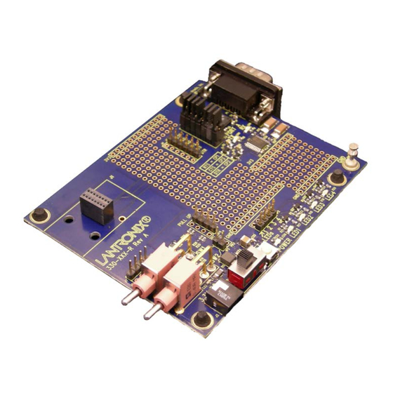
The Demo board included in the XPort Universal Demonstration Kit is a circuit board that the XPort, XPort Pro, or XPort Pro Dev board would be installed on. This board has a power supply connector, UUT socket, RS-232 transceiver, and DB9 serial connector. A power supply and necessary cables are included with the Demo Board in the XPort Universal Demo Kit. -
Page 5: Additional Documentation
1: Introduction Additional Documentation The following guides are available on the Lantronix website (www.lantronix.com). Hardware Related XPort Integration Guide Provides information for integrating the XPort module on a customer platform. XPort Pro Integration Provides information about the XPort Pro hardware, Guide and integrating the XPort Pro into your product. -
Page 6: Demonstration Kit
2. Demonstration Kit Using an XPort sample and the XPort Demonstration Kit, you can get familiar with the product and understand how to integrate the XPort into a given product design. Contents of the Kit The XPort Demonstration Kit contains the following items: ... -
Page 7: Demo Board Block Diagram
2: Demonstration Kit Demo Board Block Diagram The following drawing is a block diagram of the XPort Demo Board showing the relationships of the components. Figure 2-1. Demo Board Block Diagram Serial Interfaces The demo board has an RS-232 transceiver for connection to the XPort internal UART. -
Page 8: Power Supply
CP arrangement in the tables above is for demonstration purposes only. All CPs can be used as GPIOs. In XPort Pro custom applications, any CP can be assigned as any function except that only CP1 can be assigned to RTS in RS-232 mode or TX Enable in RS485 Mode, and only CP3 can be assigned to CTS in RS- 232 Mode. -
Page 9: Configuration For Modem Control
2: Demonstration Kit Configuration for Modem Control By default, on this demo board, the DCD and DSR signals are not routed to the XPort module. This makes it necessary to jumper the pins in JP6 in order to route the signals to the desired CPs on the XPort module. -
Page 10: Demo Board Schematics
2: Demonstration Kit Demo Board Schematics Figure 2-3. Demo Board Schematics XPort Universal Demo Board User Guide... -
Page 11: Figure 2-4. Rs-232 Transceiver
2: Demonstration Kit Figure 2-4. RS-232 Transceiver XPort Universal Demo Board User Guide... -
Page 12: A: Warranty
Warranty For details on the Lantronix warranty replacement policy, go to our web site at http://www.lantronix.com/support/warranty/index.html. XPort Universal Demo Board User Guide...
Need help?
Do you have a question about the XPORT and is the answer not in the manual?
Questions and answers