Table of Contents
Advertisement
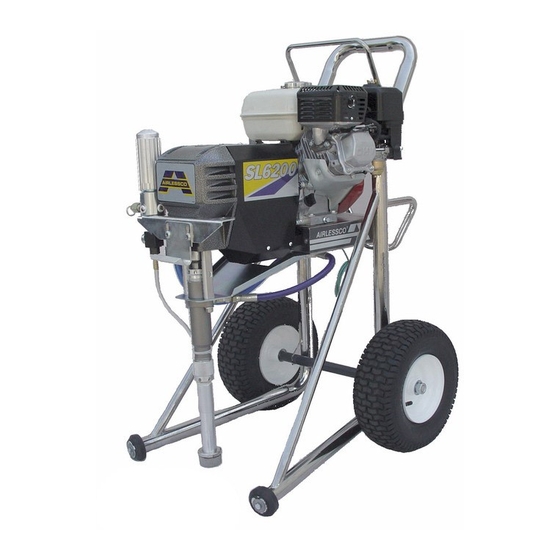
SL6200/1200G Gasoline Powered
SERVICE & OPERATION MANUAL
Specifi cations:
Usage:
For Spraying:
Features:
Performance:
BUILT TO PERFORM...
BUILT TO LAST
BUILT TO LAST
Airless Paint Sprayer
7,500 Gallons per Year
Large New Residential Projects,
Medium to Large Commercial Buildings, Industrial Use
Latex - High Solids
Oil Based Paint
Stain
Enamels
High Torque Clutch - 6 in. diameter
Stainless Steel "Slow Stroking" Paint Pump
High Pressure Filter
Triple Life Packings
Spray Tip Size
Pressure Flow
Free Flow
Engine 5.5 HP Honda - Overhead Cam - Oil Alert
Weight-LoBoy/HiBoy
Hose Length up to
Lacquers
Epoxy
100% Acrylics
Mastics
Elastomerics
Dry Fall/Fog
Block Fillers
1 Gun up to 0.041 in.
2 Guns up to 0.028 in.
1.5 GPM
5.7 Ltr/Min.
1.6 GPM
6.1 Ltr/Min.
134/144 Lbs 61/65 Kgs
300 Feet
91 Meters
001-553 JUL03
001-553 JUL03
001-553 JUL03
001-553 JUL03
Advertisement
Table of Contents
Troubleshooting

Related Manuals for AIRLESSCO SL6200


Summary of Contents for AIRLESSCO SL6200
- Page 1 SL6200/1200G Gasoline Powered Airless Paint Sprayer SERVICE & OPERATION MANUAL Specifi cations: Usage: 7,500 Gallons per Year Large New Residential Projects, Medium to Large Commercial Buildings, Industrial Use For Spraying: Latex - High Solids Lacquers Epoxy Oil Based Paint 100% Acrylics...
-
Page 2: Table Of Contents
Power Unit Assembly - Lo-Boy Frame Assembly -Lo-Boy Suction Assembly Accessories Manufactured by: AIRLESSCO BY DUROTECH CO. P.O.BOX 8006, MOORPARK, CA. 93020-8006 SHIP TO: 5397 COMMERCE AVE. MOORPARK, CA. 93021 TELEPHONE: 805-523-0211 FAX: 805-523-1063 Copyright 2003, All rights reserved. Subject to change without notice. -
Page 3: Introduction
4, 5, 6, & 7 and FOLLOW the Pressure Relief Pro ce dure on Page 6. All Service Procedures to be performed by an Authorized Airlessco Service Center ONLY. NO MODIFICATIONS or alterations of any AIRLESSCO Equipment or part is allowed. -
Page 4: How To Flush
HOW TO FLUSH FIG. 3 FIG. 1 REMOVE SPRAY Choke Lever FIG. 2 Closed Fuel Valve (Pressure) PRESSURE CONTROL Throttle Lever KNOB FIG. 4 High MAINTAIN FIRM PRIME VALVE & Pressure METAL TO METAL PRESSURE RELIEF CONTACT BETWEEN VALVE Pressure Open GUN AND CONTAINER (Priming &... -
Page 5: Setting Up
2. Fill the Packing Nut/Wet Cup bodily injury and property damage. Always Fill the Packing Nut/Wet Cup 1/3 full with Airlessco shut off the engine and let it cool before fill- Throat Seal Oil (TSO). Fig 5 below. -
Page 6: Starting Up
STARTING UP - continued 4. Prime the Pump 7. Cleaning a Clogged Tip a. Allow pump to operate until paint comes from gun. IMPORTANT WARNING b. Release the trigger and engage the gun safety latch. Always follow the Pressure Relief Procedure on page 8 c. - Page 7 WARNINGS HIGH PRESSURE SPRAY CAN CAUSE EXTREMELY SERIOUS INJURY. OBSERVE ALL WARNINGS. THIS SPRAYER IS FOR PROFESSIONAL USE ONLY. ALWAYS INSPECT SPRAYING AREA INJECTION HAZARD Fluids under high pressure from spray or leaks can Keep spraying area free from obstructions. penetrate the skin and cause extremely serious injury, Make sure area has good ventilation to safely remove vapors and mists.
-
Page 8: Pressure Relief Procedure
Step 5. If you suspect that pressure hasn't been relieved due to damaged prime/pressure relief valve or other reason, engage gun safety latch and take your sprayer to an authorized Airlessco Service Center for service. Always follow recommended pressure & operating... -
Page 9: Warnings 6,7,8
WARNINGS - Continued AVOID COMPONENT RUPTURE PREVENT STATIC SPARKED FIRE/ EXPLOSIONS This sprayer operates at 3000 psi (205 bar). Always ALWAYS be sure all equipment and objects being sprayed are properly grounded. Always ground sprayer, paint bucket be sure that all components and accessories have a and object being sprayed. -
Page 10: Spray Technique 10
SPRAY TECHNIQUE Good Spray Gun Technique is at the core of any spray If you are not familiar with spraying techniques, paint operation. Operator skill and efficiency is as we recommend that you study this section of important as good equipment and good paint. Good your manual and practice the proper technique spray technique is a skill that can be quickly learned by on pieces of cardboard or a suitable surface. - Page 11 SPRAY TECHNIQUE - Continued TOTAL SPRAYGUN MOVEMENT - arm movement - full sweep TRIGGER TRIGGER POINT POINT It is important to "trigger" the gun after gun movement (arm movement) has started and release trigger (shut gun off) before gun movement ends. Gun movement is always longer than actual paint (spray) stroke.
-
Page 12: Airless Spray Gun Operation
AIRLESS SPRAY GUN OPERATION DEFECTS CAUSE CORRECTION Coarse spray Low pressure Increase the pressure. Excessive fogging High pressure Reduce the pressure to satisfactory pattern distribution. (overspray) Material too thin Use less thinner. Pattern too wide Spray angle too large Use smaller spray angle tip. Pattern too narrow Spray angle too small Use larger spray angle tip (if coverage is OK, try tip... -
Page 13: Rev-Tip ™ Selection Chart
REV-TIP ™ SELECTION CHART Spray tip selection is based on paint viscosity, paint type, and Spray tip size is based on how many gallons of paint per minute can job needs. For light viscosities (thin paints), use a smaller tip; be sprayed through the tip. -
Page 14: Regular Maintenance
2. Keep the displacement pump packing nut/wet cup 1/3 full of If seepage of paint into the packing nut and/ Airlessco Throat Seal Oil at all times. The TSO helps protect the packings and rod. or movement of the piston upward is found (while not spraying), the packing nut should be 3. -
Page 15: Servicing Fluid Pump
PROBLEM CAUSE SOLUTION The engine and displace- The pressure setting is too low. Increase the pressure, see page 4, step 5. ment pump operates, but The tip or gun filter is clogged. Remove the tip and/or filter and clean them. paint pressure is too low or The tip is worn. -
Page 16: Servicing Inlet And Outlet Valves
SERVICING INLET & OUTLET VALVES INLET VALVE (See FIG. 9 & 11) FIG. 9 1. Using the rod collar tool (189-211), screw the suction nut (187-018), containing intake seat support (187-017), off of the fluid body (187-313). 2. Remove the inlet seat (187-065), O-ring (106-017), inlet PISTON ball (187-020) and ball cage (187-016) with O-ring (106-018). -
Page 17: V-Packing Replacement
V-PACKING REPLACEMENT V-PACKING REPLACEMENT KIT FIG. 10 SEVERE DUTY- PART NO. 187-040 Contains: Leather & Plastic Packings, PTFE & Viton O-Rings, Balls & plastic dual sided female adaptor & Larger Male Glands. GLAND KIT - Part Number 187-064 V-PACKING REPLACEMENT 187-026 INSTRUCTIONS (FIG. -
Page 18: V-Packing Replacement
V-PACKING REPLACEMENT (Continued) FIG. 11 187-046 106-018 106-014(OPT.) 187-315 187-047 187-016 106-013 187-020 187-037 187-065 106-012 187-026 106-017 187-313 187-029 187-059 187-330-99* 187-017 187-030 187-060 187-058 187-018 187-062* 187-025 187-029 187-059 106-021* 301-094 187-031 115-022 187-037 187-061 141-010 187-051* * INCLUDED WITH 187-330-99 PISTON ASSEMBLY REASSEMBLY 6. -
Page 19: Ball Valve
BALL VALVE - Part Number 100-119 FIG. 12 PARTS LIST - FIG.12 ITEM NO. PART NO. DESCRIPTION 100-162 Handle 100-163 Screw 100-164 Ball KIT-119 Repair Kit TROUBLESHOOTING - Clutch Does Not Engage STEP 1: Ensure that the pressure control knob (POT) is in the maximum (CW) position. STEP 2 : Remove the upper and lower clutch and electrical covers. -
Page 20: Replacement Of Electrical Control Board
REPLACEMENT OF ELECTRICAL CONTROL BOARD Hi Boy Fig 22 Item 37 1. Remove electrical cover. 5. Using a 1/2" nutdriver or 1/2" deep socket, remove Lo Boy Fig 23 Item 27 nut from pressure control shaft. This will allow removal of electrical control board from frame. -
Page 21: Clutch Replacement - Hi-Boy
CLUTCH REPLACEMENT - HI-BOY REMOVE CLUTCH AS FOLLOWS: (See Figs. 15 & 17) 5. Place gearbox in vice by gripping the flat portion of the drive crank allowing the clutch assembly to face up. Use caution and not allow gearbox to swing and damage 1. -
Page 22: Clutch Replacement - Lo-Boy
CLUTCH REPLACEMENT - LO-BOY REMOVE CLUTCH AS FOLLOWS: INSTALL NEW CLUTCH CONTINUED 1. Remove the upper and lower clutch covers (Fig. 23, 5. Lay removable spacer (Item 4) on top of last bearing. Item 27, 11). If the clutch air gap is larger than .028", do not use removable spacer. -
Page 23: Clutch Assembly Parts Lists
CLUTCH REPLACEMENT - LO-BOY FIG. 14 FIG 14 PARTS LIST ITEM NO. PART NO. DESCRIPTION 301-231 Cog Belt 301-264 Clutch Replacement 305-088 Screw 100-175 Shoulder Screw 100-173 Screw Flanged (4) 100-174 Set Screw (2) 301-534 Block Tensioner 301-208 New Gearbox 305-045 Plate 305-046... -
Page 24: Engine Assembly Parts Lists
ENGINE ASSEMBLY HI-BOY FIG. 17 GEARBOX ENGINE FIGURE 17 PARTS LIST ITEM PART DESCRIPTION ITEM PART DESCRIPTION 112-029 Key (3/16 x 1 1/2) 301-272 Insert (2) 100-357 Screw, Soc (1) 136-091 Screw, cap 5/16 - 24 (4) 301-222A Hub/Sheave Ass'y 10 100-383 Screw, soc 3/8 - 24 (4) 301-229... -
Page 25: Paint System Assembly Parts List- Hi-Boy
PAINT SYSTEM ASSEMBLY - HI-BOY Part Number 301-452 FIG. 19 Part # Description 100-028 1/4" Plug 100-070 1/4" x 1/4" Nipple 100-109 3/8" x 1/4" Nipple 100-119 Ball Valve 100-123 3/8" x 21" Hose 100-129 3/8" Plug 100-141 3/8"M x 1/4"M Elbow 100-161 3/8"... -
Page 26: Paint System Assembly Parts List- Lo-Boy
PAINT SYSTEM ASSEMBLY - LO-BOY FIG. 20 FIG. 20 PARTS LIST, PAINT SYSTEM ASSEMBLY ITEM NO. PART NO. DESCRIPTION ITEM NO. PART NO. DESCRIPTION 188-177 1/4" Return Tube 120-201XL 007 Gun w/Swivel (Optional) 169-013 3/8"M x 3/8"M Elbow (x2) 100-111 50' x 1/4"... -
Page 27: Manifold Filter
MANIFOLD FILTER - PN 111-200-99 FIG. 21 FIGURE 21 PARTS LIST ITEM PART NO. DESCRIPTION 111-202 Base* 301-356 Spring* 106-007 O-Ring* 111-204 Filter 111-203 Support* 111-201 Base* 169-013 3/8" M x 3/8" M Elbow 100-034 3/8" NPT (M) x 3/8" NPS (M) Hose Connector 100-129 Plug 3/8"... -
Page 28: Complete Sprayer Parts List - Hi-Boy 28
COMPLETE SPRAYER - HI BOY FIG. 22 25 26 27 See pg.22 Fig. 17 41,42, 43,44 See pg. 23 Fig 19 14, 14a 35 34... - Page 29 FIGURE 22 PARTS LIST ITEM PART DESCRIPTION ITEM PART DESCRIPTION 29 175-021 Air Filter , Engine 301-092 Shield - rear 30 301-239 Frame Weldment, Gas 301-189 Shield - front 301-105 Hook 31 301-149 Spacer 32 163-016 Spacer (2) 100-360 Screw (2) 33 301-165 Wheel (2) 100-312...
-
Page 30: Power Unit Assembly - Lo-Boy
POWER UNIT ASSEMBLY - LO-BOY FIG. 23 24 23 28 27 10 11 12 13 See Page 16 Fig. 11 See Page 30 Fig. 25 FIG. 23 PARTS LIST, POWER UNIT ASSEMBLY, PN 301-530 Item No. Part No. Description Item No. Part No. -
Page 31: Frame Assembly -Lo-Boy
FRAME ASSEMBLY - LO-BOY FIG. 24 FIG. 24 PARTS LIST, FRAME ASSLY, 301-515 ITEM # PART NO. DESCRIPTION 301-510 Frame Weldment 188-367 Axle 5/8 x 21.81" 113-031 Spacer 5/8" ID x 1" 301-165 Wheel (2) 13x500-6 143-029 Set Collar (2) 5/8" 100-317 Centerlock Nut (2) 5/16-18 163-008A... -
Page 32: Accessories
Filter Spring ADAPTERS 90° Pole to Gun Adapter 032-042 Gun Nut “F” Thread 11/16-16 032-010 For a complete listing of all available accessories see Gun Nut “G” Thread the Airlessco Accessories Catalog, Part # 001-357. 032-011 FORM NO. 001-553 JUL03...
Need help?
Do you have a question about the SL6200 and is the answer not in the manual?
Questions and answers